 Borhen Torchani1
 Ahmad Taher Azar2,3,4*
 Anis Sellami1Saim Ahmed2,3
 Ibrahim A. Hameed5*
 Ibraheem Kasim Ibraheem6Moamin Ibrahim Jameel Al-Obaidi7
- 1LISIER Laboratory, ENSIT, University of Tunis, Tunis, Tunisia
- 2College of Computer and Information Sciences, Prince Sultan University, Riyadh, Saudi Arabia
- 3Automated Systems and Soft Computing Lab (ASSCL), Prince Sultan University, Riyadh, Saudi Arabia
- 4Faculty of Computers and Artificial Intelligence, Benha University, Benha, Egypt
- 5Department of ICT and Natural Sciences, Norwegian University of Science and Technology, Alesund, Norway
- 6Department of Electrical Engineering, College of Engineering, University of Baghdad, Baghdad, Iraq
- 7Department of Communication Technical Engineering, Uruk University, Baghdad, Iraq
This article presents an innovative APISMC method applied to PVS, integrating the MPPT technique for a boost converter. The primary objective of this approach is to maximize the converter’s output power while ensuring optimal operation in the face of varying environmental conditions such as solar irradiance and temperature, while dynamically adapting to variations in system parameters, as demonstrated by the obtained results. To achieve this, a RVO is employed to generate reference voltage and power. A PI controller calculates the reference current based on this power. The APISMC control modeling utilizes all its reference variables to synthesize the sliding surface and duty cycle for optimal boost converter control. Simulations conducted demonstrate superior performance in terms of stability, speed, and control of the converter compared to traditional MPPT algorithms. The main contributions of this article include an improvement in system robustness against irradiance variations, thanks to the integration of an adaptive algorithm and a PI controller within the SMC. Moreover, the proposed theoretical and practical framework enables rapid MPPT attainment by adjusting the duty cycle in real-time, optimizing maximum power extraction and ensuring stable regulation even under non-ideal conditions.
1 Introduction
Renewable energies are alternative energy sources to fossil fuels, which are limited and polluting. They are essential for the energy transition towards a more sustainable world. Among renewable energies, PV solar energy is one of the most promising. It is clean, inexhaustible, and available in most countries around the world. It is rapidly developing and becoming increasingly efficient and affordable. However, the most important challenge is to find technical means to maximize the energy production of PVS, particularly through better control of converters. Thus, their performance heavily depends on the control techniques applied. One of the techniques often used and commercialized is MPPT. Indeed, it is an algorithm that allows for finding the MPP of a PV system. In other words, it can be characterized as the point where the output power generated by the converter system is maximized for a given output voltage. Several studies have focused on the control of PVS using the MPPT technique (Poongavanam et al., 2023; Velmurugan et al., 2022; Vankadara et al., 2022; Vankadara et al., 2023). Various types of classic MPPT algorithms have been developed for PVS, such as the Incremental Conductance (INC) algorithm, which offers good responsiveness to rapid changes but may suffer from increased complexity and sensitivity to measurement errors (Atia et al., 2022; Chellakhi et al., 2024; El Ouardi et al., 2023; Ahmed et al., 2022). The RVO control is another approach that adjusts the reference voltage to maximize power but may be limited by non-ideal operating conditions (El Fadili et al., 2014). Also noteworthy is the PO control, which is simple to implement and effective under steady-state operating conditions (Ali and Mohamed, 2022; Gomathi et al., 2024; Kumar and Bindal, 2022). However, it may perform less well under rapid variations in irradiation, leading to oscillations around the MPP, among other commonly used techniques. These techniques are straightforward to implement and provide good performance. Nevertheless, they can be sensitive to variations in temperature and illumination. Currently, new control techniques for PVS and converters are being developed, including those utilizing artificial intelligence (Remoaldo and Jesus, 2021; Mazumdar et al., 2024; Aljafari et al., 2023; Radhakrishnan et al., 2022; Oliver et al., 2022), such as neural networks control algorithm (Cano et al., 2024; Maguluri et al., 2023; Oh et al., 2024; Sahoo et al., 2022; Saxena et al., 2021), fuzzy logic control (Abdelmalek et al., 2018; Chandrashekar et al., 2024; Derbeli et al., 2023; Hussain et al., 2024), and adaptive controls (Henao-Bravo et al., 2022; Li et al., 2024; Stitou et al., 2022; Ouaret et al., 2023).
PVS are subjected to sudden external variations, such as changes in temperature and irradiation. However, traditional controllers are often ineffective and lack robustness against these external disturbances. Therefore, converters generally require high-performance and robust controls in terms of speed and accuracy to meet the load requirements under variable conditions and to maintain performance even in the presence of uncertainties and disturbances. In reality, PV systems, where the converter is a key element, require good regulation of their duty cycle (Corrêa and Vieira, 2023; Youssef et al., 2023). Maintaining precise duty cycle control is essential for optimizing the voltage and power at the output of the converter. For this reason, robust, adaptive, and fuzzy controls are more complex but offer better robustness against environmental variations. For this work, Sliding Mode Control (SMC) is recognized for its robustness and ability to manage nonlinear systems, making it a preferred choice for PVS (Chaibi et al., 2019; Muktiadji et al., 2022; Singh et al., 2017; Swarnkar et al., 2022). By its nature, this control is a nonlinear control algorithm that allows for managing the dynamic systems of the PV and the converter in the presence of disturbances and uncertainties (Azar and Serrano, 2015; Chang et al., 2024; Gundecha et al., 2016; Tian et al., 2019; Samadhiya et al., 2021; Samadhiya and Namrata, 2021; Vaidyanathan and Azar, 2016). It is based on constructing a sliding surface, which represents the operating space of these two systems. The SMC maintains the dynamical system on the sliding manifold modeled by the system’s current and voltage relative to the reference currents and voltages. This ensures its correct operation and rapid response. The choice of parameters for the sliding surface is a crucial point for optimizing the control operation from a dynamic and rapid perspective. Thus, the combination of SMC control and adaptive parameter control leads to a certain optimization that enhances the performance of conventional SMC control to very significant results. Several studies have addressed the integration of SMC control with adaptive control (Alnami et al., 2024; Rahme et al., 2023), neural networks (Ruz-Hernandez et al., 2024; Wang et al., 2023), PI controllers (Bhat et al., 2020; Chinnappan et al., 2019), and fuzzy logic (Ezhilan et al., 2022; Said Adouairi et al., 2023).
In the literature cited in previous paragraphs, many existing MPPT techniques, such as Incremental Conductance and Perturbation and Observation, exhibit sensitivity to environmental variations, leading to degraded performance during rapid changes in irradiation or temperature, resulting in oscillations around the maximum power point. Additionally, traditional controllers often lack robustness against external disturbances, making it difficult to accurately regulate the output voltage and converter performance. Another noteworthy point is the complexity of algorithms. Indeed, several recent approaches, particularly those using artificial intelligence, while effective, can be too complex for practical and robust implementation in real-time systems. The APISMC proposed in this article aims to address these shortcomings by integrating an adaptive control that allows for dynamic adjustment of control parameters based on environmental variations, thus improving system stability and response speed. Additionally, APISMC control relies on robustness, combining SMC control with adaptive algorithms, the approach ensures accurate regulation of the output voltage, even in the presence of uncertainties and disturbances.
The article presents an innovative APISMC control method applied to PVS, integrating the MPPT technique for the boost converter. This approach aims to maximize the converter’s output power while ensuring optimal operation, even in the face of environmental variations such as solar irradiance and temperature. Consequently, a new MPPT approach is designed, using APISMC control for the PVS and the boost converter, aimed at improving robustness against environmental variations and subsequently maximizing the extracted power. Furthermore, the improvement of robustness against irradiation variations is achieved by integrating the PI controller and the adaptive algorithm into the SMC control. Simulation results show that the APISMC MPPT algorithm offers superior performance compared to conventional MPPT algorithms under SMC or PO control. It is capable of quickly tracking changes in irradiation and maintaining maximum output power by monitoring it against the reference. However, it should not be overlooked that traditional MPPT controllers, which are simple to implement and provide good performance under nominal conditions, can be sensitive to variations in temperature and irradiation.
The organization of this article is as follows: In Section 2, we will present the PV model by outlining the main mathematical equations relating the photo-generated current to solar irradiation and temperature, the total current, and finally the power provided by the panel. Afterwards, the modeling of the boost converter will be established in Section 3. The converter is presented through the relationships that connect the input and output voltages of the converter and the current through the coil, which is often confused with the output current. This modeling includes the integration of the duty cycle between the input and output electrical variables, leading to the development of the output power of the converter. The importance of the RVO technique and its operating algorithm are discussed in Section 4. In Section 5, we emphasize the objectives of the APISMC control and the benefits of integrating the adaptive algorithm and PI control into the SMC. The development of the suggested APISMC will be discussed in Section 6, involving the designing of the sliding surface and the various components of the proposed control system, and also the confirmation of the system’s stability through the use of the APISMC. In Section 7, the application of the proposed control will be implemented through numerical simulations of the photovoltaic system and the boost converter. The effectiveness of the proposed control is verified against other control techniques. Finally, in Section 8, we will present a conclusion highlighting the main results obtained and potential perspectives to conclude this work.
2 Modeling of the photovoltaic system
In this section, we propose the modeling of a cell in a PVS. The various mathematical equations materializing this electrical diagram of the photovoltaic cell will be given below.
2.1 Equation of the PV module current
The equation for the current of the PV module is given as follows:
The different variables and parameters of Equation 1 are given in nomenclatures section at the beginning.
2.2 Equation for the total current of the PV system
To obtain this equation, we divide the current of the PV module
2.3 Equation of the photo-generated current
The photo-generated current depends on the illumination and the temperature:
where the different parameters of Equation 3 are defined in nomenclatures section at the beginning.
2.4 Power equation of the PVS
The electrical power generated by the PV panel is the product of the current given by Equation 2 and the voltage, and it is expressed as follows:
the parameters of Equation 4 are given by:
3 The boost converter
To adapt the output voltage of the photovoltaic system to the load, we plan to choose a boost-type voltage converter. The focus will be on the equations relating the input and output voltage of the converter to the current flowing through the inductor circuit. In reality, the inductor current
3.1 Presentation of the boost converter
The boost converter is governed by the two known operating modes called ‘ON’ and ‘OFF’. The input voltage-output voltage relationship can be described as follows:
with
The input voltage
and
Using Equations 4–7, we can reformulate this converter problem based on the dynamics control relying on the voltage
3.2 Duty cycle of the boost converter
The integration of
For a boost converter, the duty cycle
Equation 8 shows that the duty cycle is proportional to the output voltage relative to the sum of the input and output voltages. A higher duty cycle means that the converter is active for a longer duration, which allows for an increase in the output voltage.
Subsequently, the boost converter’s output voltage is given by:
By analogy to Equation 9, the output current is expressed by the following relationship:
From Equations 9, 10 it is clear that the choice of the duty cycle
3.3 Output power of the boost converter
To find an expression for the output power
with
Since
with
Equations 13, 14 highlights the importance of choosing
4 The RVO technique
The integration of the RVO algorithm into the calculation of the duty cycle
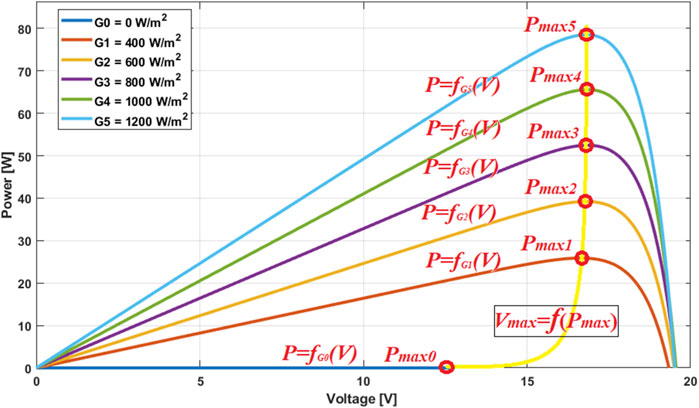
Figure 1. Power-voltage characteristic: Extraction of maximum power points.
To make this technique more effective, the goal will be to maintain
In Equation 15,
Algorithm 1.Adaptive RVO algorithm
BEGIN
// Initialize parameters
INITIALIZE Vref, k0, Pin, Pout
SET alpha// Learning rate for gradient descent
// Main loop
WHILE (termination condition not met) DO
// Measure Vin
MEASURE Vin
// Calculate Vref
Vref = k * Vin
// Calculate D
D = Vout/ (Vout + Vin)
// Evaluate output power
Pout_new = D * Pin
// Optimize k
k_gradient = CALCULATE_gradient(Pout_new, k)
// Calculate the derivative of Pout with respect to k
k = k + alpha * k_gradient// Adjust k
// Evaluate performance
IF (Pout_new > Pout) THEN
Pout = Pout_new// Keep the new Pout value
ELSE
k = k - alpha * k_gradient// Adjust k in the opposite direction
END IF
END WHILE
END
5 Objectives of APISMC control
It should be noted that if the duty cycle is too large, i.e., very close to the value
The adaptive SMC aims to maintain the performance of the boost converter in the face of unexpected variations in system parameters, such as load changes or input voltage
The APISMC allows quick and effective reaching of the MPPT by adjusting the duty cycle in real-time, according to changes in irradiance
Since variations in
In summary, the objectives of the APISMC technique are as follows:
• Balance power and efficiency: Avoid overheating losses while ensuring the desired output voltage is achieved.
• Adapt to unexpected variations: Maintain performance in the face of changes in system parameters such as load variations or input voltage fluctuations.
• Improve dynamic stability: Ensure a rapid system response to state changes and maintain the output voltage at the desired reference value without undesirable oscillations.
• Rapidly achieve MPP: Adjust the duty cycle in real-time based on variations in irradiance and temperature to quickly reach the maximum power point.
• Ensure disturbance insensitivity: Maintain the performance of the boost converter even in the presence of disturbances and variations in input voltage or load.
6 Synthesis of the APISMC control
The design of the sliding surface ensures that the system remains stable during operation. By defining a specific trajectory for the system’s state variables, it helps maintain the desired performance even under varying conditions. Additionally, it allows the control system to be robust against external disturbances such as changes in solar irradiance or temperature. This robustness is crucial for maintaining optimal performance in real-world scenarios.
The sliding surface
with and are weighting coefficients. The parameters
The sliding surface consists of the error between the desired and actual values of the voltage
To introduce the PI part into the control, we modify the definition of
where
The parameters
The sliding surface is designed by integrating the PI part into the surface given by Equations 16-17, we then obtain:
or alternatively
then
To satisfy Equations 18–20 and to make the system adaptive, the gains
where
where
By using Equations 16, 21 we combine the two parts, the adaptive expression for
The control gain
The calculation of the derivative of the cost function with respect to
and the update of
Using Equations 22–25, the expression for the control of the APISMC control system can be formulated by combining the contributions from the PI part and the SMC part, as follows:
The continuous component of the control is given by the PI control, as follows:
The discontinuous component is given by:
Thus, the final expression of the adaptive APISMC control to generate the duty cycle
The switch activation duration
where
Overall, this activation duration can be expressed in terms of the control as follows:
All the analytical relationships presented earlier for developing the sliding surface, the APISMC control given by Equations 26–29, and the switch activation duration given by Equations 30–32 are illustrated by the explanatory diagram in Figure 2. It is a diagram linking the different components of the PVS and the boost converter with the adaptive APISMC control, which is provided below.
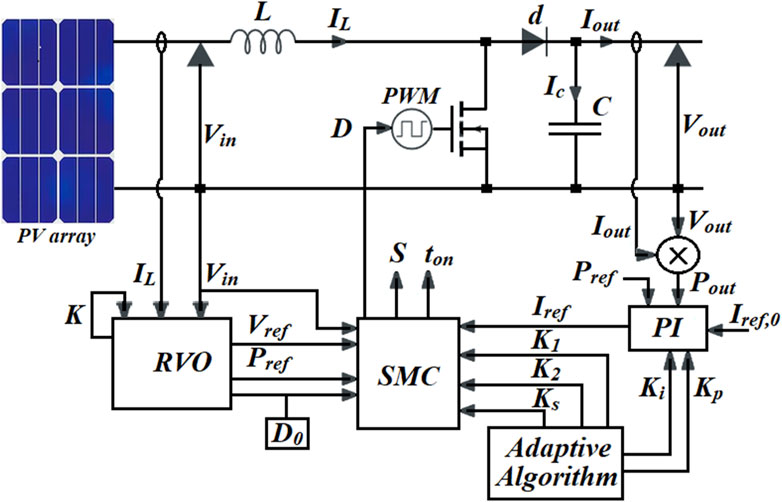
Figure 2. Diagram of the different components of the PVS system with the APISMC.
To demonstrate the stability of the system using the candidate Lyapunov function, we will start from the inequalities and make simplifications through approximation. We will establish the conditions on the parameters that ensure the derivative of the Lyapunov function is negative.
We define the candidate Lyapunov function as follows:
where the sliding surface
Calculating the derivative of the surface S:
For the system to be stable, we must have:
using Equations 33–36, this implies that:
Considering the condition of Equation 37, we assume that the errors
Using absolute values, we can write:
Therefore, to ensure that
We generally consider that the derivatives
For
Considering Equations 37–41, in summary, if the gains
7 Numerical simulation
In this section, we will present the simulations conducted to validate the proposed control synthesis, namely, the APISMC control in the Matlab environment. These simulations aim to demonstrate the effectiveness and robustness of the APISMC in the context of MPPT for a photovoltaic system. By comparing the results obtained with those from conventional control methods, we will be able to evaluate the performance of the APISMC control in terms of stability, response speed, and ability to adapt to variations in environmental conditions.
We use a PV array containing 54 cells that are connected in series. The PV system delivers its power in parallel to the DC/DC boost converter. The parameters, including information on the electrical characteristics of the photovoltaic system under varying irradiation conditions, are provided below in Table 1.
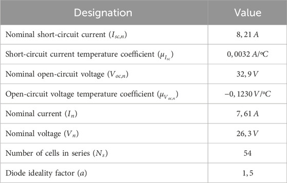
Table 1. The values of the photovoltaic system parameters.
The parameters, including information on the electrical characteristics of the boost converter under varying irradiation conditions, are provided below in Table 2.
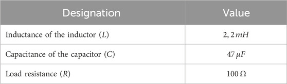
Table 2. The values of the boost converter parameters.
The adaptive algorithms allow to obtain each time the values of the gains (
For the case of the conventional SMC control, the parameters are manually adjusted to obtain the best responses, these parameters are given by:
Les valeurs du courant de référence et de duty cycle initiales sont données par:
and
The simulations conducted have generated various figures illustrating the performance of the proposed APISMC control for the photovoltaic system and the boost converter. Figure 3 presents the solar irradiation profile used as input to the system, reflecting the variations in solar irradiation over time. Figures 4, 5 show the current and voltage control signals generated by the APISMC, respectively, highlighting its ability to dynamically adapt to changes in environmental conditions. Figure 6 compares the sliding surfaces obtained with the APISMC and the conventional SMC control, demonstrating the improvement brought by the integration of adaptive algorithms and the PI controller. Figures 7–9 present the responses of current, voltage, and power under the proposed APISMC control, comparing them to the performance of conventional SMC and PO techniques. Figure 10 illustrates the variation of the duty cycle
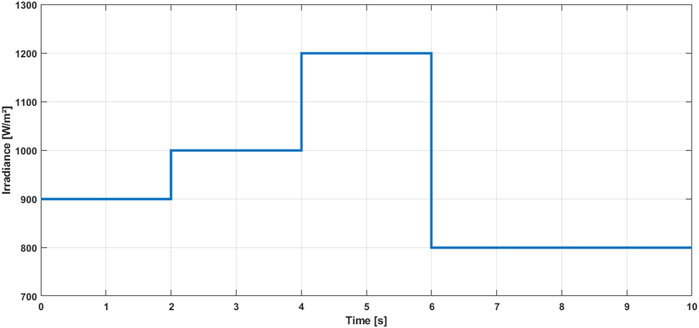
Figure 3. Sunlight profile defined by the received irradiation.
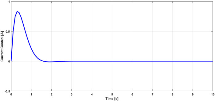
Figure 4. Current control signal generated by proposed scheme.
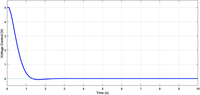
Figure 5. Voltage control signal generated by proposed scheme.
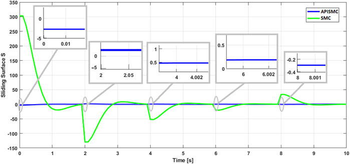
Figure 6. Sliding surface in both cases: conventional SMC and proposed PISMC.
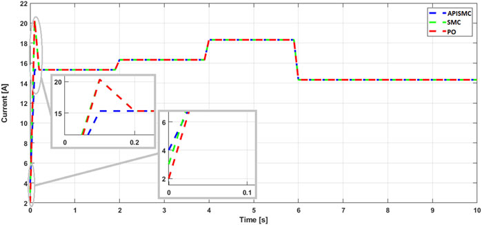
Figure 7. Current response by proposed APISMC and compared to SMC and PO.
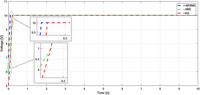
Figure 8. Voltage response by proposed APISMC and compared to SMC and PO.
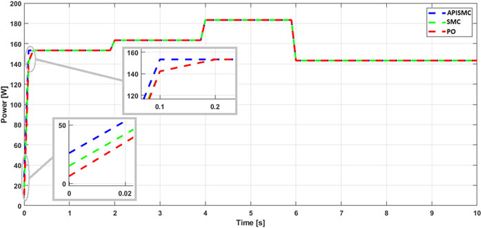
Figure 9. Power response by proposed APISMC and compared to SMC and PO.
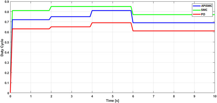
Figure 10. Duty cycle by proposed APISMC and compared to SMC and PO.
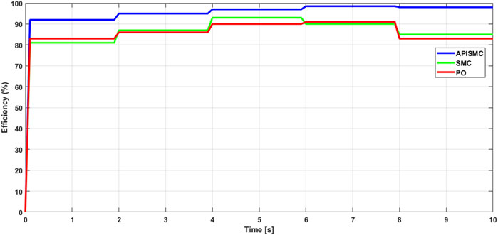
Figure 11. Efficiency of the different controls with temperature variation.
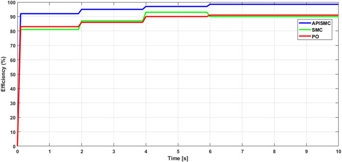
Figure 12. Efficiency of the different controls with irradiance variation.
Figure 3 shows the variation of the solar irradiation received over time. The irradiation follows a distribution characterized by the successive values of
There are minor fluctuations at the start of the signals shown in Figures 4, 5, but they quickly fade away after
Figure 6 presents the curve of the sliding surface
Overall, Figure 6 clearly demonstrates the effectiveness of the proposed control compared to SMC in mitigating the discrepancies between the system’s behavior and the optimal reference values. This highlights the effectiveness of the adaptive part of the control in optimizing the calculated values of
The simulations in Figures 7–9 present the variations of current, voltage, and typical power. Stability is achieved, with different convergence characteristics among the controls. The simulations of current, voltage, and power show that the proposed control exhibits a minimal response time of
These results highlight the effectiveness of the APISMC control in regulating the performance of the photovoltaic system. The rapid response of the control allows for effective adaptation to variations in sunlight conditions, thus ensuring optimal power extraction. In comparison, other control methods show longer settling times, which can affect their ability to react quickly to fluctuations in irradiation. Additionally, the APISMC control does not exhibit overshoot, unlike other controls that may reach an overshoot of
The validity of the APISMC compared to other control methods, namely, SMC and PO, is clearly demonstrated in the management of the duty cycle
The simulations presented above in Figures 11, 12 were conducted by varying environmental conditions, specifically temperature and irradiance, to evaluate the performance of different MPPT control strategies. The results demonstrate that the APISMC consistently outperforms both SMC and PO in terms of efficiency. This superiority can be attributed to the adaptive and flexible nature of the APISMC parameters, allowing it to adjust in real-time to environmental variations. Consequently, APISMC is capable of maintaining an optimal operating point for the boost converter, regardless of temperature or irradiance, resulting in higher energy yields.
Simulations conducted with temperatures ranging from 15°C to 45°C and irradiance levels between 800 W/m2 and 1200 W/m2 revealed that APISMC achieved an average of 5% higher efficiency compared to SMC and PO. This improvement is due to APISMC’s ability to continuously adjust its parameters based on rapid irradiance fluctuations, enabling it to more accurately track the maximum power point. Additionally, APISMC’s robustness to disturbances, such as load variations, contributes to maintaining high efficiency under real-world conditions.
8 Results and discussion
The study has conclusively demonstrated the superiority of the APISMC controller over conventional SMC and PO control methods in the context of PV systems. Based on the simulations from the previous section, APISMC has excelled in several areas:
• Stability and responsiveness: The control signals generated by APISMC are remarkably smooth, indicating high system stability. Additionally, APISMC’s response time is significantly faster, enabling it to react quickly to variations in environmental conditions.
• Power optimization: By dynamically adjusting the duty cycle of the boost converter, APISMC effectively maximizes the output power of the PV system. This capability is essential for making the most of available solar energy.
• Adaptability: Thanks to its adaptive nature, APISMC can quickly adapt to changes in solar irradiance, which is particularly important in environments with variable weather conditions.
• Robustness: APISMC has demonstrated high robustness to disturbances, maintaining stable control even under challenging conditions. These superior performances can be attributed to the integration of adaptive algorithms and a PI controller within APISMC. These elements enable the controller to adapt in real-time to system variations and continuously optimize its performance. In comparison, conventional SMC and PO methods struggle to adapt quickly to environmental changes and may exhibit oscillations or slower response times. The efficiency results obtained in the simulations confirm these observations, showing that APISMC consistently outperforms other control methods. The use of APISMC in PV systems can lead to a significant increase in energy efficiency and better utilization of solar energy. Furthermore, the robustness and adaptability of APISMC make it a promising solution for applications in diverse and demanding environments. Overall, the proposed control exhibits a minimal response time, allowing for rapid adjustment of the duty cycle in response to variations in irradiance. This not only guarantees maximum power extraction but also ensures better system stability. In comparison, other control methods, while effective in certain conditions, exhibit longer stabilization times and reduced responsiveness, which can lead to performance losses in dynamic environments. Thus, APISMC proves to be a superior approach for duty cycle control, ensuring optimal converter management and maximizing PV system efficiency.
However, the APISMC control method has several limitations. First, its design and implementation can be quite complex, given the number of parameters used, especially with adaptive dynamics. Furthermore, the control gains must also be carefully tuned to ensure optimal performance, leading to a tuning process that can be time-consuming. Additionally, the computational cost associated with the calculations necessary for real-time adaptation can pose challenges in applications where processing resources are limited. These limitations emphasize the importance of thorough evaluation and testing in real conditions to ensure the method’s effectiveness in practical applications.
9 Conclusion
This article presents an in-depth study on the application of Proportional-Integral Sliding Mode Adaptive Control (APISMC) aimed at maximizing the output power of a photovoltaic system (PVS) through a boost converter. The main results of the simulations demonstrate the effectiveness of the proposed APISMC method compared to conventional Maximum Power Point Tracking (MPPT) techniques. The APISMC method significantly outperforms traditional MPPT algorithms such as Sliding Mode Control (SMC) and Perturb and Observe (PO) control, particularly under rapidly changing environmental conditions, proving its performance. In terms of robustness against variations, the integration of a Reference Voltage Optimizer (RVO) enables the APISMC to dynamically adapt to fluctuations in solar irradiation and temperature, thereby ensuring optimal power extraction in variable conditions. The simulations confirm that the proposed control method maintains system stability and responds quickly to changes in irradiation, effectively tracking the maximum output power while minimizing oscillations. The combination of adaptive control strategies with SMC leads to improved robustness and performance, making APISMC an optimal approach.
Overall, the results indicate that the APISMC method not only enhances the efficiency of photovoltaic systems but also provides a reliable solution for maximizing energy production in the face of environmental uncertainties. However, it is important to note certain drawbacks associated with the APISMC method. Notably, the complexity of implementing APISMC requires intricate modeling and precise parameter calibration, which can make its implementation more challenging compared to simpler methods. Another weakness is that the adaptive algorithm may demand greater computational resources, which may not be feasible in low-cost or low-power systems. To address this, several perspectives can be considered to improve the reliability and practical application of this control method. For this purpose, it would be interesting to integrate the proposed control with artificial intelligence techniques, as the use of machine learning and neural networks could further enhance the adaptability of the control.
Data availability statement
The original contributions presented in the study are included in the article/supplementary material, further inquiries can be directed to the corresponding authors.
Author contributions
BT: Conceptualization, Formal Analysis, Methodology, Validation, Visualization, Writing–original draft, Writing–review and editing. AA: Conceptualization, Formal Analysis, Investigation, Methodology, Supervision, Writing–original draft, Writing–review and editing. AS: Conceptualization, Formal Analysis, Methodology, Resources, Visualization, Writing–original draft, Writing–review and editing. SA: Formal Analysis, Investigation, Methodology, Resources, Validation, Writing–original draft, Writing–review and editing. IH: Data curation, Formal Analysis, Investigation, Methodology, Resources, Writing–review and editing, Funding acquisition. IK: Data curation, Formal Analysis, Resources, Validation, Writing–review and editing, Investigation, MA: Data curation, Formal Analysis, Resources, Software, Validation, Writing–review and editing.
Funding
The author(s) declare that financial support was received for the research, authorship, and/or publication of this article. This research was funded by Norwegian University of Science and Technology, Norway. This research was also supported by the Automated Systems and Soft Computing Lab (ASSCL), Prince Sultan University, Riyadh, Saudi Arabia.
Acknowledgments
The authors would like to thank the Norwegian University of Science and Technology, Norway for paying the Article Processing Charges (APC) for this publication. The authors specially acknowledge the Automated Systems and Soft Computing Lab (ASSCL) at Prince Sultan University, Riyadh, Saudi Arabia. In addition, the authors wish to acknowledge the editor and reviewers for their insightful comments, which have improved the quality of this publication. The authors would like to thank Prince Sultan University, Riyadh, Saudi Arabia, for support with the article processing charges.
Conflict of interest
The authors declare that the research was conducted in the absence of any commercial or financial relationships that could be construed as a potential conflict of interest.
Publisher’s note
All claims expressed in this article are solely those of the authors and do not necessarily represent those of their affiliated organizations, or those of the publisher, the editors and the reviewers. Any product that may be evaluated in this article, or claim that may be made by its manufacturer, is not guaranteed or endorsed by the publisher.
Abbreviations
PV, Photovoltaic; APISMC, Adaptive Proportional Integral Sliding Mode Control; PVS, Photovoltaic Systems; MPPT, Maximum Power Point Tracking; RVO, Reference Voltage Optimizer; SMC, Sliding Mode Control; PI, Proportional Integral; MPP, Maximum Power Point; PO, Perturbation and Observation.
References
Abdelmalek, S., Azar, A. T., and Dib, D. (2018). A novel actuator fault-tolerant control strategy of DFIG-based wind turbines using Takagi-Sugeno Multiple models. Int. J. Control, Autom. Syst. 16 (3), 1415–1424. doi:10.1007/s12555-017-0320-y
Ahmed, E. M., Norouzi, H., Alkhalaf, S., Ali, Z. M., Dadfar, S., and Furukawa, N. (2022). Enhancement of MPPT controller in PV-BES system using incremental conductance along with hybrid crow-pattern search approach based ANFIS under different environmental conditions. Sustain. energy Technol. assessments 50, 101812. doi:10.1016/j.seta.2021.101812
Ali, A. I. M., and Mohamed, H. R. A. (2022). Improved P&O MPPT algorithm with efficient open-circuit voltage estimation for two-stage grid-integrated PV system under realistic solar radiation. Int. J. Electr. Power & Energy Syst. 137, 107805. doi:10.1016/j.ijepes.2021.107805
Aljafari, B., Balachandran, P. K., Samithas, D., and Thanikanti, S. B. (2023). Solar photovoltaic converter controller using opposition-based reinforcement learning with butterfly optimization algorithm under partial shading conditions. Environ. Sci. Pollut. Res. 30 (28), 72617–72640. doi:10.1007/s11356-023-27261-1
Alnami, H., Hakmi, S. H., Abdelwahab, S. A. M., Abdellatif, W. S., Hegazy, H. Y., Mohamed, W. I., et al. (2024). Enhanced adaptive dynamic surface sliding mode control for optimal performance of grid-connected photovoltaic systems. Sustainability 16 (13), 5590. doi:10.3390/su16135590
Atia, M., Bouarroudj, N., Ahriche, A., Djari, A., and Houam, Y. (2022). Maximum power harvesting from a PV system using an improved two-stage MPPT scheme based on incremental conductance algorithm and integral controller. Int. J. Model. Identif. Control 40 (2), 176–191. doi:10.1504/IJMIC.2022.124722
Azar, A. T., and Serrano, F. E. (2015). “Stabilization and control of mechanical systems with backlash,” in Handbook of research on advanced intelligent control engineering and automation, advances in computational intelligence and robotics (ACIR) book series, USA (USA: IGI Global), 1–60.
Bhat, S., Nagaraja, H. N., and Thakur, P. (2020). DSP based proportional integral sliding mode controller with fast exponential reaching law for photo-voltaic system. Int. J. Adv. Res. Eng. Technol. (IJARET) 11 (5), 597–605. doi:10.34218/IJARET.11.5.2020.062
Cano, A., Arévalo, P., and Jurado, F. (2024). Neural network predictive control in renewable systems (HKT-PV) for delivered power smoothing. J. Energy Storage 87, 111332. doi:10.1016/j.est.2024.111332
Chaibi, Y., Salhi, M., and El-Jouni, A. (2019). Sliding mode controllers for standalone PV systems: modeling and approach of control. Int. J. Photoenergy 2019 (1), 1–12. doi:10.1155/2019/5092078
Chandrashekar, B., Pradeep, J., Sivasubramanian, M., Khandan, K. L., and Dhanraj, J. A. (2024) “A fuzzy logic controller for a photovoltaic system relying on a closed-loop DC-DC converter,” in Ninth international conference on science Technology engineering and mathematics (ICONSTEM), Chennai, India, 04–05 April, 2024. doi:10.1109/ICONSTEM60960.2024.10568741
Chang, Y., Yu, W., Luo, M., Zhou, F., Huang, W., and Zhai, G. (2024). Anti-interference control method of buck–boost converter based on high-order nonlinear disturbance observer. Electronics 13 (7), 1318. doi:10.3390/electronics13071318
Chellakhi, A., El Beid, S., Abouelmahjoub, Y., and Doubabi, H. (2024). An enhanced incremental conductance MPPT approach for PV power optimization: a simulation and experimental study. Arabian J. Sci. Eng. 49, 16045–16064. doi:10.1007/s13369-024-08804-1
Chinnappan, R., Logamani, P., and Ramasubbu, R. (2019). Fixed frequency integral sliding-mode current-controlled MPPT boost converter for two-stage PV generation system. IET Circuits, Devices & Syst. 13 (6), 793–805. doi:10.1049/iet-cds.2018.5221
Corrêa, H. P., and Vieira, F. H. T. (2023). Hybrid sensor-aided direct duty cycle control approach for maximum power point tracking in two-stage photovoltaic systems. Int. J. Electr. Power & Energy Syst. 145, 108690. doi:10.1016/j.ijepes.2022.108690
Derbeli, M., Napole, C., and Barambones, O. (2023). A fuzzy logic control for maximum power point tracking algorithm validated in a commercial PV system. Energies 16 (2), 748. doi:10.3390/en16020748
El Fadili, A., Giri, F., and El Magri, A. (2014). Reference voltage optimizer for maximum power point tracking in triphase grid-connected photovoltaic systems. Int. J. Electr. Power & Energy Syst. 60, 293–301. doi:10.1016/j.ijepes.2014.03.029
El Ouardi, H., El Gadari, A., Mokhlis, M., Ounejjar, Y., Bejjit, L., and Al-Haddad, K. (2023). A Novel MPPT technique based on combination between the incremental conductance and hysteresis control applied in a standalone PV system. Eng 4 (1), 964–976. doi:10.3390/eng4010057
Ezhilan, T., Govindharaj, A., Ambikapathy, A., Prajapati, B. M., Kumar, M., Singh, A. V., et al. (2022). “Adaptive sliding mode fuzzy logic controller for PV battery system,” in 2022 2nd international conference on advance computing and innovative technologies in engineering (ICACITE), Greater Noida, India, 28–29 April, 2022. doi:10.1109/ICACITE53722.2022.9823722
Gomathi, S., Mayurappriyan, P. S., and BabyPriya, B. (2024). Performance improvement of grid-tied PV system with boost and quadratic boost converters using innovatory hybridized HPO-PO MPPT. Electr. Power Components Syst., 1–13. doi:10.1080/15325008.2024.2318399
Gundecha, A. D., Gohokar, V. V., Mahapatro, K. A., and Suryawanshi, P. V. (2016). “Control of DC–DC converter in presence of uncertain dynamics,”. Intelligent systems technologies and applications. Advances in intelligent systems and computing. Editors S. Berretti, S. Thampi, and P. Srivastava (Cham: Springer), 384, 315–326. doi:10.1007/978-3-319-23036-8_27
Henao-Bravo, E. E., Ramos-Paja, C. A., and Saavedra-Montes, A. J. (2022). Adaptive control of photovoltaic systems based on dual active bridge converters. Computation 10 (6), 89. doi:10.3390/computation10060089
Hussain, K., Kaliappan, S., Saini, P., Kumar, S. N., and Dhanraj, J. A. (2024). “PV generation monitoring using calculated power flow from μPMUS,” in 2024 international conference on optimization computing and wireless communication (ICOCWC), Debre Tabor, Ethiopia, 29–30 January, 2024. doi:10.1109/ICOCWC60930.2024.10470487
Kumar, V., and Bindal, R. K. (2022). MPPT technique used with perturb and observe to enhance the efficiency of a photovoltaic system. Mater. Today Proc. 69, A6–A11. doi:10.1016/j.matpr.2023.01.002
Li, N. Z., Jiang, Y. X., and Wei, X. J. (2024). Model-free adaptive chaos control for the boost converter. Meas. Control 57 (5), 519–529. doi:10.1177/00202940231194117
Maguluri, L. P., Farook, S., Saravanan, R., Dixit, A., Aishwarya, K. P., and Dhanraj, J. (2023). “An appraisal in to the effects of partial shading on an urban photovoltaic system using the internet of things,” in 2023 international conference on advances in computing, communication and applied informatics (ACCAI), doi:10.1109/ACCAI58221.2023.10201066
Mazumdar, D., Sain, C., Biswas, P. K., Sanjeevikumar, P., and Khan, B. (2024). Overview of solar photovoltaic MPPT methods: a state of the art on conventional and artificial intelligence control techniques. Int. Trans. Electr. Energy Syst. 2024 (1), 1–24. doi:10.1155/2024/8363342
Muktiadji, R. F., Ramli, M. A., Bouchekara, H. R., Milyani, A. H., Rawa, M., Seedahmed, M. M., et al. (2022). Control of boost converter using observer-based backstepping sliding mode control for DC microgrid. Front. Energy Res. 10, 828978. doi:10.3389/fenrg.2022.828978
Oh, J., So, D., Jo, J., Kang, N., Hwang, E., and Moon, J. (2024). Two-Stage neural network optimization for robust solar photovoltaic forecasting. Electronics 13 (9), 1659. doi:10.3390/electronics13091659
Oliver, J. S., David, P. W., Balachandran, P. K., and Mihet-Popa, L. (2022). Analysis of grid-interactive PV-fed BLDC pump using optimized MPPT in DC–DC converters. Sustainability 14 (12), 7205. doi:10.3390/su14127205
Ouaret, A., Lehouche, H., Oubelaid, A., Yadav, A., Mendil, B., and Zaitsev, I. (2023). Maximum power extraction in photovoltaic systems using high-performance adaptive control approach. Int. J. Photoenergy, 2023(1), 1. 16. doi:10.1155/2023/6506144
Poongavanam, P., Chand, A. A., Tai, V. B., Gupta, Y. M., Kuppusamy, M., Dhanraj, J. A., et al. (2023). Annual thermal management of the photovoltaic module to enhance electrical power and efficiency using heat batteries. Energies 16 (10), 4049. doi:10.3390/en16104049
Radhakrishnan, R. K. G., Marimuthu, U., Balachandran, P. K., Shukry, A. M. M., and Senjyu, T. (2022). An intensified marine predator algorithm (MPA) for designing a solar-powered BLDC motor used in EV systems. Sustainability 14 (21), 14120. doi:10.3390/su142114120
Rahme, S. Y., Islam, S., Amrr, S. M., Iqbal, A., Khan, I., and Marzband, M. (2023). Adaptive sliding mode control for instability compensation in DC microgrids due to EV charging infrastructure. Sustain. Energy, Grids Netw. 35, 101119. doi:10.1016/j.segan.2023.101119
Remoaldo, D., and Jesus, I. (2021). Analysis of a traditional and a fuzzy logic enhanced perturb and observe algorithm for the MPPT of a photovoltaic system. Algorithms 14 (1), 24. doi:10.3390/a14010024
Ruz-Hernandez, J. A., Garcia-Hernandez, R., Ruz Canul, M. A., Guerra, J. F., Rullan-Lara, J. L., and Vior-Franco, J. R. (2024). Neural sliding mode control of a buck-boost converter applied to a regenerative braking system for electric vehicles. World Electr. Veh. J. 15 (2), 48. doi:10.3390/wevj15020048
Sahoo, S., Amirthalakshmi, T. M., Ramesh, S., Ramkumar, G., Arockia Dhanraj, J., Ranjith, A., et al. (2022). Artificial deep neural network in hybrid PV system for controlling the power management. Int. J. Photoenergy 2022 (1), 1–12. doi:10.1155/2022/9353470
Said Adouairi, M., Bossoufi, B., Motahhir, S., and Saady, I. (2023). Application of fuzzy sliding mode control on a single-stage grid-connected PV system based on the voltage-oriented control strategy. Results Eng. 17, 100822. doi:10.1016/j.rineng.2022.100822
Samadhiya, A., and Namrata, K. (2021). Probabilistic screening and behavior of solar cells under Gaussian parametric uncertainty using polynomial chaos representation model. Complex & Intelligent Syst. 8 (2), 989–1004. doi:10.1007/s40747-021-00566-9
Samadhiya, A., Namrata, K., and Gupta, D. (2021). Uncertainty quantification in deterministic parameterization of single diode model of a silicon solar cell. Optim. Eng. 22 (4), 2429–2456. doi:10.1007/s11081-021-09679-z
Saxena, H., Singh, A., and Rai, J. N. (2021). RNN based control algorithm for power quality improvement in PV integrated distribution system. Electr. Power Components Syst. 49 (9-10), 849–859. doi:10.1080/15325008.2022.2049646
Singh, S., Azar, A. T., Ouannas, A., Zhu, Q., Zhang, W., and Na, J. (2017). “Sliding mode control technique for multi-switching synchronization of chaotic systems,” in 2017 9th international conference on modelling, identification and control (ICMIC), Kunming, China, 10–12 July, 2017, 880–885.
Stitou, M., El Fadili, A., Chaoui, F. Z., and Giri, F. (2022). Adaptive output-feedback control design for maximum power point tracking of uncertain photovoltaic systems. IFAC J. Syst. Control 21, 100205. doi:10.1016/j.ifacsc.2022.100205
Swarnkar, P., Gawre, S. K., and Akodiya, G. (2022). “Comparative Analysis of conventional and sliding mode control techniques for DC-DC boost converter for PV system under transient conditions,”. Recent advances in power electronics and drives. Lecture notes in electrical engineering. Editors S. Kumar, B. Singh, and A. K. Singh (Singapore: Springer), 852, 587–600. doi:10.1007/978-981-16-9239-0_45
Tian, Z., Lyu, Z., Yuan, J., and Wang, C. (2019). UDE-based sliding mode control of DC–DC power converters with uncertainties. Control Eng. Pract. 83, 116–128. doi:10.1016/j.conengprac.2018.10.019
Vaidyanathan, S., and Azar, A. T. (2016). A novel 4-D four-wing chaotic system with four quadratic nonlinearities and its synchronization via adaptive control method. Advances in chaos theory and intelligent control. Stud. Fuzziness Soft Comput. 337, 203–224. doi:10.1007/978-3-319-30340-6_9
Vankadara, S. K., Chatterjee, S., and Balachandran, P. K. (2023). “Applications of metaheuristic algorithms for MPPT under partial shaded condition in PV system,” in 2023 4th international conference for emerging Technology (INCET), Belgaum, India, 26–28 May, 2023 (IEEE), 1–5.
Vankadara, S. K., Chatterjee, S., Balachandran, P. K., and Mihet-Popa, L. (2022). Marine predator algorithm (MPA)-based MPPT technique for solar PV systems under partial shading conditions. Energies 15 (17), 6172. doi:10.3390/en15176172
Velmurugan, K., Elavarasan, R. M., De, P. V., Karthikeyan, V., Korukonda, T. B., Dhanraj, J. A., et al. (2022). A review of heat batteries based PV module cooling—case studies on performance enhancement of large-scale solar PV system. Sustainability 14 (4), 1963. doi:10.3390/su14041963
Wang, J., Gao, Y., Zhao, Y., Feng, Z., and Liu, J. (2023). A comparative study of FNN-based dynamic sliding mode control for DC-DC converters. Int. J. Circuit Theory Appl. 51 (2), 579–593. doi:10.1002/cta.3446
Youssef, A. R., Hefny, M. M., and Ali, A. I. M. (2023). Investigation of single and multiple MPPT structures of solar PV-system under partial shading conditions considering direct duty-cycle controller. Sci. Rep. 13 (1), 19051. doi:10.1038/s41598-023-46165-1
Nomenclatures
Keywords: photovoltaic system, boost converter, reference voltage optimizer, maximum power point tracking, adaptive sliding mode control
Citation: Torchani B, Azar AT, Sellami A, Ahmed S, Hameed IA, Kasim Ibraheem I and Al-Obaidi MIJ (2024) Adaptive sliding mode control based on maximum power point tracking for boost converter of photovoltaic system under reference voltage optimizer. Front. Energy Res. 12:1485470. doi: 10.3389/fenrg.2024.1485470
Received: 23 August 2024; Accepted: 04 October 2024;
Published: 17 October 2024.
Edited by:
Vijay Kumar, National Institute of Technology, Srinagar, IndiaReviewed by:
Akshit Samadhiya, Sandip University, IndiaNishant Thakkar, Amrita Vishwa Vidyapeetham University, India
Jitendra Bahadur, Amrita Vishwa Vidyapeetham University (Bangalore), India
Devakirubakaran S, SRM Institute of Science and Technology, India
Copyright © 2024 Torchani, Azar, Sellami, Ahmed, Hameed, Kasim Ibraheem and Al-Obaidi. This is an open-access article distributed under the terms of the Creative Commons Attribution License (CC BY). The use, distribution or reproduction in other forums is permitted, provided the original author(s) and the copyright owner(s) are credited and that the original publication in this journal is cited, in accordance with accepted academic practice. No use, distribution or reproduction is permitted which does not comply with these terms.
*Correspondence: Ahmad Taher Azar, YWF6YXJAcHN1LmVkdS5zYQ==; Ibrahim A. Hameed, aWJpYkBudG51Lm5v