- 1State Grid Ningxia Electric Power Co.Ltd Eco-tech Research Institute, Ningxia, China
- 2Beijing DC T&D Engineering Technology Research Center (NARI China-EPRI Electrical Engineering Co., Ltd.), Beijing, China
With the world’s transformation to low-carbon energy, island microgrids are developing rapidly because they can save energy and reduce carbon. Island multi-energy microgrids include photovoltaics, a double-fed fan, a battery energy storage system, and AC and DC loads. However, microgrids with high proportions of renewable energy have problems such as large power supply fluctuations and poor power quality. Connection to an AC power grid interconnection will greatly affect their reliability and stability. Firstly, a cascaded neutral point clamped three-level converter (C-NPC) DC interconnection system scheme is proposed. Secondly, the Island C-NPC mathematical models are established, and the flexible multi-mode control of island C-NPCs is proposed. Subsequently, corresponding additional control strategies for DC voltage sharing and AC current sharing among C-NPC modules are designed for the island multienergy microgrid to achieve reliable power supply. Finally, taking an island interconnection project on the east coast of China as a research object, a typical system operation test was performed to verify the good operational characteristics of the system. This research can promote the utilization of clean energy in island regional power grids, achieve carbon reduction, and promote global carbon neutrality.
1 Introduction
Most of the world’s island power generation systems typically use diesel generators to meet electricity needs. This method not only has low energy utilization efficiency but also damages the ecology of island areas, which does not meet the demands of global low-carbon energy development (Wu et al., 2018; Li and Ma, 2011; Shi et al., 2024; Kanchev et al., 2012). The distribution of renewable energy around an island is dense (wind, solar, ocean, etc.), so fully utilizing renewable energy on islands can effectively alleviate the pressure of power supply there as well as being of great significance to island ecology and sustainable development. The construction of island microgrids and the realization of flexible interconnections between multi-island power grids can efficiently interconnect a large number of distributed photovoltaic, wind power, energy storage, and other energy sources; distributed within each island, this can realize resource complementarity between islands (Tafreshi et al., 2010; Zhang et al., 2021; Singh et al., 2018; Hao, 2015), improve the utilization of clean energy, and reduce fossil energy consumption.
Compared with land power grids, island power grids have small scale, low power grid strength, and unreliable power supply. Microgrid systems with a high proportion of renewable energy have problems such as large power supply fluctuations and poor power quality. If directly connected to the AC power grid, the reliability and stability of the system will be greatly affected. Voltage source converter-based high-voltage DC (VSC-HVDC) transmission for island interconnection does not require the synchronization of AC systems at both ends and has several advantages, such as reducing the dependence of weak isolated networks on standby capacity and enhancing the operational reliability of the microgrid. VSC-HVDC systems can adapt to the fluctuations and power supply stability of an island microgrid by changing its control strategy in real time while providing reliable power supply to an isolated network.
We propose a C-NPC DC interconnection system scheme and key control technology for an island multi-energy microgrid. When the island microgrid is equipped with a diesel generator, it can operate in the microgrid as a main control power supply. A C-NPC DC interconnection system can operate in the microgrid as an auxiliary power supply, and its control mode adopts constant active power/reactive power (constant P/Q) or STATCOM to provide active and reactive power auxiliary support to the microgrid. When the microgrid’s diesel generator is withdrawn from operation, the microgrid’s energy storage system is prone to problems such as insufficient capacity, overcharge, or over-discharge when power fluctuates in a wide range, and it has difficulty acting as the main control power supply of the microgrid. C-NPC DC interconnection systems can adopt the fixed U/f island control mode to maintain the stable voltage and frequency of the bus bar of the island’s grid and supply power to the island’s load. The energy storage system can be used as a microgrid auxiliary power supply to achieve steady-state downwind power and photovoltaic power generation power smoothing.
The rest of this paper is organized as follows. Section 2 describes the basic principle of island C-NPCs and interconnection engineering schemes. Section 3 explains the multi-mode control of island C-NPCs. Additional control strategies are discussed in Section 4. In Section 5, the effectiveness of the above control strategies is verified by time-domain simulation. The paper is summarized in Section 6.
2 Island interconnection based on a C-NPC DC system
DC interconnection system converter topology used in engineering mainly consists of a two-level converter, a diode-clamped three-level converter, and a modular multi-level converter (MMC) (Leon et al., 2017; Sun et al., 2022; Yuan et al., 2018; Tang et al., 2013). Most early DC engineering projects used two- and three-level topologies. However, with the continuous improvement of voltage levels and capacity demand, the development of two- and three-level is limited. MMC adopts a modular design, which can meet the demand of high voltage and large capacity and has the characteristics of higher output power quality and lower switching loss, which are widely used in various VSC-HVDC transmission systems (Rao et al., 2023; Qiao and Mao, 2011; Li et al., 2015). Their successful operation provides theoretical guidance and a practical basis for island interconnection.
However, limited by geography, the load of an island is relatively dispersed, and the system’s capacity is relatively small. Although MMC topology can realize effective interconnection between islands, it increases the economic cost and engineering land area. MMC capacitors are the largest of the submodules, accounting for a significant portion of the total converter station footprint and construction costs (Li et al., 2020). In order to reduce capacitor voltage fluctuations, submodule capacitance value needs to be increased, but capacitor volume and cost will then continue to increase. At the same time, because of the low voltage level of island interconnection systems and the small number of cascaded MMC submodules, there is a high harmonic level on the AC side. It is thus necessary to explore a converter topology suitable for small-capacity island interconnection systems. C-NPC has a cascade of three level units based on neutral embedding, and each unit is a complete sub-unit based on a three-level topology; it has few sub units, small size, high efficiency, high output power quality, and low cost (Lin et al., 2005; Zhou and Cheng, 2019). C-NPC topology is used to realize flexible interconnection between islands for the first time in this study. It has the following advantages. Compared with a cascaded two-level converter topology, the number of cascaded converters of C-NPC is reduced by half under the same switching device. Compared with MMC, the number of switching devices required in C-NPC is less, which significantly reduces the area of engineering and engineering cost, with the advantage of simple control. Compared with the series scheme of a switching device, it can effectively avoid the technical problems of voltage equalization and switching device consistency. Therefore, the C-NPC scheme is more suitable for small-capacity island interconnection engineering.
According to the application scenario of island microgrids and based on the established C-NPC mathematical model, the possible risk of instability with various control strategies is first analyzed here. To deal with the problem that Q-axis current on the AC side cannot be controlled effectively under a fixed Udc/Us control strategy, an additional current-sharing control on the AC side is designed. For fixed V/f control in isolated island situations, an additional control strategy of voltage sharing on the DC side and current sharing on the AC side is designed. Establishing the PSCAD model, the effectiveness of the additional control strategy designed in this paper is verified and the operation performance of the interconnection system is verified. The successful application of C-NPC can provide a theoretical basis and engineering experience for the construction of medium/low voltage DC distribution systems and small capacity island interconnection engineering into the future.
2.1 Basic principle of island C-NPC
The basic component unit of C-NPC is NPC (Figure 1). NPC has large output power and high reliability. Moreover, C-NPC improves the output voltage of the system by means of the NPC cascade. As shown in Figure 1, an NPC sub-unit consists of one NPC and LC filter at each level. The KM contactor is needed in each NPC to protect the circuit. After NPC sub-units at all levels are isolated through the N-winding coupling transformer, the NPC on the AC side is in parallel, sharing the transmission power of the system, and the NPC on the DC side is connected in series to support the DC voltage of the system (Mao et al., 2018).
2.2 Island DC interconnection engineering scheme
We consider an island interconnection project off the east coast of China as an example. The island’s interconnection engineering scheme adopts a DC power supply system based on C-NPC topology. As shown in Figure 2, the system is composed of Island A converter station, Island B converter station, and DC link lines. Island A is connected to the superior power grid. Island B relies on the supply system between these islands and the island microgrid system to meet its own power load demand. To ensure the system’s reliability and operation flexibility, the DC side in the system adopts a true bipolar connection form with a neutral wire in engineering design.
The transmission power is 3 MW, and the voltage level of the DC transmission line is ±10 kV. The NPC jointly supports the DC bus voltage. The number of NPC series is determined by the NPC rated power, system voltage level, and the capabilities of voltage endurance and through-current of the switching device The positive and negative poles are both connected with seven NPC units, respectively, with one redundant NPC unit in each pole.
Based on the power supply system from Island A to B, the AC-DC interconnection and grid-connected/isolated-island operation of C-NPC DC system interconnection engineering between islands can be realized.
3 Analysis of island C-NPC control strategies
3.1 Island C-NPC mathematical model
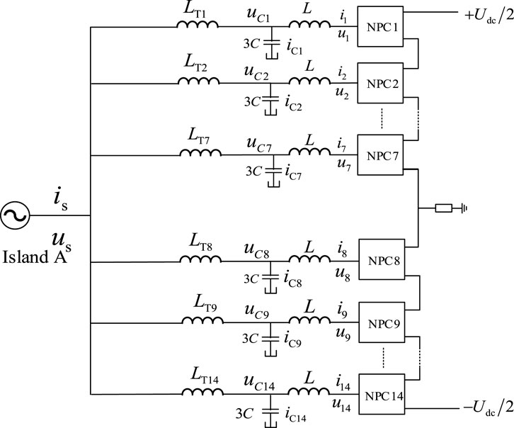
The mathematical model of the C-NPC power system is established, the equivalent topology of which is shown in Figure 3. The equivalent inductance of the coupling transformer in each winding is LTn. The series inductance of the filter circuit is L, and the parallel capacitance of each phase is C. After circuit simplification, the equivalent capacitance in parallel is 3C.
The mathematical model of a C-NPC primary system in the time domain can be obtained after calculating all variables to the same voltage level.
where us and is are the voltage and current on the AC side, respectively, ucn and icn are the filter capacitor voltage and inflow current of each NPC on the AC side, respectively, and un and in are the port voltage and input current of each NPC, respectively.
In order to facilitate the C-NPC control, Equations 1 and 2 are transformed from an a-b-c coordinate system to a d-q rotating coordinate system by d-q transformation.
where usd, usq, isd, and isq are the d- and q-axis components of the AC voltage and AC current in frequency domain by d-q transformation, respectively, ucnd, ucnq, icnd, and icnq are the d- and q-axis components of the filter capacitor voltage and inflow current of each NPC on the AC side in frequency domain by d-q transformation, respectively, and und, unq, ind, and inq are the d- and q-axis components of the port voltage and input current of each NPC, respectively.
3.2 C-NPC control strategies
A C-NPC controller consists of outer and inner loop current controllers (He et al., 2018; Issa et al., 2018; IEEE Standard for theTesting of Microgrid Controllers, 2018). The active power control of the outer loop controller includes the active power and DC voltage. The reactive power control is reactive power and AC voltage. In order to adapt to the multi-energy operation mode of an island microgrid, the three typical control strategies, Udc/Us, P/Q, and V/f controls, are selected for analysis.
3.2.1 Fixed Udc/Us (STATCOM) control strategy
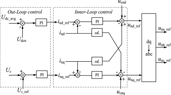
When the C-NPC operates as an auxiliary power source in an island microgrid (the diesel generator can be used as the main control power source), the C-NPC can operate in a fixed Udc/Us (STATCOM) control mode. Among these, DC voltage Udc and AC voltage amplitude Us are the outer loop control quantities. ind_ref、inq_ref、und_ref、unq_ref are the d- and q-axis reference values of the port voltage and input current of each NPC sub-unit. If the number of cascade NPC sub-units is N, with the port voltage at AC side of the C-NPC realigned with the d-axis, then the active power control quantity of the outer loop control is the NPC port voltage Udcn and the reactive power control variable is the AC voltage amplitude Us at the valve side of the transformer. The system control block diagram is shown in Figure 4 below.
When the Udc/Us control system reaches steady state, the following equation relates:
In the above formula, Us and Usref are respectively the AC voltage amplitude and its reference value, Udcn and Udc_ref are the DC port voltage and the reference value of each NPC, and Kn is the equivalent transformer ratio of each winding.
Since the converter introduces DC voltage, the active power input and output equations of the AC and DC sides of the port can be established as follows when the loss of the converter is ignored:
Furthermore, the active power P and reactive power Q emitted by C-NPC can be expressed thus:
From Equations 3 and 4, there are 114 effective equations of the C-NPC mathematical model transformed by dq—144 unknowns in total:
By connecting the lines (Equations 5–10), we can see that 46 effective equations are increased under constant Udc/Us control. Udc is a known quantity because constant voltage control is adopted, and the active and reactive power emitted by C-NPC is also a known quantity, so 30 unknowns are increased under the control strategy,
and 160 equations in total—174 unknown variables. Obviously, the number of equations is smaller than the number of unknowns, and the equations have infinite solutions, so that after the system constraints are satisfied, there are still unknown variables satisfying the constraint condition of Equation 9. When the system is disturbed, the controller will adjust repeatedly between the unsteady conditions of the system, risking system instability.
For an NPC, the output power of the DC side is equal to the active power input of the AC side plus the internal loss of NPC. Ignoring the internal loss, the equation of the AC side active power input and DC side power output of the port is established as Equation 9.
Since the active power control is fixed voltage control, the voltage of each NPC on the DC side can be effectively controlled. From the DC side, all NPC are in series, so the current of all NPC is idc. Since the reactive power control is fixed AC voltage, the voltage Ucn on the transformer valve side can also be effectively controlled.
According to Equation 9, the d-axis current on the AC side can be effectively controlled. However, there is no relationship to effectively control the q-axis current at the AC side of each port. In order to realize the current sharing control on the AC side of NPC, it is necessary to add the q-axis current sharing control to fixed Udc/Us control.
3.2.2 Fixed P/Q control strategy
When the diesel generator and C-NPC DC system jointly supply power to the microgrid and the system frequency is set by the diesel generator, C-NPC can operate in a constant P/Q control mode. Compared with the fixed Udc/Us control, only the outer loop control of the fixed P/Q control changes to the fixed active power P and reactive power Q. The control block diagram is shown below.
When a constant P/Q system reaches steady state, the equation is:
Since the control target introduces active and reactive power, the following power equation constraints can be further established:
Similarly, based on the above method, combining Equations 3, 4, and 10–12 shows that there are 172 effective equations and 172 unknown variables under constant P/Q control. Obviously, the number of equations is equal to the number of unknowns, and the solution of the equation is unique, so there are unique parameters to make the controller stable.
Based on Equation 9, since the active power control adopts fixed active power control, the right side of each NPC equation is equal to P/N when the system is in steady state. Considering that each NPC on the DC side is in series and the right side of Equation 9 is a constant value idc, the port voltage can be effectively controlled on the DC side. The current of each NPC on the AC side can be effectively controlled due to the fixed P/Q control. Thus, no additional control scheme is required.
3.2.3 Fixed V/f control strategy
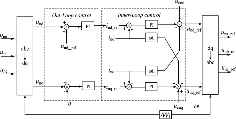
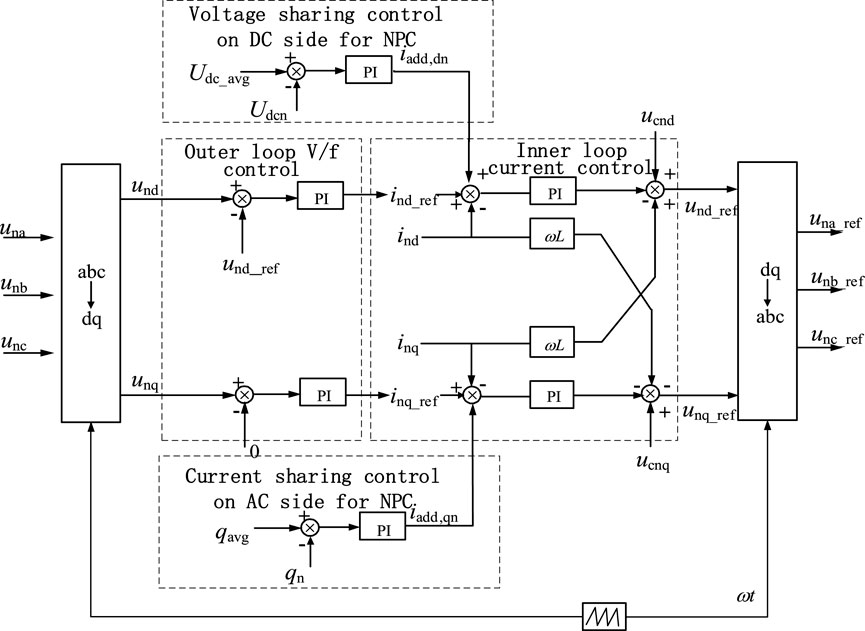
When there is no diesel generator in the microgrid or when the diesel generator is out of operation, there is no power supply that can support the frequency in the microgrid, and the island microgrid needs AC voltage to support its normal operation. Therefore, in order to support the frequency and maintain the stable operation of the system, C-NPC needs to provide reliable AC voltage. Consequently, the C-NPC system adopts the fixed V/f control strategy in isolated island operation mode. The control block diagram is shown below.
When the V/f control system reaches steady state, the constraints are:
In this case, by combining Equations 3, 4, 10, and 13, the number of effective equations in island mode is 144, and the number of V/f control unknowns in island mode is 172. Obviously, there are also infinitely many solutions, and the system has the risk of instability.
For the V/f control, the active power control is the AC voltage, but there will also be a voltage deviation between NPC on the DC side under the isolated island operation mode. The reactive power control is the fixed frequency, and the current on the AC side is not effectively controlled.
4 Design of C-NPC additional control strategies
To solve the problem that the AC measuring current cannot be effectively controlled in Udc/Us control, the AC measuring current equalization control is designed. For the additional current equalization control under V/f control, the Q-axis current can be effectively controlled, but the D-axis current and DC voltage have not been effectively controlled, so the DC side voltage equalization strategy was designed.
4.1 Current sharing control on AC side for C-NPC
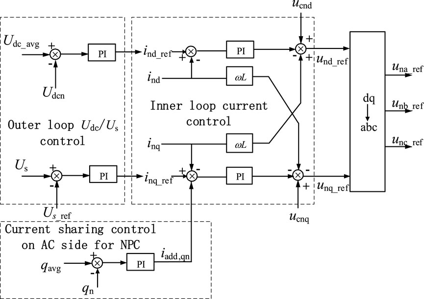
This control is to keep the q-axis current of each NPC unit balanced by controlling the reactive power. The target value is the total reactive power divided by the number of NPC units—the average reactive power of an NPC unit. The q-axis additional input reference current iadd,qn of the inner loop current control can be obtained by PI algorithm. The control block diagram of the improved fixed Udc/Us is shown in Figure 7, after adding the current sharing control. The control expression can be derived as:
By adding the current sharing control to each NPC in the original fixed Udc/Us control, the inq expression in Equation 4 can be replaced by Equation 14, and the additional current equation iadd,qn is introduced.
By introducing Equation 14, the q-axis current on the AC side of each port can be effectively controlled. Thus, under the original fixed Udc/Us control strategy, by adding the NPC current sharing control strategy on the AC side, the possible instability risk of the control system will be effectively eliminated.
4.2 Voltage sharing control on the DC side for C-NPC
The goal of this control is to keep the DC port voltage of each NPC unit balanced. The target value is the total DC voltage divided by the number of NPC units, or the NPC unit average DC voltage. The d-axis additional input reference current iadd,dn of the inner loop current control can be obtained by PI control algorithm. The control block diagram of the improved fixed V/f is shown in Figure 8, after adding the current and voltage sharing controls. The control expression can be derived as:
Similarly, under the fixed V/f control in isolated island operation, adding both of the voltage sharing control on DC side and the current sharing control on AC side between NPC units—adding Equations 14 and 15—the voltage deviation on the DC side and the current on the AC side can be effectively controlled among NPC units. Thus, the potential instability problem in the fixed V/f control can be solved.
5 Simulation verification
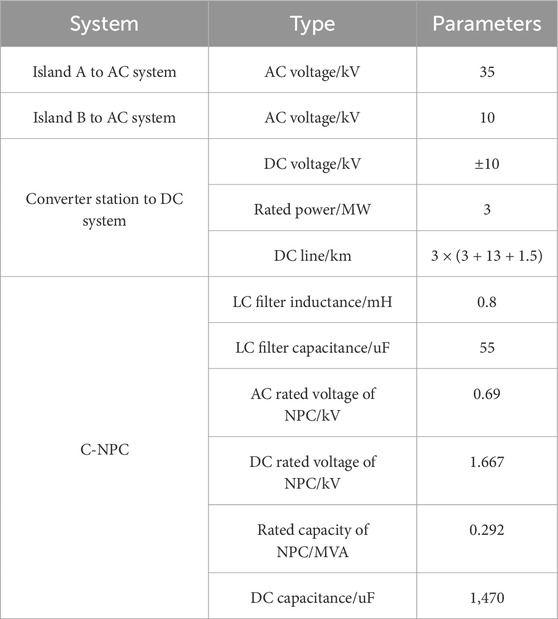
Based on PSCAD, a one-terminal C-NPC island system was built to verify the effectiveness of the proposed additional control strategy. Furthermore, taking the island’s actual engineering as an example, the two-terminal C-NPC island interconnection system simulation tests under three typical operation modes were carried out to verify the operational performance of the system. The parameters of the AC/DC system and the two converter stations on Islands A and B are given in Table 1.
5.1 Additional control scheme in a one-terminal system
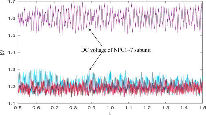
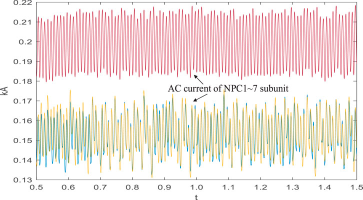
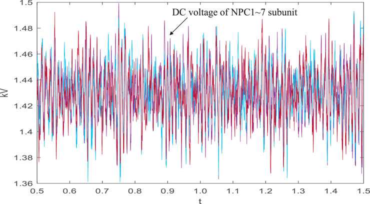
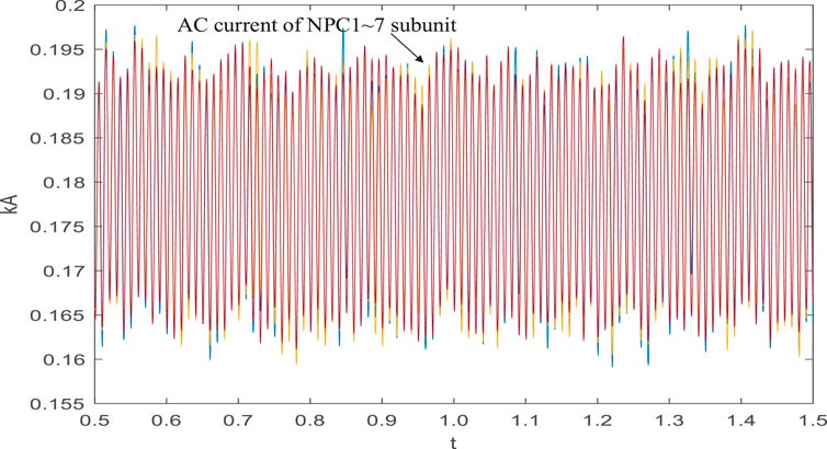
With the typical fixed V/f control strategy without any additional strategy used for the one-terminal C-NPC system control, the voltages on the DC side and A-phase RMS current on the AC side of NPC are shown in Figures 9 and 10. The DC side voltages of each NPC port are unbalanced, and the AC side currents show a divergence trend, leading to uneven voltage and current stress of the NPC power device, thus threatening device safety and the stable operation of system. After adding the additional control strategies such as the voltage and current sharing control proposed here, the DC-side voltage and AC-side current of each NPC are shown in Figures 11 and 12, respectively.
By adding the additional control strategy, the DC voltage and AC current of each NPC were equalized, and the potential problem affecting system stability could be solved.
5.2 STATCOM operation in one-terminal system
The one-terminal system adopts the fixed DC voltage and reactive power control under STATCOM operation and adjusts the voltage of the local AC system by sending or absorbing reactive power. The simulation waveforms of the Island B converter station under STATCOM operation are given in Figures 13–16, including the DC voltage and AC reactive power of cascaded/single sub-units.
Under STATCOM operation and the proposed control, the system can control the DC voltage and AC reactive power of cascaded sub-units and balance the DC voltage and AC reactive power of each sub-unit according to the set value of the control target. This steady state control accuracy is about 2%, and the system runs well.
5.3 Grid-connected operation in two-terminal system
The Island A converter station at the sending end uses the fixed DC voltage and reactive power control, and the Island B converter station at the receiving end adopts the fixed active power and reactive power control. Figures 17–19 show the simulation waveforms of converter stations under the grid-connected operation, including the DC voltage, active power, and reactive power of cascaded sub-units.
In grid-connected operation mode, the system can control the DC voltage, AC active power, and reactive power of cascaded sub-units, and balance the DC voltage, AC active power, and reactive power of each sub-unit through the set value of the proposed control target. This steady state control accuracy is about 2%, and the system runs well.
5.4 Isolated island operation in two-terminal system
Island A converter station at the sending end uses fixed DC voltage and reactive power control, and Island B converter station at the receiving end adopts the isolated island outer loop control to realize the voltage and frequency control of the island grid. Figures 20–23 show the simulation waveforms of converter stations under this operation, including the voltage and frequency of an isolated island grid, and the DC voltage and load power of cascaded sub-units, respectively.

Figure 23. Load power of a single sub-unit of the isolated island power grid of Island B converter station.
In the isolated island operation mode, the system can control the DC voltage, load power, and AC voltage/frequency of cascaded sub-units and balance the DC voltage and load of each sub-unit by the set value of the proposed control target. This steady-state control accuracy is about 2%. The total harmonic distortion (THD) of the isolated island power grid AC voltage is 2.1%, less than the 4% upper limit stipulated by relevant national standards, indicating good system operation performance.
6 Conclusion
In order to improve the power supply reliability of a multi-energy microgrid on an island and promote the overall utilization rate of clean energy on an island regional grid, we propose a new cascade three-level DC interconnection system scheme and multi-mode control technology. For a flexible island interconnection project, we have analyzed the possible problems of the system with various C-NPC control strategies . To deal with the problems of controls, we designed corresponding additional control strategies for DC voltage sharing and AC current sharing among C-NPC modules. The effectiveness of proposed additional control strategies is verified based on PSCAD. The simulation of typical system operations was carried out, including STATCOM operation in a one-terminal system and grid-connected operation and isolated island operation in a two-terminal system. The simulation test results verify the good operating characteristics of the C-NPC DC system. The main conclusions are as follows.
C-NPC topology is more suitable for the application demands of low-cost and compact VSC-HVDC converter stations for small-capacity island interconnection systems.
According to the simulation results, the control accuracy of each parameter of the system under STATCOM, grid-connected, and isolated island operations is maintained at approximately 2%. Moreover, the electrical parameters of C-NPC sub-units or each single NPC sub-unit are kept balanced, verifying good system operation performance.
A C-NPC island HVDC interconnection system can be applied to medium and low voltage DC distribution networks with a high proportion of new energy, such as DC load industrial parks and photovoltaic-storage DC-flexible distribution energy. This can promote the reduction of fossil energy consumption, achieve clean energy such as solar energy and wind energy to replace fossil energy and provide new solutions.
Data availability statement
The original contributions presented in the study are included in the article/supplementary material; further inquiries can be directed to the corresponding author.
Author contributions
XL: Methodology, Writing–review and editing. ZW: Supervision, Writing–review and editing. SL: Conceptualization, Writing–review and editing. BB: Supervision, Writing–review and editing. XD:Conceptualization, Methodology, Writing–review and editing.
Funding
The authors declare that financial support was received for the research, authorship, and/or publication of this article. This research was funded by the State Grid Ningxia Electric Power Company Technology Project Support (5229JY22000H) and Ningxia Natural Science Foundation (2023A1155).
Conflict of interest
Author XL, ZW, SL, BB State Grid Ningxia Electric Power Co.Ltd.
Author XD was employed by Beijing DC T&D Engineering Technology Research Center (NARI China-EPRI Electrical Engineering Co., Ltd.).
The authors declare that this study received funding from State Grid Ningxia Electric Power Company of China. The funder had the following involvement in the study: design, collection, analysis, interpretation of data, the writing of this article, and the decision to submit it for publication.
Publisher’s note
All claims expressed in this article are solely those of the authors and do not necessarily represent those of their affiliated organizations, or those of the publisher, the editors, and the reviewers. Any product that may be evaluated in this article, or claim that may be made by its manufacturer, is not guaranteed or endorsed by the publisher.
References
Hao, W. (2015). Application of VSC-HVDC technology in the field of islands power supply. South. Energy Constr. 2 (S1), 46–49. doi:10.16516/j.gedi.issn2095-8676.2015.S1.010
He, J., Pan, Y., Liang, B., and Wang, C. (2018). A simple decentralized islanding microgrid power sharing method without using droop control. IEEE Trans. Smart Grid 9 (6), 6128–6139. doi:10.1109/tsg.2017.2703978
IEEE Standard for the Testing of Microgrid Controllers (2018). “IEEE standard for the testing of microgrid controllers,” in Ieee std 2030.8-2018, 1–42. doi:10.1109/IEEESTD.2018.8444947
Issa, W. R., El Khateb, A. H., Abusara, M. A., and Mallick, T. K. (2018). Control strategy for uninterrupted microgrid mode transfer during unintentional islanding scenarios. IEEE Trans. Industrial Electron. 65 (6), 4831–4839. doi:10.1109/tie.2017.2772199
Kanchev, H., Lazarov, V., and Francois, B. (2012). “Environmental and economical optimization of microgrid long term operational planning including PV-based active generators,” in 2012 15th international power electronics and motion control conference (EPE/PEMC). LS4b-2.1-1-LS4b-2.1-8.
Leon, J. I., Vazquez, S., and Franquelo, L. G. (2017). Multilevel converters: control and modulation techniques for their operation and industrial applications. Proceed. Ieee. 105 (11), 2066–2081. doi:10.1109/jproc.2017.2726583
Li, F., Zhou, M., and He, Y. (2015). Design scheme of system access and converter station of Nanao VSC-MTDC demonstration project. South. Power Syst. Technol. 9 (1), 58–62. doi:10.13648/j.cnki.issn1674-0629.2015.01.010
Li, Y., and Ma, Z. (2011). The extension and application of flexible DC technology in island power transmission. ZHEJIANG Electr. Power 30 (07), 26–29. doi:10.3969/j.issn.1007-1881.2011.07.008
Li, Y., Xu, J., Yang, H., Cheng, Z., Shi, K., and Xu, L. (2020). Overview and prospect of multilevel converter topology. Electr. Mach. Control 24 (09), 1–12. doi:10.15938/j.emc.2020.09.001
Lin, L., Zou, Y., and Zhong, H. (2005). Study of control system of diode-clamped three-level inverter. Proc. CSEE 15, 33–39. doi:10.3321/j.issn:0258-8013.2005.15.007
Mao, M., Qian, C., and Ding, Y. (2018). Decentralized coordination power control for islanding microgrid based on PV/BES-VSG. CPSS Trans. Power Electron. Appl. 3 (1), 14–24. doi:10.24295/cpsstpea.2018.00002
Qiao, W., and Mao, Y. (2011). Overview of Shanghai flexible HVDC transmission demonstration project. East China Electr. Power 39 (7), 1137–1140.
Rao, H., Zhou, Y., Li, W., Zou, C., and Wang, Z. (2023). Engineering application and development prospect of VSC-HVDC transmission technology. Automation Electr. Power Syst. 47 (01), 1–11. doi:10.7500/AEPS20220330004
Shi, S., Zhu, W., Wen, S., Wang, H., and Yang, W. (2024). “Two-stage optimal operation of low-carbon island microgrid with high penetration of renewable energy,” in 2024 IEEE 7th international electrical and energy conference (CIEEC) (IEEE), 4699–4703. doi:10.1109/CIEEC60922.2024.10583688
Singh, B., Pathak, G., and Panigrahi, B. K. (2018). Seamless transfer of re-newable-based microgrid between utility grid and diesel generator. IEEE Trans. Power Electron. 33 (10), 8427–8437. doi:10.1109/tpel.2017.2778104
Sun, P., Tian, Y., Pou, J., and Konstantinou, G. (2022). Beyond the MMC: extended modular multilevel converter topologies and applications. IEEE Open J. Power Electron. 3, 317–333. doi:10.1109/OJPEL.2022.3175714
Tafreshi, S., Zamani, H., Ezzati, S., Baghdadi, M., and Vahedi, H. (2010). “Optimal unit sizing of distributed energy resources in microgrid using genetic algorithm,” in Electrical engineering (ICEE), 2010 18th Iranian conference on (IEEE), 836–841. doi:10.1109/IRANIANCEE.2010.5506961
Tang, G., He, Z., and Peng, H. (2013). Research, application and development of VSC-HVDC engineering technology. Automation Electr. Power Syst. 37 (15), 3–14. doi:10.7500/AEPS20130224003
Wu, W., Chen, Y., Luo, A., Zhou, L., Zhou, X., Yang, L., et al. (2018). DC impedance modeling, oscillation analysis and suppression method for VSC-HVDC system in the field of islands power supply. Proc. CSEE 38 (15), 4359–4368+4636. doi:10.13334/j.0258-8013.pcsee.171140
Yuan, K., Xu, F., and Li, J. (2018). Research on local natural gas power development and flexible HVDC connection with mainland for islands. South. Energy Constr. 5 (04), 73–77. doi:10.16516/j.gedi.issn2095-8676.2018.04.011
Zhang, K. , Wang, G., Geng, X., Hu, S., Liu, J., Jia, Z., et al. (2021). “A seamless soft transfer-ring method for microgrid energy storage converter[C],” in Proceedingsof the 2021 13th international conference on measuring technology and mechatronics automation (Beihai, China: IEEE), 150–154. doi:10.1109/ICMTMA52658.2021.00041
Keywords: island, multi-energy microgrid, DC interconnection system, flexible multi-mode control, carbon reduction
Citation: Liu X, Wang Z, Liu S, Bai B and Du X (2024) Research on a DC interconnection system based on a cascaded three-level converter for an island multi-energy microgrid. Front. Energy Res. 12:1495854. doi: 10.3389/fenrg.2024.1495854
Received: 13 September 2024; Accepted: 23 October 2024;
Published: 27 November 2024.
Edited by:
Qiang Yu, China Agricultural University, ChinaReviewed by:
Xuezhi Wu, Beijing Jiaotong University, ChinaYin Jingyuan, Chinese Academy of Sciences (CAS), China
Copyright © 2024 Liu, Wang, Liu, Bai and Du. This is an open-access article distributed under the terms of the Creative Commons Attribution License (CC BY). The use, distribution or reproduction in other forums is permitted, provided the original author(s) and the copyright owner(s) are credited and that the original publication in this journal is cited, in accordance with accepted academic practice. No use, distribution or reproduction is permitted which does not comply with these terms.
*Correspondence: Xiangnan Du, amF5ZHhuQDE2My5jb20=
 Xiaomin Liu1
 Xiangnan Du

