 Zhigang Pei1
 Xin Yan
 Yifang Jin
- 1Shaoxing Power Supply Company, State Grid Zhejiang Electric Power Co., Ltd, Shaoxing, China
- 2College of Electrical and Information Engineering, Hunan University, Changsha, China
This paper investigates on dynamic topology reconfiguration of distribution networks to enhance PV hosting capacity. Firstly, a dynamic topology reconfiguration model of distribution networks considering N-1 security constraints is proposed to accommodate intermittent PV generation, and thus high penetration of renewable resources can be ensured to satisfy operational requirements under both normal and fault conditions with load transfer of feeders. Then, a hosting capacity enhancement strategy is presented to decrease risks of voltage and line overloading with reactive power flexibility of energy storage inverters, and is implemented to enhance the maximum hosting capacity of distributed renewable energy sources. Finally, simulation results have validated the effectiveness of the proposed method for PV hosting capacity enhancement of distribution networks.
1 Introduction
Global low-carbon and environmental concerns have enabled various distributed renewable energy sources (RESs), such as solar photovoltaics (PV), wind and hydro power, to be grid-connected with gradually increasing penetration in distribution networks (Wang S. et al., 2020). However, technical problems such as nodal voltage violation, reverse overload and power quality deviation caused by large-scale distributed RESs have become increasingly prominent (Alam et al., 2015; Hu et al., 2021; Martinenas et al., 2017; Jia et al., 2024). Numerous methodologies to increase hosting capacity of distribution networks, including demand response of flexible loads (Ding et al., 2023; Zhang et al., 2023), standby energy storage systems (Zheng and Jin, 2021; Jia et al., 2022; Zheng et al., 2023), have been reported. Nevertheless, the existing research fails to fully make use of the potential of reactive power regulation of flexible resources. Also, the N-1 security issues have not been considered as boundary conditions for the evaluation of PV hosting capacity. Therefore, this paper focuses on providing insightful perspectives and discussions on the dynamic topology reconfiguration of distribution networks for PV hosting capacity enhancement.
The main contributions of this work can be twofold as listed: (1) A dynamic topology reconfiguration model of distribution networks considering N-1 security constraints is proposed to accommodate intermittent PV generation, and thus high penetration of renewable resources can be ensured to satisfy operational requirements under both normal and fault conditions with load transfer of feeders; (2) A hosting capacity enhancement strategy is presented to decrease risks of voltage and line overloading with reactive power flexibility of energy storage inverters, and is implemented to enhance the maximum hosting capacity of distributed renewable energy sources.
2 Evaluation model of PV hosting capacity considering diversified flexibility resources
This paper proposes a strategy to enhance the PV hosting capacity of distribution networks by considering the reactive power flexibility of energy storage systems (Dubey and Santoso, 2017; Wang et al., 2021). Based on the principle of four-quadrant operation of energy storage converters, the reactive power feasible region of energy storage is obtained using the apparent power and active power as boundaries (Li et al., 2021; Yan et al., 2019). In Figure 1A, the blue rectangle represents the feasible region of the energy storage system’s active and reactive power. Then, using Minkowski summation, the feasible range for the active power and energy of a single electric vehicle are combined to obtain the feasible range for a cluster of electric vehicles. By jointly planning the cluster of electric vehicles and the energy storage system (Masiello et al., 2024; Ju et al., 2023), this strategy aims to reduce the risk of voltage violations and line overloads in the distribution network, thereby improving the PV hosting capacity of distribution networks. The four-quadrant operation of energy storage and the cluster of electric vehicles are illustrated in Figure 1A.
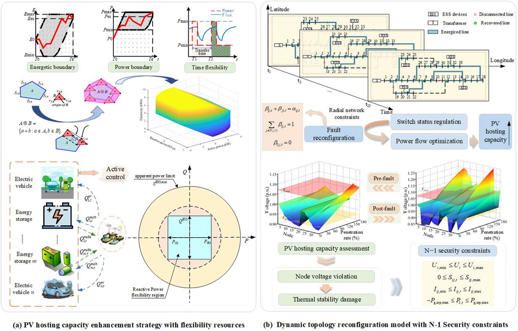
Figure 1. A model of distribution networks for PV hosting capacity enhancement. (A) PV hosting capacity enhancement strategy with flexibility resources. (B) Dynamic topology reconfiguration model with N-1 Security constraints.
To accurately evaluate the maximum hosting capacity of the PV system in distribution networks, the optimization objective is to maximize the total installed capacity of photovoltaic systems connected to distribution networks (Yuan et al., 2024), ensuring grid safety while accommodating the maximum number of distributed PV systems. The objective function is shown in Equation 1:
where
Power balance constraints are shown in Equations 2–5:
Line power flow limit constraint is shown in Equation 6:
Energy storage operation constraints are shown in Equation 7 through Equation 9:
where
Energy storage operation constraints: considering the energy storage power and power operation constraints, the feasible range of energy storage active power is obtained, and the adjustable feasible range of reactive power is obtained under the constraint of apparent power. The energy storage operation constraints are to be satisfied as follows:
where
Considering the inherent power and energy limitations of the battery, the feasible domain for characterizing the active power over multiple time periods by the passage of time is shown in Equations 10–17:
where
Based on the apparent power constraint of the energy storage battery, the feasible domain of reactive power is derived, as shown in Equations 18, 19:
where
where
The feasible region constraints for the virtual battery power of the clustered electric vehicles are to be satisfied (Zhao et al., 2020; Xin et al., 2024) as shown in Equations 22–25:
where
The flexibility of cluster electric vehicles can be characterized using the Minkowski method by summing the power and energy boundaries of single electric vehicle (Michaelides, 2020), and the comprehensive power and energy boundaries are shown in Equations 26–31:
where
where
However, due to effect of switching on and off the electric vehicle engine on the power range of the integrated model in successive time periods, the corresponding energy coupling on the time axis cannot be achieved (Li et al., 2017). To address this issue, a random variable
where
3 Optimal dynamic network reconfiguration strategy for PV hosting capacity enhancement
In this paper, considering the intermittency of PV generation and operational requirements of distribution networks in normal and fault conditions, a dynamic topology reconfiguration model of distribution networks with N-1 safety constraints (Cao et al., 2024), based on network radial constraints (Lei et al., 2020), switching frequency constraints, post-fault switching frequency constraint, branch current constraints, and maximum PV capacity as the objective function is developed. In the context of N-1 security, the model dynamically reconfigures distribution networks by changing the switching state in real time, ensuring the radial shape of distribution networks, solves the load transfer problem after equipment or line fault, and enhances the PV hosting capacity of distribution networks with variable topology. The principle of dynamic topology reconfiguration of distribution networks and N-1 security constraints is shown in Figure 1B.
1) To ensure that distribution networks maintain a radial structure in both normal and fault conditions, a state variable
where
2) During the reconfiguration process, excessive switching operations can negatively impact the lifespan of the equipment, as well as lead to increased power outage losses, equipment degradation, and higher maintenance costs. Therefore, reconfiguration process of distribution networks must satisfy the following switching frequency constraints as shown in Equations 41, 42 (Yadav and Jain, 2016):
where
3) After a fault occurs in the equipment or line, in order to ensure that the power supply of distribution networks can be restored quickly during the reconfiguration process, it is necessary to transfer the entire feeder’s load with the minimum number of switching operations. The switching frequency constraint after the fault is shown in Equation 43:
4) To ensure the thermal stability of equipment and lines, the current from distributed PV access should not exceed the thermal stability limits of the grid equipment and lines to prevent overload. Therefore, the branch current limitation constraint for the distribution networks is shown in Equation 44:
where
Due to the use of absolute value operators in the constraints (Equations 41–43), variables
4 Discussion and conclusions
The evaluation of distributed photovoltaic hosting capacity in distribution networks has four different scenarios. Scenario 1 is the method proposed in this paper. Scenario 2 involves the active control of flexibility resources such as energy storage and electric vehicles, along with the dynamic reconfiguration of network topology, based on normal operating conditions, and without considering the N-1 contingency state. Scenario 3 does not consider the dynamic reconfiguration of network topology, but includes the active control of flexible resources such as energy storage and electric vehicles. Scenario 4 does not include the active control of flexibility resources or electric vehicles, but considers the dynamic reconfiguration of network topology as well as the normal operating state and the N-1 contingency state. The distributed photovoltaic hosting capacities of the distribution network obtained from the simulation of these four scenarios are shown in Figure 2A.
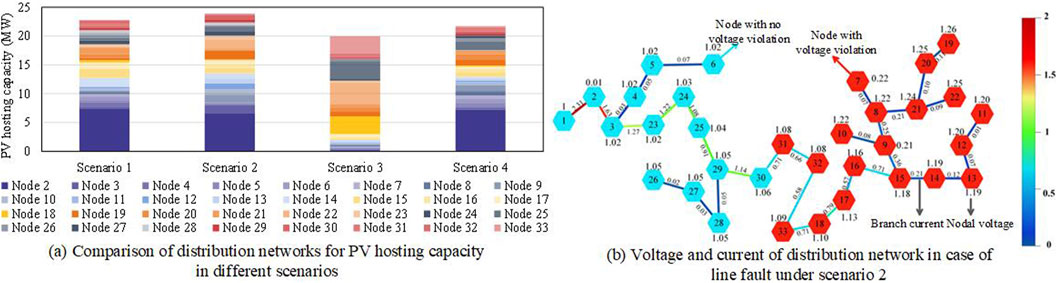
Figure 2. Comparison of results of PV hosting capacity DESS in distribution networks for different scenarios. (A) Comparison of distribution networks for PV hosting capacity in different scenarios. (B) Voltage and current of distribution network in case of line fault under scenario 2.
As shown in Figure 2A, the column in Figure 1 represents the cumulative sum of the PV hosting capacity of each node in different scenarios. Scenario 1 improves the overall photovoltaic (PV) hosting capacity of the distribution networks by 14.27% compared to scenario 3 due to the consideration of dynamic topology reconfiguration of distribution networks to optimize the power flow distribution in distribution networks and alleviate issues of equipment and line overloads. It also shows a 4.92% improvement compared to scenario 4 due to the use of energy storage inverters for reactive power control. Although there is a reduction in the overall PV hosting capacity compared to scenario 2, it ensures the safe operation of the grid under the N-1 fault condition. Therefore, scenario 1 achieves an overall optimal distributed PV hosting capacity, indicating that the combination of dynamic network topology reconfiguration and active control of flexible resources not only enhances the effective utilization of energy, but also improves the distributed PV hosting capacity of distribution networks.
Figure 2B represents a 33-node distribution network, where blue nodes indicate normal voltage, red nodes indicate voltage violation, and branches of different colors represent different current values according to the color swatches on the right side. From Figure 2B, without considering the N-1 contingency state (scenario 2), fault reconfiguration can be performed after a line fault to enable load transfer at the nodes. However, failure to consider the N-1 security leads to voltage violations at certain nodes and overloads in some branches after fault reconfiguration. The N-1 security helps ensure that other lines are not overloaded during a fault, thereby preventing cascading failures. Therefore, the consideration of N-1 contingency in the evaluation of distribution networks for PV hosting capacity enhances the operational safety of the distribution system and effectively avoids safety issues caused by contingency faults.
An evaluation method for the acceptance capacity of distributed photovoltaics, considering the active regulation of flexible resources and dynamic reconfiguration of the distribution network topology, is proposed. The main conclusions are as follows: 1) The dynamic reconfiguration of network topology and the adjustable potential of flexible resources are comprehensively considered. By optimizing power flow paths and improving grid flexibility, real-time improvements in power flow distribution are achieved, leading to a more uniform distribution of photovoltaic power output throughout the grid. The proposed method makes it possible to increase the acceptance capacity of the distribution network by more than 14.2%. 2) In the evaluation process of photovoltaic acceptance capacity in the distribution network, the safety of system operation is improved by considering N-1 contingency scenarios. It is ensured that the optimized photovoltaic capacity can be delivered normally, even when line faults occur, effectively avoiding safety issues caused by anticipated faults.
Data availability statement
The raw data supporting the conclusions of this article will be made available by the authors, without undue reservation.
Author contributions
ZP: Writing–original draft, Writing–review and editing. JC: Conceptualization, Writing–original draft. ZZ: Formal Analysis, Writing–review and editing. WL: Formal Analysis, Writing–review and editing. XY: Data curation, Writing–original draft. YJ: Data curation, Writing–original draft.
Funding
The author(s) declare that no financial support was received for the research, authorship, and/or publication of this article.
Conflict of interest
Authors ZP, JC, ZZ and WL were employed by Shaoxing Power Supply Company, State Grid Zhejiang Electric Power Co., Ltd.
The remaining authors declare that the research was conducted in the absence of any commercial or financial relationships that could be construed as a potential conflict of interest.
Generative AI statement
The author(s) declare that no Generative AI was used in the creation of this manuscript.
Publisher’s note
All claims expressed in this article are solely those of the authors and do not necessarily represent those of their affiliated organizations, or those of the publisher, the editors and the reviewers. Any product that may be evaluated in this article, or claim that may be made by its manufacturer, is not guaranteed or endorsed by the publisher.
References
Alam, M. R., Muttaqi, K. M., and Bouzerdoum, A. (2015). Characterizing voltage sags and swells using three-phase voltage ellipse parameters. IEEE Trans. Industry Appl. 51, 2780–2790. doi:10.1109/TIA.2015.2397176
Cao, Y., Zhou, B., Chung, C. Y., Zhou, K., Zhu, L., and Shuai, Z. (2024). Resilience-oriented coordinated topology reconfiguration of electricity and drainage networks with distributed mobile emergency resources. IEEE Trans. Smart Grid, 1. doi:10.1109/TSG.2024.3419086
Ding, K., Zhang, L., Yang, C. H., and Wang, Z. X. (2023). The optimization analysis of multi-type demand-side flexibility resources for renewable energy accommodation in electrical power systems. Front. Energy Res. 11. doi:10.3389/fenrg.2023.1333872
Dubey, A., and Santoso, S. (2017). On estimation and sensitivity analysis of distribution circuit's photovoltaic hosting capacity. IEEE Trans. Power Syst. 32, 2779–2789. doi:10.1109/TPWRS.2016.2622286
Hu, J. D., Yin, W. B., Ye, C. J., Bao, W. D., Wu, J., and Ding, Y. (2021). Assessment for voltage violations considering reactive power compensation provided by smart inverters in distribution network. Front. Energy Res. 9. doi:10.3389/fenrg.2021.713510
Jia, H. P., Peng, R., Yang, L., Wu, T. Y., Liu, D. N., and Li, Y. B. (2022). Reliability evaluation of demand-based warm standby systems with capacity storage. Reliab. Eng. & Syst. Saf. 218, 108132. doi:10.1016/j.ress.2021.108132
Jia, J. C., Yin, G. L., Sun, L. L., and Abu-Siada, A. (2024). Uncertainty risk assessment of overloading violation based on security region and risk scheduling of active distribution networks. Int. J. Electr. Power & Energy Syst. 155, 109498. doi:10.1016/j.ijepes.2023.109498
Ju, C., Ding, T., Jia, W. H., Mu, C. G., Zhang, H. G., and Sun, Y. G. (2023). Two-stage robust unit commitment with the cascade hydropower stations retrofitted with pump stations. Appl. Energy 334, 120675. doi:10.1016/j.apenergy.2023.120675
Lei, C., Bu, S., Wang, Q., and Liang, L. (2024). Observability defense-constrained distribution network reconfiguration for cyber-physical security enhancement. IEEE Trans. Smart Grid 15, 2379–2382. doi:10.1109/TSG.2023.3334078
Lei, S., Chen, C., Song, Y., and Hou, Y. (2020). Radiality constraints for resilient reconfiguration of distribution systems: formulation and application to microgrid formation. IEEE Trans. Smart Grid 11, 3944–3956. doi:10.1109/TSG.2020.2985087
Li, X., Wang, L., Yan, N., and Ma, R. (2021). Cooperative dispatch of distributed energy storage in distribution network with PV generation systems. IEEE Trans. Appl. Supercond. 31, 1–4. doi:10.1109/TASC.2021.3117750
Li, Z., Jazebi, S., and Leon, F. D. (2017). Determination of the optimal switching frequency for distribution system reconfiguration. IEEE Trans. Power Deliv. 32, 2060–2069. doi:10.1109/TPWRD.2016.2594385
Martinenas, S., Knezović, K., and Marinelli, M. (2017). Management of power quality issues in low voltage networks using electric vehicles: experimental validation. IEEE Trans. Power Deliv. 32, 971–979. doi:10.1109/TPWRD.2016.2614582
Masiello, R., Pandey, S., Chatterjee, D., Harper, A., Jackson, A., and Takayesu, E. (2024). Understanding grid flexibility: flexibility for integrated grid planning with distributed energy resources. IEEE Power Energy Mag. 22, 60–66. doi:10.1109/MPE.2023.3344421
Michaelides, E. E. (2020). Thermodynamics and energy usage of electric vehicles. Energy Convers. Manag. 203, 112246. doi:10.1016/j.enconman.2019.112246
Wang, B., Zhang, C., Dong, Z. Y., and Li, X. (2021). Improving hosting capacity of unbalanced distribution networks via robust allocation of battery energy storage systems. IEEE Trans. Power Syst. 36, 2174–2185. doi:10.1109/TPWRS.2020.3029532
Wang, S., Dong, Z. Y., Chen, C., Fan, H., and Luo, F. (2020a). Expansion planning of active distribution networks with multiple distributed energy resources and EV sharing system. IEEE Trans. Smart Grid 11, 602–611. doi:10.1109/TSG.2019.2926572
Wang, Z. H., Kang, J., Pei, Z. Y., Chen, L., Don, C., Lei, Z., et al. (2020b). Research on the fluctuation characteristics of photovoltaic output based on a multi-weight mixed distribution model. J. Sol. Energy 41 (06), 278–287.
Xiao, J., Zu, G., Gong, X., and Li, F. (2017). Observation of security region boundary for smart distribution grid. IEEE Trans. Smart Grid 8, 1731–1738. doi:10.1109/TSG.2015.2505325
Xin, F., Yang, X., Wang, B. B., Ruilin, X., Fei, M., and Jianyong, Z. (2024). Research on electric vehicle charging load prediction method based on spectral clustering and deep learning network. Front. Energy Res. 12. doi:10.3389/fenrg.2024.1294453
Yadav, M. K., Ravi and Jain, D. K., “Intelligent switching of electrical vehicle with renewable sources to meet the load demand IEEE India international conference on power electronics, 2016, doi:10.1109/IICPE.2016.8079421
Yan, N., Zhang, B., Li, W., and Ma, S. (2019). Hybrid energy storage capacity allocation method for active distribution network considering demand side response. IEEE Trans. Appl. Supercond. 29, 1–4. doi:10.1109/TASC.2018.2889860
Yuan, Y., Ding, T., Chang, X. Y., Jia, W. H., and Xue, Y. X. (2024). A distributed multi-objective optimization method for scheduling of integrated electricity and hydrogen systems. Appl. Energy 355, 122287. doi:10.1016/j.apenergy.2023.122287
Zhang, X. T., Lu, M. X., Li, H., Gao, F., Zhong, C., and Qian, X. (2023). Flexibility resource planning of a power system considering a flexible supply–demand ratio. Front. Energy Res. 11. doi:10.3389/fenrg.2023.1194595
Zhao, H., Baling, F., and Jin, D. (2020). Multi-objective optimization strategy for distribution network considering V2G-enabled electric vehicles in building integrated energy system. Prot. Control Mod. Power Syst. doi:10.1186/s41601-020-0154-0
Zheng, X. D., Gong, Z., Liu, Z. Q., Li, Z. W., Yuan, D., and Jin, T. (2023). Research on Start-stop standby energy storage element participating in wind power filtering under the influence of power quality disturbance. Int. J. Electr. Power & Energy Syst. 145, 108631. doi:10.1016/j.ijepes.2022.108631
Keywords: distribution networks, dynamic reconfiguration, flexibility resources, hosting capacity, renewable energy
Citation: Pei Z, Chen J, Zhang Z, Liu W, Yan X and Jin Y (2024) Opinions on dynamic topology reconfiguration of distribution networks for PV hosting capacity enhancement. Front. Energy Res. 12:1512790. doi: 10.3389/fenrg.2024.1512790
Received: 17 October 2024; Accepted: 25 November 2024;
Published: 16 December 2024.
Edited by:
Tao Ding, Xi’an Jiaotong University, ChinaReviewed by:
Guibin Wang, Shenzhen University, ChinaShiwei Xia, North China Electric Power University, China
Robert Xu, Nanyang Technological University, Singapore
Copyright © 2024 Pei, Chen, Zhang, Liu, Yan and Jin. This is an open-access article distributed under the terms of the Creative Commons Attribution License (CC BY). The use, distribution or reproduction in other forums is permitted, provided the original author(s) and the copyright owner(s) are credited and that the original publication in this journal is cited, in accordance with accepted academic practice. No use, distribution or reproduction is permitted which does not comply with these terms.
*Correspondence: Xin Yan, eXgxODIyOTQ3OTIyM0BobnUuZWR1LmNu