 Wenbin Li
 Lijing Jia1
- 1Guangdong Power Grid Energy Investment Co., Ltd., Guangzhou, China
- 2Chaozhou Power Supply Bureau of Guangdong Power Grid Co., Ltd., Chaozhou, China
With the rapid development of integrated energy systems (IES), the extensive integration of dis-tributed energy and the increasing coupling of multiple energy systems need higher requirements for the coordinated control methods of IESs. This paper proposes a distributed emergency control method for integrated energy systems of industrial parks based on the alternating direction multiplier method (ADMM). Firstly, an optimization scheduling model is established for the integrated energy system in industrial parks. On the basis of minimizing operating costs, the model takes into account the operational constraints of each energy equipment. Secondly, considering the shortage of energy supply, in order to achieve energy transfer between users, a distributed optimization scheduling model for IES of the industrial park is established based on the typical energy structure of users. And a distributed optimization scheduling algorithm for the comprehensive energy system of the industrial park based on ADMM is proposed. Finally, the proposed emergency control method is verified under typical fault scenarios.
1 Introduction
The integrated energy system (IES) is a complex multi energy coupling system, mainly composed of energy networks sub system, energy production sub system, energy conversion sub system, energy storage sub system and energy consumption sub system. The energy networks sub system mainly includes power supply network, cooling supply network, heating supply network, natural gas supply network and other networks. The energy conversion subsystem mainly includes equipment such as combined cooling, heating and power (CCHP), heat pumps, refrigeration and air conditioning. The energy storage sub system mainly includes equipment for storing electricity, heat, cold, and natural gas. The energy consumption sub system mainly consists of multiple types of end users (Cheng et al., 2019). IES has been developing rapidly with its characteristics of high efficiency and environmental protection (Sun et al., 2021).
Therefore, there have been abundant research achievements in the field of IES. In terms of optimizing scheduling, in order to balance the interests of Integrated Energy Operators (IEOs) and users, Cheng et al. (2019) proposed a novel IES optimization framework based on the Stackelberg game of integrated demand response (IDR) to realize the IES optimizing scheduling with uncertain renewable energy generation. By fully utilizing the potential of regional heating networks, a regional heating network model considering time delay and thermal attenuation characteristics was established. Li et al. (2021a) proposed a scheduling model based on opportunity constrained planning for community IES (CIES), which was applied to achieve integrated demand response (IDR) in uncertain environments to minimize system operating costs. The proposed model was applied to explore the potential interaction capabilities of electricity, natural gas, thermal flexible loads, and electric vehicles. On this basis, Li et al. (2021b) analyzed the interactive response characteristics of multiple energy loads. Li et al. (2021b) introduced the horizontal complementary substitution and vertical time shift strategy of electric gas heating cooling, and considers the collaborative complementarity and flexible conversion of multiple energy sources. A stochastic robust optimization operation model of CIES based on comprehensive demand response was established Li et al. (2021a). In order to address the energy management and pricing issues of multi CIES (MCIES), a hierarchical stochastic optimization scheduling method in uncertain environments was proposed (Li et al., 2021).
In terms of reducing carbon emissions, Li et al. (2022) established a comprehensive energy system cooperative game model with cost and carbon emissions as objectives based on the cooperative game theory. And a profit distribution method that combines an improved Shapley value and kernel method was proposed. Wang et al. (2022) proposed an objective function and optimization strategy based on deviation satisfaction. The current carbon tax policy is not ideal in stimulating carbon emissions reduction in this IES. Wang et al. (2022) suggested to increase the current carbon tax threshold price. Zhou et al. (2021) transformed traditional thermal power plants into carbon capture power plants through carbon capture to achieve collaborative optimization of IES. In order to achieve the joint operation of wind power (WP), photovoltaics (PV), heating energy and energy storage, a regional IES (RIES) was constructed (Xuan et al., 2022). Based on carbon capture and carbon footprint tracking technology, effective conversion and utilization of carbon were achieved to meet the requirements of environmental protection, sustainability, and economic development.
In terms of emergency control, due to strong heating electric coupling limitations, uncontrollable renewable energy sources, and limited grid regulation capabilities, the operational performance of IES with a high proportion of renewable energy has deteriorated to increase the reduction of renewable energy. Saxena et al. (2023) pointed the problem of unavailable operating areas in traditional IES and its flexibility improvement mechanism combined with gas boilers, electric boilers, power to gas (P2G), electrical energy storage, and thermal energy storage. Based on the multi type, the flexibility of grid connection of P2G technology and the synergistic effect between different energy carriers were studied (Yan et al., 2023). The results showed that P2G technology can play a role in energy buffering and preventing unpredictable behavior interference. Marzi et al. (2023) proposed a reliability evaluation method for RIES based on intelligent agent communication, which determines the impact of equipment component failures on the system through intelligent agent communication. Li et al. (2016) proposed a reliability assessment method for RIES that includes P2G and gas turbines. Juanwei et al. (2019) constructed a reliability evaluation model for RIES. Based on the proposed model, Juanwei et al. (2019) proposed a topology simplification method for calculating the reliability index of natural gas systems. Lei et al. (2018) proposed a reliability evaluation method for RIES based on the incremental state enumeration method. Guelpa and Verda (2018) modeled and analyzed the impact of pipeline leakage and circulation pump failure on the heating system. And an optimization scheduling method was proposed for the heating system under fault conditions.
With the development of industrial park construction, industrial park construction pays more attention to improving the comprehensive utilization rate of energy Kaisong et al. (2021). Based on the analysis of the problems existing in the industrial park, Kaisong et al. (2021) applied the level comprehensive energy system optimization model to realize a more economic, environmental protection and reasonable energy utilization scheme for the industrial park. In order to provide important reference for designers select typical power load days, Chen et al. (2024) established a hybrid time series model of energy consuming equipment to realize energy consumption characteristics analysis based on data clustering. Considering the price transmission mechanism of multi type energy markets, Jintao and Yang. (2019) proposed the integrated demand response strategy of IES in industrial parks.
In summary, there has been sufficient research on IES in various aspects. There is still relatively little research on energy supply control in industrial park integrated energy systems. This study focuses on the integrated energy systems in industrial parks. The main contributions are as follows:
(1) A distributed emergency control model is proposed for integrated energy systems in industrial parks based on energy transfer. Firstly, a comprehensive energy system is established to optimize objectives, which take into account energy costs, maintenance costs, load loss costs, and user energy transfer costs. Then, establish multi energy bus power balance constraints and multi energy flow device constraints. Finally, the distributed emergency control model for the integrated energy system of industrial parks based on energy transfer is established.
(2) A distributed emergency control solution method is proposed for integrated energy systems in industrial parks based on the alternating direction multiplier method (ADMM). Firstly, an augmented Lagrange function is established. And the original objective function is decomposed into two optimization subproblems. The iterative solution of the subproblems is achieved by calculating the original residuals and dual residuals to realize the distributed emergency control solution method.
2 Distributed emergency control model for IES in industrial park
In this paper, based on the typical energy supply structure a distributed emergency control model for IES of the industrial park is establishing. The model framework is shown in Figure 1. The input of the model includes the market price of energy, the types and capacities of energy supply and storage equipment, and the cooling, heating, and electricity loads of users. The purpose of the model is to realize the emergency control to minimize operating costs for users.
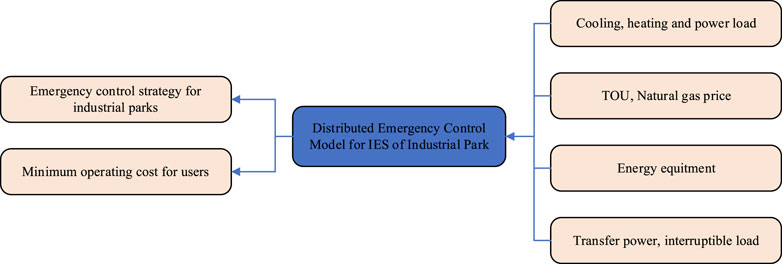
Figure 1. Distributed optimal scheduling model framework of IES in industrial park.
The most common result of energy equipment failure is a shortage of energy supply for users. If energy supply is restored only after the equipment is repaired, it will have a certain impact on users’ production. In order to enhance the reliability of energy supply for users, it is possible to solve the problem by increasing the output of other energy devices or transferring energy between users after the energy equipment failure. If users arbitrarily change the external power purchase plan after formulating daily operation strategies, the gateway power may exceed the limit. So users should prioritize using their own energy equipment for regulation after a failure occurs. If it cannot be met, energy conversion between users should be considered. If the energy supply demand cannot be met, interruptible loads of users should be cut off. The ultimate guarantee is to solve the energy shortage caused by energy equipment failures without changing the external power purchase plan to ensure the normal operation of users.
2.1 Objective function
The distributed emergency control goal of IES in the park is to minimize the daily operating cost for users. The daily operating cost
In Equation 1,
In Equation 2,
The cost of purchasing electricity can be expressed as follows:
In Equation 3,
The operation and maintenance costs of energy supply equipment and energy storage equipment can be expressed as follows:
In Equation 4,
The cost of losses caused by interruptible loads can be expressed as follows:
In Equation 5,
The cost of energy conversion between users can be summarized as follows:
In Equation 6,
2.2 Constraints
2.2.1 Power balance constraints
Due to the consideration of interruptible loads and energy transfer between users, the constraints of the energy bus have changed.
The electrical bus power constraint is shown in Equation 7.
The heating bus balance constraint is shown in Equation 8.
The cooling bus balance constraint is shown in Equation 9.
In Equations 7–9,
2.2.2 Interruptible load constraints
In Equations 10–12,
2.2.3 Energy conversion constraints
In Equations 13–14,
2.2.4 Operation constraints of various energy equipments
Electric energy storage constraints:
In Equation 15,
Cooling storage equipment constraints:
In Equations 19–22,
For ease of description, the above constraints are uniformly expressed as:
In Equations 23, 24,
In summary, the distributed optimization scheduling model for IES can be obtained in Equation 25.
3 Solution method for distributed emergency control strategy of IES based on ADMM
3.1 Objection function
In this paper, the alternating direction multiplier method is applied to analyze the distributed emergency control solution method for IES in the industrial park. User 1 has the ability to transfer energy, while User 2 and User 3 can accept the energy transferred by User 1. The constraints are shown in Equations 26, 27.
Convert the objective function of User 1 into Equation 28.
An augmented Lagrange function is established based on the alternating direction multiplier method. And the objective function can be decomposed into two optimization problems to solve them.
Equation 29 is the augmented Lagrange function for distributed optimization scheduling of the integrated energy system in the industrial park. And it can be decomposed into the following optimization subproblems.
Transfer sub question 1–1 is shown in Equation 30:
Transfer sub question 1–2 is shown in Equation 31:
Transfer sub question 2–1 is shown in Equation 32:
Transfer sub question 2–2 is shown in Equation 33:
The specific solution process for the distributed emergency control problem of the integrated energy system in the park based on the alternating direction multiplier method is shown in Figure 2.
Step 1: set the initial value of the variable.
Step 2: for iteration time
Step 3: for iteration time
Step 4: update Lagrange multipliers
Step 5: calculate the original residuals and dual residuals according to Equation 36. Judge whether the convergence conditions.

Figure 2. Flow chart of distributed emergency control algorithm.
Where
Step 6: if the convergence condition is met, stop the iteration; otherwise update the iteration number
4 Case study
In this paper, IES with three typical users within of the industrial park for calculation and analysis. The distributed emergency control schematic diagram of the integrated energy system of industrial park is shown in Figure 3.

Figure 3. IES architecture.
For user 1, IES includes central air conditioning (CAC), photovoltaics (PV), electric energy storage (EES), combined heat and power (CHP) and electrical loads (EL). For user 2, IES includes CAC, PV, EES, dual working condition refrigeration machine (DWCRM), ice cooling storge (ICS), interruptible cooling load (ICL), and EL. For user 3, IES includes PV, EES, interruptible electrical load (IEL) and EL.
The interruptible load data of the industrial park is shown in Table 1. The upper limit of power transfer between users is shown in Table 2.
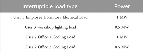
Table 1. User interruptible load.

Table 2. User interruptible load.
The configuration details of energy equipment for the three users are shown in Tables 3–5 respectively. The relevant parameters of energy storage equipment are shown in Table 6.
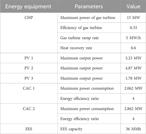
Table 3. Configuration of energy equipment of typical user 1.
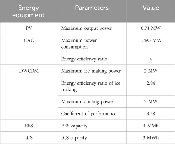
Table 4. Configuration of energy equipment of typical user 2.
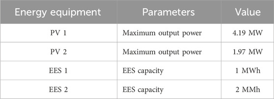
Table 5. Configuration of energy equipment of typical user 3.
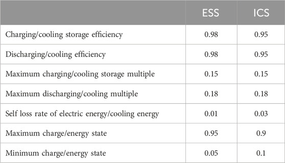
Table 6. Relevant parameters of energy storage equipment.
4.1 Scenario 1
In this scenario, User 1’s partial photovoltaic system experiences a sudden malfunction and requires off grid maintenance. If there is a shortage of energy supply for User 1, the first choice is to increase the output of User 1’s own energy equipment to solve it.
Through the distributed emergency control calculation of the comprehensive energy system in the park, the emergency control result of User 1 is shown in Figure 4, and the operating status of User 1’s CHP unit before and after emergency control is shown in Figure 5.
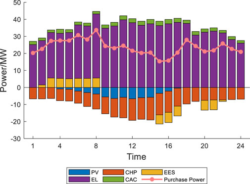
Figure 4. User 1 operation state under emergency control strategy.
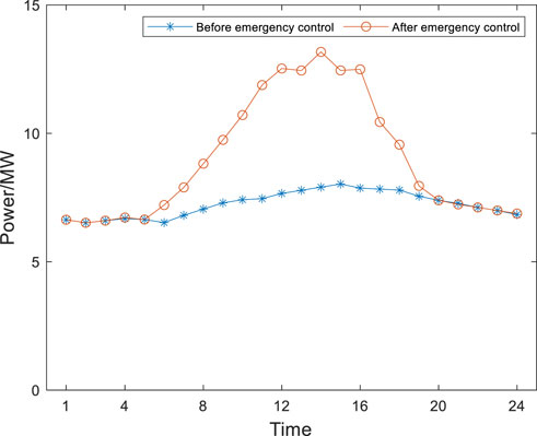
Figure 5. User 1 CHP output comparison.
According to the analysis of the optimization scheduling results for User 1, it can be concluded that the CHP unit increases its power generation from 6:00 to 19:00, and the output of the CHP unit does not exceed the maximum power generation and ramp up power. Therefore, when conducting PV maintenance, User 1’s own CHP can increase the power supply to meet the energy shortage caused by PV maintenance. For the purchased electricity, it is the same before and after emergency control.
4.2 Scenario 2
In this scenario, User 2’s CAC malfunctioned, resulting in a 50% reduction during the 12:00–13:00. If there is a shortage of cooling supply for User 2, the first consideration is to control User 2’s own energy equipment. If the shortage cannot be fully compensated by User 2 themselves, IES should transfer energy from User 1. If it is still not met, consider cutting off the interruptible cooling load. Through the distributed emergency control calculation of IES, the emergency control results of User 2 are shown in Figures 6, 7. The operating status of ICS before and after emergency control is shown in Figure 8, and the operating status of User 1’s CHP unit before and after emergency control is shown in Figure 9.
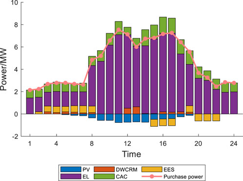
Figure 6. Power load operation of user 2 under emergency control strategy.
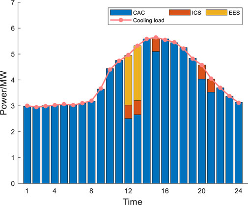
Figure 7. Cooling load operation of user 2 under emergency control strategy.

Figure 8. Comparison of ICS.
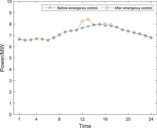
Figure 9. User 1 CHP output comparison.
The cooling shortage caused by the malfunction of CAC between 12:00–13:00 is jointly provided by ICS and DWCRM. The ICS equipment releases cooling to compensate the cooling shortage during the period of 12:00–13:00. However, the maximum cooling power of the ICS during 12:00–13:00 cannot meet the cooling shortage. There-fore, the DWCRM is applied to compensate the remaining energy shortage. The electric power consumed by DWCRM is provided by the CHP of user 1. During the period of 16:00–17:00, the output of ICS cannot meet the cooling load, the CAC will increase its output to meet the cooling load. The increased power consumption of the CAC during this period will be provided by the CHP unit of user 1. The cooling shortage generated by User 2 can be compensated by User 2’s own energy equipment and the energy transferred by User 1. By the application of the proposed strategy, the cooling load can not be reduced.
4.3 Scenario 3
In this scenario, User 3’s PV malfunctioned. The PV output decrease to zero between 14:00–24:00. Through the proposed distributed emergency control method of the IES the emergency control results of user 3 are shown in Figure 10. The operating status of user 1’s CHP unit before and after emergency control is shown in Figure 11. And the interruptible power load cut off by user 3 is shown in Figure 12.
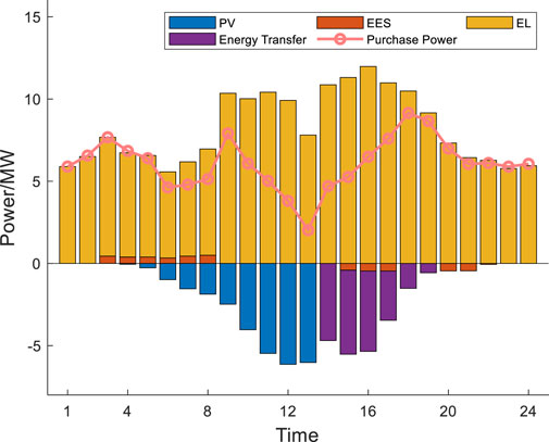
Figure 10. User 3 operation under emergency control strategy.

Figure 11. User 1 CHP output comparison.

Figure 12. Cut off interruptible load.
Due to PV failure, user 3 has a significant power shortage. Even if user 1’s CHP transfers electricity at maximum transfer power during the 14:00–16:00 period, it cannot meet user 3’s power shortage. By the application of the proposed emergency control method for user 3, the interruptible load of user 3 is cut off to ensure the power supply of important equipment for user 3. From 14:00 to 19:00, the CHP of User 1 will transfer power to User 3. And during 14:00. The employee dormitory interruptible load and the workshop lighting interruptible load will be cut off by 1.5 MW. From 15:00 to 16:00, the workshop lighting interruptible load will be cut off by 0.5 MW.
5 Conclusion
In this paper, a distributed emergency control method for IES of the industrial park based on the alternating direction multiplier method is proposed. The optimization objective function of the distributed emergency control method increases the cost of interruptible load loss and energy transfer between users. The interruptible load power and energy transfer power between users is considered. By the application of the alternating direction multiplier method, the emergency control problem is decomposed into two transfer sub problems. By solving the two transfer sub problems separately, the emergency control strategy is obtained. By analyzing three typical energy equipment failure scenarios, the proposed emergency control method is verified.
Data availability statement
The original contributions presented in the study are included in the article/supplementary material, further inquiries can be directed to the corresponding author.
Author contributions
WL: Data curation, Formal Analysis, Methodology, Software, Writing–original draft, Writing–review and editing. LJ: Methodology, Project administration, Writing–original draft, Writing–review and editing. BX: Writing–original draft, Writing–review and editing. RL: Writing–original draft, Writing–review and editing. YH: Writing–original draft, Writing–review and editing.
Funding
The author(s) declare that no financial support was received for the research, authorship, and/or publication of this article.
Conflict of interest
Authors WL, LJ, BX, and RL were employed by Guangdong Power Grid Energy Investment Co., Ltd. Author YH was employed by Chaozhou Power Supply Bureau of Guangdong Power Grid Co., Ltd.
Generative AI statement
The author(s) declare that no Generative AI was used in the creation of this manuscript.
Publisher’s note
All claims expressed in this article are solely those of the authors and do not necessarily represent those of their affiliated organizations, or those of the publisher, the editors and the reviewers. Any product that may be evaluated in this article, or claim that may be made by its manufacturer, is not guaranteed or endorsed by the publisher.
References
Chen, D., Cui, Q., and Ren, P. (2024). Integrated energy system planning for a heavy equipment manufacturing industrial park. Front. Energy Res. 12, 1448362. doi:10.3389/fenrg.2024.1448362
Cheng, Y., Zhang, N., Zhang, B., Kang, C., Xi, W., and Feng, M. (2019). Low-carbon operation of multiple energy systems based on energy-carbon integrated prices. IEEE Trans. Smart Grid 11 (2), 1307–1318. doi:10.1109/tsg.2019.2935736
Guelpa, E., and Verda, V. (2018). Model for optimal malfunction management in extended district heating networks. Appl. energy 230, 519–530. doi:10.1016/j.apenergy.2018.08.024
Jintao, C., and Yang, P. (2019). “Optimized operation of multi-energy system in the industrial park based on integrated demand response strategy,” in 2019 22nd International Conference on Electrical Machines and Systems (ICEMS), Harbin, China, 11-14 August 2019 (IEEE).
Juanwei, C., Tao, Y., Yue, X., Xiaohua, C., Bo, Y., and Baomin, Z. (2019). Fast analytical method for reliability evaluation of electricity-gas integrated energy system considering dispatch strategies. Appl. Energy 242, 260–272. doi:10.1016/j.apenergy.2019.03.106
Kaisong, D., Hu, D.-G., Li, S., Ma, X., Cui, Y., Cui, Q., et al. (2021). “Research on planning and operation of distributed integrated energy system in industrial park,” in 2021 China International Conference on Electricity Distribution (CICED), Shanghai, China, 07-09 April 2021 (IEEE).
Lei, Y., Hou, K., Wang, Y., Jia, H., Zhang, P., Mu, Y., et al. (2018). A new reliability assessment approach for integrated energy systems: using hierarchical decoupling optimization framework and impact-increment based state enumeration method. Appl. Energy 210, 1237–1250. doi:10.1016/j.apenergy.2017.08.099
Li, G., Bie, Z., Kou, Y., Jiang, J., and Bettinelli, M. (2016). Reliability evaluation of integrated energy systems based on smart agent communication. Appl. energy 167, 397–406. doi:10.1016/j.apenergy.2015.11.033
Li, P., Wang, Z., Wang, N., Yang, W., Li, M., Zhou, X., et al. (2021). Stochastic robust optimal operation of community integrated energy system based on integrated demand response. Int. J. Electr. Power and Energy Syst. 128, 106735. doi:10.1016/j.ijepes.2020.106735
Li, Y., Wang, B., Yang, Z., Li, J., and Chen, C. (2022). Hierarchical stochastic scheduling of multi-community integrated energy systems in uncertain environments via Stackelberg game. Appl. Energy 308, 118392. doi:10.1016/j.apenergy.2021.118392
Li, Y., Wang, B., Yang, Z., Li, J., and Li, G. (2021b). Optimal scheduling of integrated demand response-enabled community-integrated energy systems in uncertain environments. IEEE Trans. Industry Appl. 58 (2), 2640–2651. doi:10.1109/tia.2021.3106573
Li, Y., Wang, C., Li, G., and Chen, C. (2021a). Optimal scheduling of integrated demand response-enabled integrated energy systems with uncertain renewable generations: a Stackelberg game approach. Energy Convers. Manag. 235, 113996. doi:10.1016/j.enconman.2021.113996
Marzi, E., Morini, M., Saletti, C., Vouros, S., Zaccaria, V., Kyprianidis, K., et al. (2023). Power-to-Gas for energy system flexibility under uncertainty in demand, production and price. Energy 284, 129212. doi:10.1016/j.energy.2023.129212
Saxena, A., Chandel, A., Dash, A. K., Gupta, S. K., Kumar V, S., and Pandey, J. P. (2023). An effective optimal economic sustainable clean energy solution with reduced carbon capturing/carbon utilization/carbon footprint for grid integrated hybrid system. IEEE Trans. Sustain. Comput. 8 (3), 385–399. doi:10.1109/tsusc.2023.3262982
Sun, J., Ruze, N., Zhang, J., Shi, J., and Shen, B. (2021). Capacity planning and optimization for integrated energy system in industrial park considering environmental externalities. Renew. Energy 167, 56–65. doi:10.1016/j.renene.2020.11.045
Wang, Y., Liu, Z., Cai, C., Xue, L., Ma, Y., Shen, H., et al. (2022). Research on the optimization method of integrated energy system operation with multi-subject game. Energy 245, 123305. doi:10.1016/j.energy.2022.123305
Xuan, A., Shen, X., Guo, Q., and Sun, H. (2022). Two-stage planning for electricity-gas coupled integrated energy system with carbon capture, utilization, and storage considering carbon tax and price uncertainties. IEEE Trans. Power Syst. 38 (3), 2553–2565. doi:10.1109/tpwrs.2022.3189273
Yan, R., Wang, J., Huo, S., Qin, Y., Zhang, J., Tang, S., et al. (2023). Flexibility improvement and stochastic multi-scenario hybrid optimization for an integrated energy system with high-proportion renewable energy. Energy 263, 125779. doi:10.1016/j.energy.2022.125779
Keywords: integrated energy systems, emergency control, alternating direction multiplier method, distributed optimization scheduling, energy transfer
Citation: Li W, Jia L, Xu B, Lu R and Huang Y (2025) Distributed emergency control method for integrated energy system in industrial park based on alternating direction multiplier method. Front. Energy Res. 12:1534825. doi: 10.3389/fenrg.2024.1534825
Received: 26 November 2024; Accepted: 19 December 2024;
Published: 10 January 2025.
Edited by:
Haifeng Qiu, Nanyang Technological University, SingaporeReviewed by:
Yuanyuan Chai, Hebei University of Technology, ChinaQi Liu, Shandong University of Science and Technology, China
Haotian Ge, Hainan Normal University, China
Copyright © 2025 Li, Jia, Xu, Lu and Huang. This is an open-access article distributed under the terms of the Creative Commons Attribution License (CC BY). The use, distribution or reproduction in other forums is permitted, provided the original author(s) and the copyright owner(s) are credited and that the original publication in this journal is cited, in accordance with accepted academic practice. No use, distribution or reproduction is permitted which does not comply with these terms.
*Correspondence: Wenbin Li, bGVld2VuYmluMjAyNEAxNjMuY29t