 Yi Lu1
 Yufei Shang
 Zihan Wang
- 1State Grid Zhejiang Electric Power Research Institute, Hangzhou, Zhejiang, China
- 2School of Automation, Wuhan University of Technology, Wuhan, Hubei, China
There is an urgent need for flexible interconnection in the distribution network. However, due to the complex topology, control strategy and development cost of the existing flexible interconnected device (FID), the existing FID is difficult to be popularized and applied in the above scenarios. In view of the above problems, this paper constructs the FID topology based on the series connection of single-phase control unit and contact switch, and constructs the equivalent circuit of the interconnection line between FID and contact switch in series. The working principle of FID flexible closing loop and power flow control is studied from the dimension of FID output voltage and equivalent impedance. The FID flexible closing loop energy extraction strategy is proposed, and the FID system-level and device-level control strategies with flexible closing loop and power flow control functions are proposed. The simulation results show that the flexible interconnection device based on the proposed topology and control strategy can effectively compensate the pressure difference of the connecting points in the distribution network, regulate the power flow of the active distribution network, and realize the interconnection and mutual assistance of the distribution network.
1 Introduction
With the access of a large number of new energy sources such as wind, solar and energy storage to the distribution network (Gui et al., 2024; Kabirifar et al., 2021), the access of wind and solar resources and the demand for load power in different stations of the distribution network show different characteristics. There are a large number of regional large-scale mutual energy in the interval (Kumar, 2024; Kumar et al., 2023a; Kumar et al., 2020; Satapathy and Kumar, 2020). Through feeder automation technology and distribution network reconfiguration technology, the distribution network can realize the interconnected operation of the station area, and then effectively use the mutual energy of the station area to improve the operation efficiency of the distribution network. The interconnection of the distribution network needs to be closed and unclosed through the sectional switch and the contact switch on the line. However, the conventional closing loop method is limited by machinery, and the response speed is slow and the closed loop impulse current is generated, which not only endangers the safe and stable operation of the distribution network system, but also may cause the protection action to lead to the failure of the closed loop (Liang et al., 2022; Cai et al., 2022; Kumar et al., 2023b).
In order to maximize the absorptive capacity of the distribution network to new energy sources such as wind power and photovoltaic power and the power supply capacity of new flexible loads such as electric vehicle charging piles, researchers have proposed the concept of flexible interconnected device (FID) (Fuad et al., 2020; Deakin et al., 2022). Based on power electronics technology, FID provides flexible power control and flexible interconnection capabilities for distribution networks through flexible and adjustable voltage source converters. Through flexible interconnection technology, non-impact closed loop can be realized, the power flow between phases can be balanced, the constraints of network reconfiguration can be reduced, the operation state of distribution network can be optimized, and the level of wind and solar consumption can be improved (Xu et al., 2022; Alwash et al., 2023; Zolfaghari et al., 2022).
In order to meet the characteristics of different application scenarios of power systems and the requirements of flexible interconnection function modes, scholars at home and abroad have proposed different FID topologies and corresponding control strategies. In Reference Wu et al. (2019), FID based on back-to-back converter is used as the topology of the interconnection device. A multi-mode operation method of power conversion under normal operation and power recovery under single-side fault is proposed, and a smooth switching strategy based on multiple control modes is proposed. In reference Li et al. (2022), a flexible interconnection scheme of distribution network based on the parallel connection of back-to-back converter FID and tie switch is proposed, and a smooth switching control strategy of transfer power supply is proposed. Reference Ouyang et al. (2020) proposed a three-terminal FID topology and a new DC voltage control strategy to improve the flexibility and robustness of DC voltage control. However, the above flexible interconnection scheme using back-to-back FID requires more full-rated power three-phase voltage source converters, resulting in high equipment cost and large device volume, and it is difficult to achieve economic operation in low-voltage distribution network interconnection scenarios. Reference Qi et al. (2023) proposed that FID based on single-phase full-bridge converter can be flexibly interconnected by means of series connection to the system. In the case of islanding, the proposed series SOP can automatically suppress the short-circuit current and restore the power supply voltage. Reference Zhang et al. (2023) proposed a series split multi-port FID and series split arrangement based on cascaded H-bridge structure. The proposed topology can easily expand its ports by increasing the number of sub-modules with small rated power, thereby reducing device cost and volume. However, the energy extraction method of the existing series FID is the traditional DC voltage control, and the energy extraction problem before the closing of the interconnection device is not considered. Based on the above analysis, although FID can meet the demand of power flow distribution of modern distribution network rapid adjustment and optimization system, the complex topology, control strategy and high development cost of back-to-back FID hinder its popularization and application in distribution network, especially in low-voltage distribution network, while the series FID fails to effectively solve the problem of energy extraction before closing the loop. Therefore, it is of great significance to study FID, which is more simple in topology and control strategy, cheaper in device cost and suitable for low voltage AC station area of distribution network.
In order to solve the high cost and energy acquisition problems of the existing FID, this paper proposes the FID based on single-phase regulation unit as a flexible interconnection scheme, constructs the equivalent circuit of the interconnection line with the series FID and the contact switch, researches the working principle of the station differential pressure compensation and power flow control with the direct closed-loop and FID flexible closed-loop, investigates the energy acquisition strategy of the FID flexible closed-loop and researches the FID control strategy with the functions of the flexible closed-loop and power flow control. The energy acquisition strategy of FID flexible closed-loop is studied, and the FID control strategy with flexible closed-loop and power flow control is investigated. The proposed FID based on single-phase control unit has the following technical advantages:
(a) In terms of topology, the FID proposed in this paper selects a group of small-capacity single-phase voltage-source converters as power electronic power units, and adopts the idea of integrating the design of traditional mechanical contact switches and power electronic power units in series, so as to make the topology of the FID simple, have a low development cost, reduce the cost of transformation of the distribution network, and have a simple control strategy.
(b) In terms of the energy extraction method, the FID proposed in this paper uses the DC voltage source on the DC side to provide energy support for the distribution network before the flexible closing of the loop, for example, it can be used as an energy extraction module by using the distribution network intelligent terminal equipment to design the information acquisition module FTU, UPS, or super capacitors and other energy storage devices. And then replace the existing multi-winding transformer and shunt valve based on the energy extraction method, reducing the cost and volume of the device.
2 Topology of flexible interconnection device with single-phase control unit and contact switch in series
The single-phase topology of FID main circuit is shown in Figure 1. This topology consists of three parts: switching module, converter module and energy supply module. In this paper, the flexible interconnection scheme of FID and contact switch
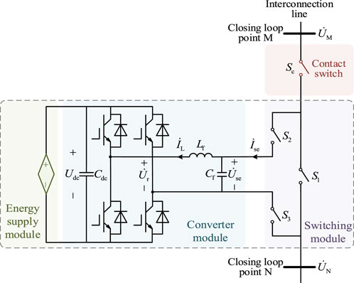
Figure 1. FID main circuit single-phase topology.
For the existing back-to-back or multi-terminal FID flexible interconnection scheme requires more full-rated power three-phase voltage source converter shortcomings, this paper proposes the FID to make full use of the existing distribution network loop device, the small-capacity single-phase regulator unit and the traditional mechanical contact switch for the integration of the design, the device cost is low; for the existing unified current controller type FID flexible interconnection scheme with the shunt side of the converter for the device to take energy, resulting in high cost of the device to take energy. In view of the shortcomings of the existing unified current controller type FID flexible interconnection scheme, which uses the shunt side converter to fetch energy for the device, resulting in the high cost of fetching energy for the device, the FID proposed in this paper is connected in parallel on the DC side with DC voltage sources such as inexpensive and many times charging and discharging energy storage batteries, supercapacitors, etc., to reduce the cost of the device, and at the same time, it can also provide the active power support for the FID before the FID flexible loop closing.
In Figure 1,
The switch module consists of a bypass switch
The converter module is composed of three single-phase full-bridge voltage source converters and filter circuits. Its main function is to output an output voltage
3 The working principle of flexible interconnection device regulation
3.1 The working principle of flexible closing loop of flexible interconnection device
In this paper, the scheme of FID and contact switch in series based on single-phase control unit is used to flexibly interconnect the low-voltage station area of distribution network. The schematic diagram of FID flexible interconnection of low-voltage AC bus in the station area is shown in Figure 2.
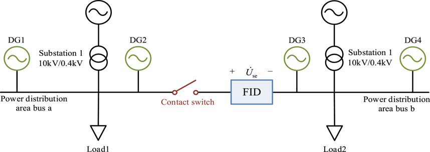
Figure 2. FID schematic diagram of flexible interconnection of low voltage AC bus in station area.
In Figure 2, FID is installed in the interconnection line between the closing point M and the closing point N in the station area. The three single-phase control units of FID can output voltage
The equivalent circuit diagram of the traditional mechanical contact switch is shown in Figure 3. Among them,
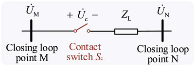
Figure 3. Traditional mechanical contact switch closing loop equivalent circuit diagram.
It can be seen from Figure 3 that when the traditional mechanical contact switch is closed, the relationship between the voltage
It can be seen from Equation 1 that there is a voltage difference between the two connecting points. If the loop is closed by directly closing the contact switch, the loop closing impulse current will be generated. Excessive loop closing impulse current may lead to line protection action, which seriously affects the success rate of loop closing and the safe and stable operation of the distribution network system. If it is necessary to improve the success rate of loop closing and suppress the inrush current in the process of loop closing, the loop closing operation specification of the phase angle difference between the two sides of the loop closing point is within 20° and the voltage difference is within 20% should be met. The key is how to control the voltage
By controlling the output voltage
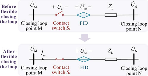
Figure 4. FID equivalent circuit diagram before and after the flexible loop closing of the station area.
From Figure 4, it can be seen that before the contact switch is closed, the line between the closing point M and the closing point N is not connected, and no current flows in the interconnecting line MN, so the line impedance voltage drop is 0. The FID control output voltage compensates for the difference in voltage at the closing point, and the voltage across the contact switch is thus obtained as
After the contact switch
In order to facilitate the analysis of the relationship between the electrical quantities in FID, the phasor
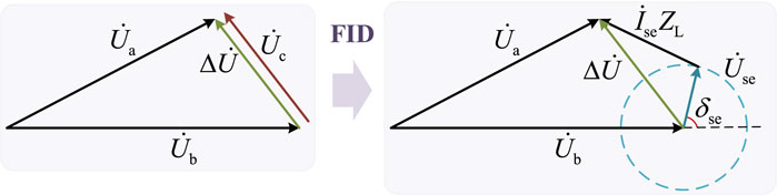
Figure 5. FID phase relationship diagram.
From Equations 1–3 and Figure 5, it can be seen that under the condition of ignoring the switching loss, by controlling the output voltage
Due to the use of single-phase full-bridge voltage source converter, FID based on single-phase control unit needs to sacrifice a control degree of freedom to maintain the active power balance of the device. In order to realize the full-angle control of the voltage difference amplitude and phase angle of the FID connection point, additional power supply modules need to be connected in parallel on the DC side to provide active power support.Therefore, FID needs to balance the active power transmission between the single-phase control unit and the energy supply module. From Figure 5 and Equation 4, it can be obtained that the active power required by FID for flexible loop closing is
When FID compensates the pressure difference for flexible closing, if the operating loss is ignored, the active power
When the FID completes the flexible closing loop to reach the steady-state operation state, the FID exits the power supply module and controls the stable DC capacitor voltage by self-powering.If there are control requirements in the station area, FID can further complete power flow control, three-phase imbalance control, harmonic suppression and other control functions according to the control instructions. If there is no need for subsequent regulation in the station area, the FID bypass will be withdrawn from operation while maintaining the interconnection of the station area, so as to reduce the line loss of the distribution network and prolong the service life of the FID.
3.2 Working principle of power flow control of flexible interconnection device
When FID is running in the steady state of the interconnected line, the equivalent impedance of the line can be changed by controlling the output voltage
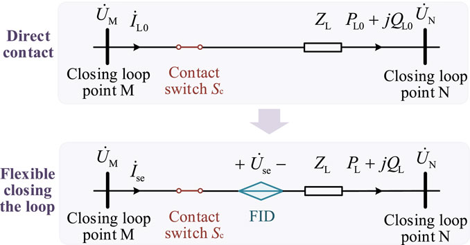
Figure 6. The steady-state operation equivalent circuit diagram of the interconnected line of direct closed loop and FID flexible closed loop is shown.
Define
The output voltage
If it is stipulated that the junction points M and N of the station area are the head and end of the interconnected line respectively, the current
The active power flow
When the FID and the series connection switch cooperate to complete the flexible closing loop, the current
After the flexible loop closing, the active power flow
It can be seen from Equation 10 that when FID controls the power flow of the interconnected line, the equivalent impedance of the interconnection device under the target value of the power flow can be calculated according to the FID output voltage and the line current, that is, by changing the amplitude and phase angle of the overall external equivalent impedance
4 Control strategy of flexible interconnection device
When FID performs flexible loop closing and power flow control in the station area, its compensation station interval differential pressure and power flow control functions are realized by controlling the output voltage
4.1 System level control strategy
In order to realize the above control functions, the interconnection operation of FID in series with the contact switch is divided into the following four stages: (1) device start-up stage; (2) Flexible closing loop stage; (3) power flow regulation stage; (4) The device out of operation stage. The following will be combined with the FID interconnection operation process and device action state diagram shown in Figure 7 to analyze these four operation stages.
Stage I: Device start-up.FID carries out real-time monitoring of the data such as the voltage of the junction point and the line current in the station area.When receiving the loop closing instruction of the station area, FID starts the power supply module to charge the DC side capacitor, and controls the converter to output the compensation voltage of the station area according to type (3).
Stage II: Flexible closing loop.The closed loop switches
Phase III: Power flow regulation.After the flexible loop is closed, if the power flow control instruction is received, the FID control converter adjusts the output voltage
Stage IV: Device out of operation.After the flexible closing stage is completed, if there is no subsequent regulation demand, the bypass switch
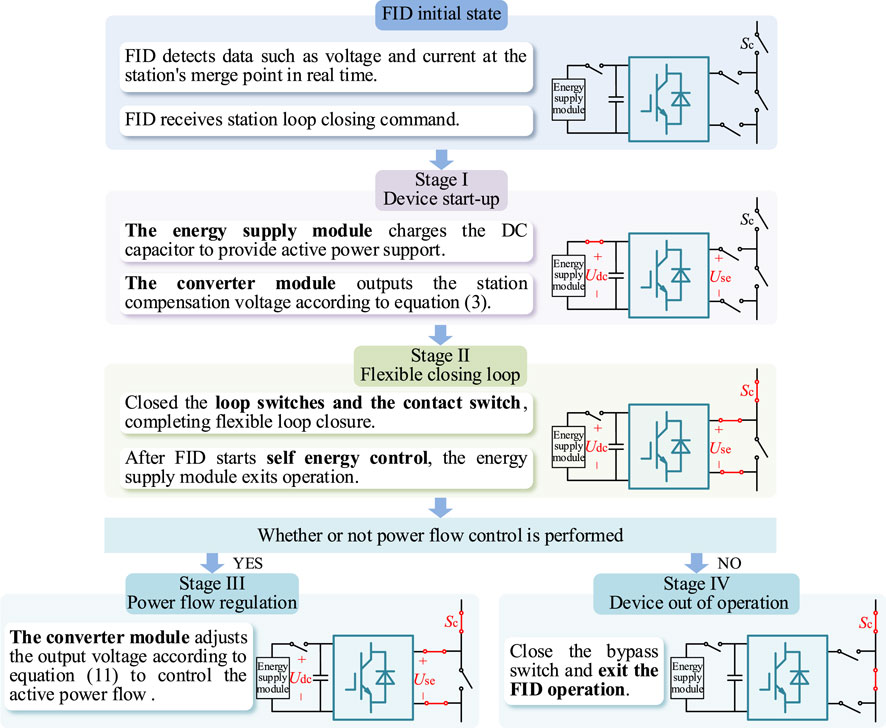
Figure 7. FID interconnection operation process and device action state diagram.
Based on the above analysis, according to the FID power balance characteristics and control function requirements, the system-level control strategy is divided into energy control strategy, flexible closed loop control strategy and power flow control strategy. The following will study the above three control strategies respectively.
4.1.1 Energy extraction control strategy
The actual value of the DC voltage output by the power supply module is
where
The instruction values of the d-axis component
where
4.1.2 Flexible closing loop control strategy
According to the Equation 3, the pressure difference
where
4.1.3 Power flow control strategy
In addition to the flexible loop closing function, FID can also carry out line power flow regulation to alleviate the problem of power flow reversal in distribution network caused by the large generation of distributed power sources such as wind power and photovoltaic, or realize the secondary distribution of power between adjacent stations through cross-station mutual assistance, so as to improve the utilization rate of system reserve capacity.Since FID needs to achieve DC voltage stability by self-energy in the power flow control stage, there is only one control degree of freedom for regulating the line power flow. Therefore, the active power
where
4.2 Device level control strategy
By controlling the output voltage, FID can perform flexible loop closing or power flow regulation, so its compensation for the differential pressure difference of the station area and the regulation of the line power flow can be transformed into the control of the d-axis component
Taking the current
where
The instruction value of the output voltage
where
Based on the above analysis, it can be seen that the output of the system-level control is used as the command values
Based on the above analysis, the FID system-level and device-level control strategy block diagram is shown in Figure 8.
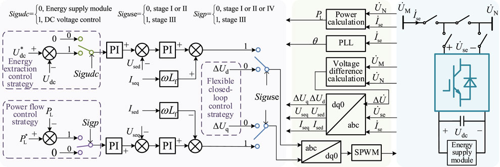
Figure 8. FID system level and device level control strategy block diagram.
5 Simulation verification
In order to verify the effectiveness of the proposed flexible loop closing and power flow control strategy of the FID series contact switch in the low-voltage area of the distribution network, the simulation model shown in Figure 2 is constructed in PSCAD/EMTDC software.The main parameters of the simulation model are set as shown in Table 1.
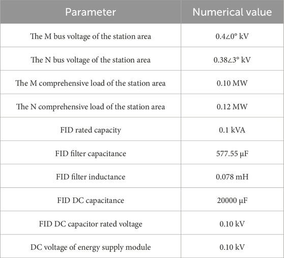
Table 1. Main parameter settings of simulation model.
The effectiveness of the proposed control strategy is analyzed by the simulation of the flexible closing loop control strategy of the FID series contact switch and the simulation of the power flow control strategy.
5.1 Simulation analysis of flexible closing loop control strategy of FID series contact switch
In order to verify the effectiveness of the flexible closing loop control strategy and the energy extraction control strategy of the FID series liaison switch, the following simulation settings are carried out: the total simulation time is 2s, the system is initialized before 0.2s, the FID device is started during 0.2–0.4s, the energy supply module charges the DC side capacitor, and the FID controls the converter to output the station area compensation voltage. At 0.4 s, the closed loop switch and the contact switch are closed, so that the FID is connected in series between the station area M and the station area N to complete the flexible loop closing. At 0.4 s, the FID starts the self-energy control. At 0.6 s, the energy supply module exits, and the FID begins to run on its own.
The FID output voltage and the pressure difference waveform of the closing point are shown in Figure 9. FID does not start before 0.2 s, and its output voltage is 0. The pressure difference amplitude of the two closing points before 0.4 s is about 0.078 kV. During 0.2–0.4 s, FID tracks the pressure difference of the station area to output the corresponding compensation voltage. It can be seen from Figure 9 that the FID output voltage tracks the pressure difference of the station area well. After 0.4 s, FID is connected to the station area through a closed loop switch to complete the flexible loop.
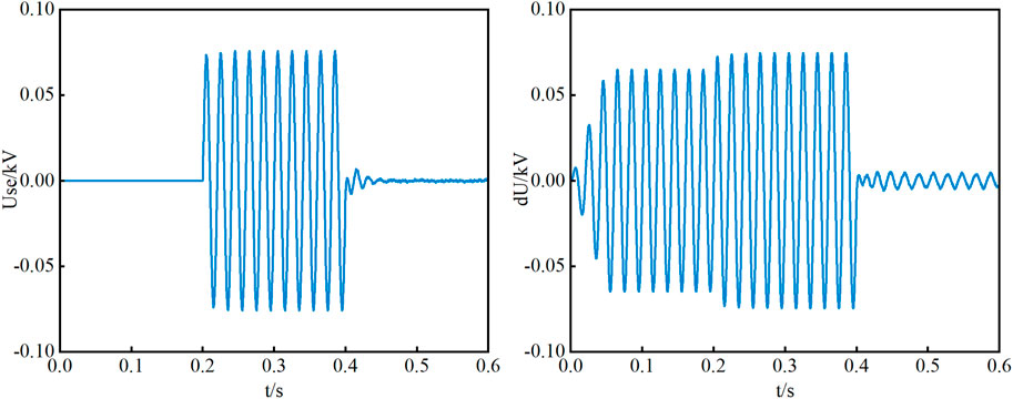
Figure 9. FID output voltage and pressure difference waveform of closing point.
The voltage waveforms at both ends of the contact switch under the flexible closing loop and the direct closing loop are shown in Figure 10. During 0.2–0.4 s, FID is not connected in series to the closing point of the station area, but the compensation voltage is output under the active support of the energy supply module. Under the action of FID compensation voltage, the voltage amplitude at both ends of the contact switch is reduced to 0.002 kV. The 0.4 s access switch is closed, and the interconnected line only needs to withstand a voltage shock with an amplitude of about 0.002 kV after compensating the differential pressure of the closing link point by FID.For the direct interconnection of the two areas, the closed-loop switch needs to bear a voltage shock with an amplitude of 0.078 kV.
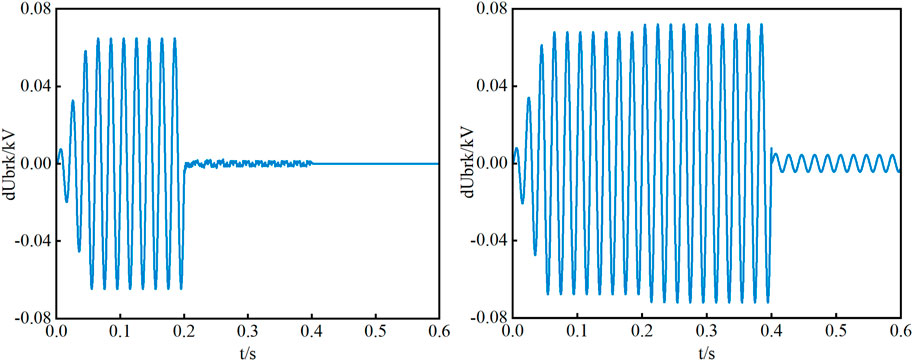
Figure 10. Voltage waveforms at both ends of the contact switch under flexible closing loop and direct closing loop.
The DC-side capacitor voltage of the FID is shown in Figure 11. The energy supply module provides a stable DC voltage for the FID during the 0–0.6 s period. The FID starts the self-powered control strategy at 0.4 s. After 0.6 s, the energy supply module exits, and the FID stabilizes the DC voltage at the command value of 0.10 kV by self-powered. When the exit of the energy supply module is delayed by the FID strategy, the DC capacitor voltage can withstand the impact of the switching between the energy supply module and the self-starting control, and always maintain the voltage stability. The output voltage can also be effectively controlled according to the command value.When the delay strategy is not adopted, that is, FID starts self-powering and the energy supply module withdraws from operation, the DC voltage oscillates at this time. If there is a subsequent demand for power flow regulation, the problem of DC voltage instability may occur.
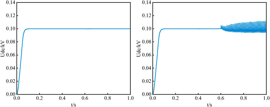
Figure 11. The FID DC side capacitor voltage waveform under the energy extraction strategy and the non-energy extraction strategy.
Based on the above analysis, FID can effectively track the pressure difference of the closing point in the station area and complete the voltage compensation. Compared with direct interconnection, FID can compensate about 97.44% of the pressure difference of the closing point. The delayed exit of the energy supply module can successfully maintain the stability of the DC capacitor voltage and ensure the stable operation of the FID.
5.2 FID power flow control strategy simulation analysis
In order to verify the effectiveness of the FID power flow control strategy, the following simulation settings are carried out: the total simulation time is 2 s, the system is initialized before 0.2 s, the FID device is started during 0.2–0.4 s, the FID is connected in series with the station area M and the station area N to complete the flexible closing loop at 0.4 s, the FID is self-powered after 0.6 s, and the active power flow of the FID control station area N rises to the command value of 0.15 MW at 1.0 s.
The active power flow and reactive power flow waveforms of the station area N are shown in Figure 12. During 0.4–1.0 s, FID is connected in series between the station area M and the station area N to complete the flexible closing loop, and the active power of the station area N is 0.05 MW.After 1.0 s, FID began to control the power flow, and the N active power flow in the station area increased from 0.09 MW to 0.15 MW.At 1.5 s, due to the disturbance of the load in the station area N, the active power of the station area N fluctuates by 0.03 s and quickly restores the 0.09 MW command value operation. The N reactive power in the station area decreases from 0.095 MVar to 0.072 MVar after 1.0 s.
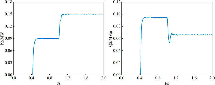
Figure 12. The waveform of N active power flow and reactive power flow in the station area.
The FID output voltage and output current waveforms are shown in Figure 13. During 0.2–0.4 s, the FID device starts the output compensation voltage, and after 0.4 s, the series connection is connected to the flexible loop between the station areas, and the output voltage is consistent with Figure 8. During 0.4–1.0 s, FID only controls the DC voltage, and its output voltage is close to 0.After 1.0 s, the FID output voltage increases to regulate the N active power flow in the station area.
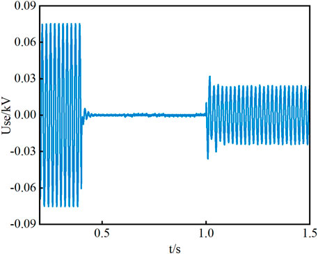
Figure 13. FID output voltage waveform.
The capacitor voltage waveform of FID DC side is shown in Figure 14. During 0–0.6 s, the energy supply module provides a stable DC voltage for FID. After 0.6 s, FID stabilizes the DC voltage at the command value of 0.10 kV by self-energy.At 1.0 s, FID controls the active power of the station area N by controlling the output voltage, and the FID DC voltage fluctuates but stabilizes near the command value of 0.10 kV.

Figure 14. FID DC side capacitor voltage waveform.
Based on the above analysis, FID can adjust the active power of the line in the station area by adjusting the output voltage of the converter, and can effectively maintain the active power of the line running at the command value, which shows the effectiveness of the FID power flow control strategy proposed in this paper.
6 Conclusion
In this paper, FID based on single-phase control unit and contact switch in series is proposed as the AC flexible interconnection scheme of low-voltage distribution network. The interconnection equivalent circuit of FID and contact switch in series is constructed. The working principle of FID flexible closing loop and power flow control is studied from the dimension of FID output voltage and equivalent impedance. The control strategies of FID energy extraction, flexible closing loop and power flow control are proposed. Finally, the proposed control strategy is simulated and verified in PSCAD/EMTDC. The following conclusions are obtained:
(1) The FID energy extraction control strategy proposed in this paper, after the successful closing of the FID, in order to prolong the service life of the energy supply module, by controlling the delayed exit of the energy supply module, the FID is switched from the energy supply module to the self-energy extraction control. The process successfully maintains the stability of the DC capacitor voltage and ensures the stable operation of the FID. Compared with the direct switching method, the extracted energy control strategy can reach the DC voltage command value within 0.01 s.
(2) The FID system-level and device-level control strategies with flexible loop closing and power flow control functions proposed in this paper can effectively track the pressure difference of the closing point and complete the voltage compensation. Compared with the direct interconnection, FID can compensate about 97.44% of the pressure difference of the closing point.In the process of power flow control, FID can adjust the output voltage of the converter to realize the effective regulation of the active power of the line in the station area, so that the active power of the controlled line can be maintained at the command value.
Data availability statement
The original contributions presented in the study are included in the article/supplementary material, further inquiries can be directed to the corresponding author.
Author contributions
YL: Conceptualization, Writing–original draft, Writing–review and editing. CD: Investigation, Writing–original draft, Writing–review and editing. XN: Methodology, Writing–original draft, Writing–review and editing. PQ: Data curation, Writing–original draft, Writing–review and editing. YS: Methodology, Writing–original draft, Writing–review and editing. ZW: Methodology, Writing–original draft, Writing–review and editing.
Funding
The author(s) declare that financial support was received for the research, authorship, and/or publication of this article. This research was funded by the Technology Project of State Grid Zhejiang Electric Power Research Institute. Technology projects grant number [5211DS24000N].
Acknowledgments
This article is grateful to State Grid Zhejiang Electric Power Research Institute Project for funding.
Conflict of interest
The research was conducted in the absence of any commercial or financial relationships that could be construed as a potential conflict of interest.
Publisher’s note
All claims expressed in this article are solely those of the authors and do not necessarily represent those of their affiliated organizations, or those of the publisher, the editors and the reviewers. Any product that may be evaluated in this article, or claim that may be made by its manufacturer, is not guaranteed or endorsed by the publisher.
References
Alwash, S., Ibrahim, S., and Abed, A. (2023). Distribution system reconfiguration with soft open point for power loss reduction in distribution systems based on hybrid water cycle algorithm. Energies 16, 199. doi:10.3390/en16010199
Cai, H., Yuan, X., Zhong, J., Zheng, H., Xu, Y., Cai, Y., et al. (2022). Flexible interconnected distribution network with embedded DC system and its dynamic reconfiguration. Energies 15, 5589. doi:10.3390/en15155589
Deakin, M., Sarantakos, I., Greenwood, D. M., Bialek, J., Taylor, P. C., Ming, W., et al. (2022). Hybrid open points: an efficient tool for increasing network capacity in distribution systems. IEEE Trans. Power Deliv. 37 (2), 1340–1343. doi:10.1109/tpwrd.2021.3136772
Fuad, K. S., Hafezi, H., Kauhaniemi, K., and Laaksonen, H. (2020). Soft open point in distribution networks. IEEE Access 8, 210550–210565. doi:10.1109/access.2020.3039552
Gui, Y., Nainar, K., Bendtsen, J. D., Diewald, N., Iov, F., Yang, Y., et al. (2024). Voltage support with PV inverters in low-voltage distribution networks: an overview. IEEE J. Emerg. Sel. Top. Power Electron. 12 (2), 1503–1522. doi:10.1109/jestpe.2023.3280926
Kabirifar, M., Fotuhi-Firuzabad, M., Moeini-Aghtaie, M., Pourghaderi, N., and Dehghanian, P. (2021). A bi-level framework for expansion planning in active power distribution networks. IEEE Trans. Power Syst. 37 (4), 2639–2654. doi:10.1109/tpwrs.2021.3130339
Kumar, N. (2024). EV charging adapter to operate with isolated pillar top solar panels in remote locations. IEEE Trans. Energy Convers. 39 (1), 29–36. doi:10.1109/tec.2023.3298817
Kumar, N., Saxena, V., Singh, B., and Panigrahi, B. (2020). Intuitive control technique for grid connected partially shaded solar PV-based distributed generating system. IET Renew. Power Gener. 14, 600–607. doi:10.1049/iet-rpg.2018.6034
Kumar, N., Saxena, V., Singh, B., and Panigrahi, B. K. (2023b). Power quality improved grid-interfaced PV-assisted onboard EV charging infrastructure for smart households consumers. IEEE Trans. Consumer Electron. 69 (4), 1091–1100. doi:10.1109/tce.2023.3296480
Kumar, N., Singh, H. K., and Niwareeba, R. (2023a). Adaptive control technique for portable solar powered EV charging adapter to operate in remote location. IEEE Open J. Circuits Syst. 4, 115–125. doi:10.1109/ojcas.2023.3247573
Li, Y., Chen, X., Li, W., Yu, S., Xu, S., Wei, T., et al. (2022). Research on interconnection structure and control technology of flexible distribution network based on soft open point in parallel with interconnection switch. Proc. CSEE 42 (13), 4749–4760. doi:10.13334/j.0258-8013.pcsee.210479
Liang, X., Saaklayen, M. A., Igder, M. A., Shawon, S. M. R. H., Faried, S. O., and Janbakhsh, M. (2022). Planning and service restoration through microgrid formation and soft open points for distribution network modernization: a review. IEEE Trans. Industry Appl. 58 (02), 1843–1857. doi:10.1109/tia.2022.3146103
Ouyang, S., Liu, J., Yang, Y., Chen, X., Song, S., and Wu, H. (2020). DC voltage control strategy of three-terminal medium-voltage power electronic transformer-based soft normally open points. IEEE Trans. Industrial Electron. 67 (5), 3684–3695. doi:10.1109/tie.2019.2922915
Qi, Y., Li, Y., Li, W., Deng, H., and Tang, Y. (2023). Autonomous control of soft open point for distribution network reliability enhancement. IEEE J. Emerg. Sel. Top. Power Electron. 11 (3), 3127–3137. doi:10.1109/jestpe.2023.3253480
Satapathy, S., and Kumar, N. (2020). Framework of maximum power point tracking for solar PV panel using WSPS technique. IET Renew. Power Gener. 14, 1668–1676. doi:10.1049/iet-rpg.2019.1132
Tang, A., Ma, L., Qiu, P., Jingen, S., Qian, C., Minyuan, G., et al. (2022a). Research on the harmonic currents rates for the exchanged energy of unified distributed power flow controller. IET Generation, Transm. and Distribution 17 (3), 530–538. doi:10.1049/gtd2.12741
Tang, A., Song, X., Shang, Y., Guo, G., Yu, M., and Zhan, X. (2024). Harmonic mitigation method and control strategy of offshore wind power system based on distributed power flow controller. Automation Electr. Power Syst. 48 (02), 20–28. doi:10.7500/AEPS20230113008
Tang, A., Yang, Y., Yang, H., Song, J., Qiu, P., Chen, Q., et al. (2023). Research on topology and control method of uninterrupted ice melting device based on non-contact coupling power flow controller. Proc. CSEE 43 (22), 8666–8674. doi:10.13334/j.0258-8013.pcsee.220221
Tang, A., Zhou, W., Song, J., Qiu, P., Chen, Q., Zhai, X., et al. (2022b). Optimal output power coordinated control strategy of distributed power flow controller. Int. J. Electr. Power Energy Syst. 140, 108075. doi:10.1016/j.ijepes.2022.108075
Wu, T., Zheng, Y., Wu, H., Dong, H., and Wang, X. (2019). Power transfer and multi-control mode of a distribution network based on a flexible interconnected device. IEEE Access 7, 148326–148335. doi:10.1109/access.2019.2946710
Xu, Y., Liu, H., Xiong, X., Ji, Y., Shao, Y., Zhang, H., et al. (2022). Key technologies and development modes of flexible interconnection of low-voltage distribution station area. Proc. CSEE 42 (11), 3986–4001. doi:10.13334/j.0258-8013.pcsee.210578
Zhang, J., Feng, X., Zhou, J., Zang, J., Wang, J., Shi, G., et al. (2023). Series–shunt multiport soft normally open points. IEEE Trans. Industrial Electron. 70 (11), 10811–10821. doi:10.1109/tie.2022.3229375
Keywords: single-phase control unit, interconnection switch, flexible interconnected device, flexible closing loop, power flow control
Citation: Lu Y, Ding C, Ni X, Qiu P, Shang Y and Wang Z (2025) Research on topology and control strategy of distribution network flexible interconnected device based on single-phase control unit and contact switch in series. Front. Energy Res. 13:1464371. doi: 10.3389/fenrg.2025.1464371
Received: 14 July 2024; Accepted: 10 February 2025;
Published: 28 February 2025.
Edited by:
Shuqing Zhang, Tsinghua University, ChinaReviewed by:
Qianzhi Zhang, Cornell University, United StatesYosi Apriani, Universitas Muhammadiyah Palembang, Indonesia
Copyright © 2025 Lu, Ding, Ni, Qiu, Shang and Wang. This is an open-access article distributed under the terms of the Creative Commons Attribution License (CC BY). The use, distribution or reproduction in other forums is permitted, provided the original author(s) and the copyright owner(s) are credited and that the original publication in this journal is cited, in accordance with accepted academic practice. No use, distribution or reproduction is permitted which does not comply with these terms.
*Correspondence: Zihan Wang, MTUwNTE2MzU3N0BxcS5jb20=