 Qian Feng1
 Jiaxin Zuo
- 1State Grid Shanghai Electric Power Research Institute, Shanghai, China
- 2College of Electrical Engineering, Shanghai University of Electric Power, Shanghai, China
The large-scale grid connection of new energy sources makes the power system highly electronic. The resulting broadband oscillation problem is the main challenge hindering the safe and stable operation of current high-proportion new energy power systems. To ensure the safe operation of the power grid, it is important to carry out systematic research on broadband oscillation suppression measures. At present, an additional damping controller method is often used in broadband oscillation suppression, but the parameter optimization problem for the additional controller of new energy units and flexible DC transmission systems must still be further explored. This article first establishes a state–space model of direct-drive permanent magnet wind farms connected to the AC and DC grid systems and uses eigenvalue analysis to analyze the broadband oscillation modes involved. Then, additional damping controllers are designed for wind turbines and flexible DC transmission systems, and a parameter optimization model is established with the maximum damping ratio of the coupled oscillation mode as the optimization goal. The Improved Plant Growth Simulation algorithm (I-PGSA), based on cloud model theory with good global search and a fast calculation speed, is used to optimize and solve the additional damping controller parameters. In addition, considering that adjusting the controller parameters during the optimization process may cause the target mode frequency to change too much, so it is impossible to continue to optimize it, this article further introduces mode tracking technology to track the target mode to ensure that no target offset occurs during the optimization process. Finally, through eigenvalue analysis and power systems computer-aided design/electromagnetic transients, including DC (PSCAD/EMTDC) time domain emulation, the system is compared before and after governance, and it is verified that the proposed controller parameter optimization strategy can effectively suppress the system broadband oscillation problem.
1 Introduction
In recent years, in the face of the depletion of traditional energy sources, climate warming, and other problems, the Chinese government has proposed to improve energy structure and fully promote the development of clean energy. Wind energy has the advantages of being clean and pollution-free with large reserves and is an extremely important component of new energy. With the continuous expansion of wind power grid-connected capacity, flexible DC transmission is widely used in long-distance and large-capacity wind power transmission problems, with its advantages of small transmission loss, independent control of active and reactive power, and no phase change failure (Wang et al., 2014). At the same time, wind farm power consumption in closer cities often uses AC transmission. Therefore, the wind farm power transmission processes will often form a mixed AC and DC grid structure. However, the large number of power electronic components brought by wind power grid integration to the source and network sides of the grid will cause wide-frequency oscillation problems, which will affect the safe and stable operation of the grid.
Since the beginning of the 21st century, wide-frequency oscillation problems have occurred frequently in global wind power grid-connected projects: in 2009, a wide-frequency oscillation problem of approximately 22 Hz occurred in a wind farm in Texas, United States, due to an excessively high fault-induced string complement (Xing et al., 2020). In 2015, a multi-band wide-frequency oscillation phenomenon of 20–90 Hz occurred in the direct-driven wind farm of the Hami region, Xinjiang, in a trans-ac transmission project, which caused a protection shutdown of a nearby thermal power unit (Jiang and Wang, 2020; Ma et al., 2020). In addition, wide-frequency oscillations of wind farms via flexible direct or AC feeder systems have also occurred in Guangdong, Shanghai, Fujian, and other places (Wei et al., 2015; Zhao et al., 2012).
These accidents have made scholars pay more attention to the wide-frequency oscillation caused by wind farms and power electronic equipment brought into the grid by flexible transmission. Many studies have been conducted on the above problems both within China and in other countries, but they mostly focus on a single transmission mode. For example, Zhang et al. (2014) only considered the wind turbine alone through the AC and DC when designing the damping controller, and the coupled oscillation mode between the AC and DC systems was not studied. Yang et al. (2020) established a research model for the series compensation system of doubly fed wind turbines and analyzed the new type of sub-synchronous resonance problem caused by the integration of power electronic equipment. Gao et al. (2020) established a small signal model for the line-commutated, converter-based high-voltage direct current (LCC-HVDC) transmission system of a doubly fed wind farm and analyzed the sub-synchronous oscillation characteristics of the system through eigenvalue analysis and participation factor analysis. Sun et al. (2018) established a system equivalent model for doubly fed wind farms to directly enter the AC power grid via flexible input and studied the sub-synchronous oscillation characteristics of the system based on the impedance stability analysis method. Bian et al. (2018) studied the sub-synchronous oscillation mechanism between offshore doubly fed wind farms and flexible DC transmission systems and proposed oscillation suppression measures based on additional damping controllers using signal testing methods. Wang et al. (2020) studied the problem of sub-synchronous oscillation in the grid-connected system of direct-drive wind turbines using the impedance analysis method.
The above literature models wind farms as an equivalent wind turbine connected to the power grid but does not consider the impact of system structural parameters on coupled oscillations during the research process. Lyu and Cai (2015) established a small signal impedance analysis model for three-phase MMC on the AC side of a modular multilevel converter-based high-voltage DC (MMC-HVDC) grid-connected system for offshore wind farms. The frequency domain analysis method was used to study the influence of controller parameters on system stability. Lyu et al. (2016) further considered circulating current control in the impedance model of MMC (Lyu et al. (2017). Lyu et al. (2018) established a small signal impedance model of MMC based on the harmonic state–space modeling method and studied the phenomenon of sub-synchronous oscillation in the system. Amin et al. (2015) and Amin and Molinas (2017) proposed an active damping scheme that can increase the stability of wind turbines connected to a flexible DC transmission grid system.
The above literature examined the situation where wind farms are connected to the power grid separately through flexible DC or AC but did not consider the interactive effects between wind farms and AC/DC transmission modes under different connection methods. In summary, the current research on the parallel operation of different types of wind turbines in different transmission modes (e.g., AC and DC) is still insufficient, and the research on the interaction between AC and DC and the structural parameters of the system also must be in-depth.
In this article, we first construct a state–space model of multiple wind turbines connected to the power grid through AC and DC. The root-of-feature method is used to analyze the mechanism of the oscillatory modes that can easily destabilize the system and to determine the key factors that are affected. Then, an additional damping controller is designed for the corresponding oscillation modes. The parameters of the additional damping controller are used as the optimization variables, and the coupled oscillation modes are used as the improvement targets. The overall optimization model of the controller parameters is constructed by raising the damping ratio of the coupled oscillation modes over a certain threshold to achieve the optimization target of not affecting the stability of the system as much as possible. To keep the target from shifting during the optimization process of the algorithm, the mode tracking technique is introduced at the same time, and the I-PGSA is used to solve the model and calculate the optimal additional controller parameters. Finally, the optimization effect of control parameters is verified and compared by eigenvalue analysis and simulation.
2 Wind farm AC/DC grid-connected system modeling
Figure 1 shows the system structure of the wind farm connected to the grid via AC and DC, including the DC part and the AC part. According to the literature (Gao et al., 2018), the single-machine and multi-machine wind farm models show a high degree of similarity in the oscillation law. Therefore, in this article, the direct-drive permanent magnet synchronous generator (D-PMSG) aggregation model is used to simulate the whole wind farm. In the overall system, the permanent magnet direct-drive wind farm is connected to the flexible system through AC lines and transformers, and, finally, the power is delivered to the recipient grid.
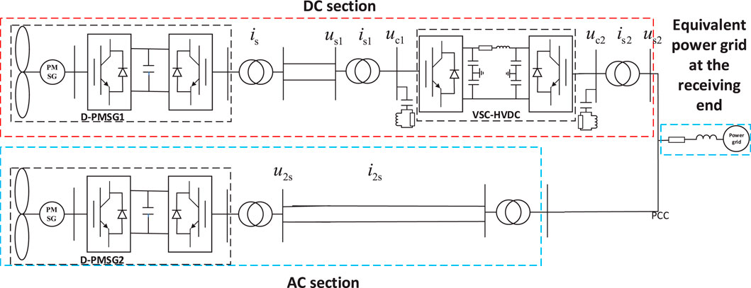
Figure 1. Structural diagram of a wind farm connected to the power grid system through AC and DC.
2.1 Dynamic model of a permanent magnet direct-drive wind turbine
The D-PMSG consists of a wind turbine shaft system, a back-to-back converter, and a DC link. A dual-mass module is used in the modeling of the permanent magnet direct-drive wind turbine to describe the mechanical characteristics of the shaft system of the D-PMSG, and the linearized model of the shaft system is as follows:
where p is the differential operation factor; subscripts a and b correspond to the wind turbine and generator, respectively; Δωa, Δωb, and TJa, TJb are the rotational speed and inertia time constant, respectively; ωr is the rotational speed reference value; Daa, Dbb, and Dab are the self-damping coefficients as well as mutual damping coefficients; Kab is the stiffness coefficient of the shaft system; ΔTa and ΔTb are the mechanical torque and electromagnetic torque, respectively; Δδa and Δδb are the electrical angular displacements of the wind turbine rotor and the generator rotor, respectively, relative to the synchronous rotating reference axis of the rated electrical speed.
The remaining parts of the dynamic model can be found in the literature (Chen et al., 2018).
2.2 Flexible dynamic modeling
The flexible model is composed of the rectifier inverter and its controller, the inverter and its controller, and the DC transmission link, and the specific structure is shown in Figure 2.
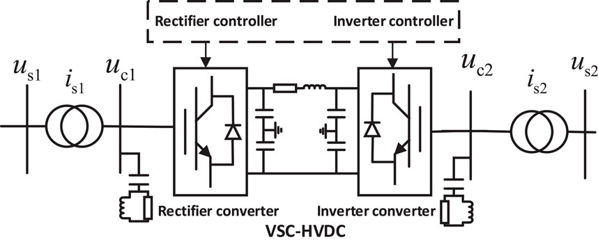
Figure 2. Flexible and straight topological structure.
The sender-side converter model and the receiver-side converter model set up the positive sequence d-q coordinate system with the grid voltage us1 and us2 as the reference, respectively. Then, the dynamic model of the voltage source converter-based high-voltage direct current transmission (VSC-HVDC) system is as follows:
where is1d and is2d are the sending end current and the receiving end current; idc is the direct current; udc1 and udc2 are the sending end DC voltage and the receiving end DC voltage; ωs1b and ωs2b are the grid angular frequencies on the AC side of the sending end and the receiving end; R1 and L1 are the equivalent resistance and inductance of the outlet transformer of the sending end converter; R2 and L2 are the equivalent resistance and inductance of the outlet transformer of the receiving end converter, respectively.
Among them, the sender end controller adopts the fixed active and fixed reactive power control strategy, and the receiver end controller adopts the fixed DC voltage and fixed reactive power control strategy.
2.3 Interface equation establishment
In building the unified state–space model, the coordinate system of each module must be unified using a coordinate transformation because the reference coordinate system of each module is different. In the grid-side converter model of D-PMSG, the d1-q1 rotational coordinate system is set based on the grid voltage us, while in the feeder converter model of VSC-HVDC, the d2-q2 rotational coordinate system is set based on the voltage us1.
The interface dynamic equations, that is, the dynamic equations of the AC transmission line, are obtained by transforming the physical quantities in the VSC-HVDC feeder converter and its controller model based on the d1-q1 rotational coordinate system to the d2-q2 rotational coordinate system:
Among them,
2.4 System-wide equation of state
The non-linear mathematical model of each module is converted into a state–space model by means of linearization as follows:
where X and Y are the system state variables and algebraic variables, respectively; A1, B1, and C1 are the state matrix, the state and algebraic variable relationship matrix, and the algebraic and state variable relationship matrix, respectively.
Using the input–output relationship between modules, that is, the above interface equations, combined with the method of coordinate transformation, the state equations of different modules are converted to a unified coordinate system to form the state–space model of the whole system.
The dynamic equation of the whole system is as follows:
where XPMSG1 and XPMSG2 are the wind turbine generators (WTG) state variables; Xplls is the phase-locked loop state variable; XPMSG1-Ctrl and XPMSG2-Ctrl are the WTG control system state variables; and XHVDC is the VSC-HVDC state variable. Δθpllsi and ΔZplli are the phase-locked loop i (i = 0, 1, 2, 3), respectively, negative state variables of the output phase and angle instantaneous change values of the controller; Δω3 and Δω4 are the electrical rotational speeds of the rotor of the PMSG1 wind turbine and generator, respectively; Δω1 and Δω2 are the electrical rotational speeds of the rotor of the PMSG2 wind turbine and generator, respectively; Δδ3 and Δδ4 are the electrical angular displacements of the rotor of the PMSG1 wind turbine and generator relative to the reference axis for synchronous rotation at rated electrical speed; Δδ1 and Δδ2 are the electrical angular displacement of PMSG2 wind turbine and generator rotor relative to the rated electrical speed synchronous rotation reference axis; Δid and Δiq are the d- and q-axis components of the grid-connected current of PMSG1, respectively; Δi2d and Δi2q are the d- and q-axis components of the grid-connected current of PMSG2, respectively; Δudc and Δu2dc are the DC voltages of PMSG1 and PMSG2, respectively; Δi2sd and Δi2sq are the d-axis and q-axis components of the PMSG2 outlet AC current, respectively; Δw4 and Δw6 are the d- and q-axis state variables of the PMSG1 machine-side current controller, respectively; Δw1 and Δw3 are the d- and q-axis state variables of the PMSG2 machine-side current controller, respectively; Δw5 is the state variable of the PMSG1 machine-side speed controller; Δw2 is the state variable of the PMSG2 machine-side speed controller; Δx4 and Δx6 are the d-axis state variables of PMSG1 grid-side voltage and the q-axis state variables of current controller, respectively; Δx1 and Δx3 are the d-axis state variables of PMSG2 grid-side voltage and the q-axis state variables of current controller, respectively; Δx5 is the d-axis state variable of the PMSG1 grid-side current controller; Δx2 is the d-axis state variable of the PMSG2 grid-side current controller; Δy1 and Δy3 are the d- and q-axis state variables of the VSC-HVDC external loop active and reactive power controller, respectively; Δy2 is the d-axis state variable of the VSC-HVDC inner loop circuit controller; Δy4 sends the d-axis state variable of the inner loop current controller at the end; Δz1 and Δz3 are the external loop voltage and reactive power controller state variables at the VSC-HVDC receiving end, respectively; and Δz2 and Δz4 are the d- and q-axis state variables of the VSC-HVDC receiver loop current controller, respectively.
3 Eigenvalue calculation and analysis
3.1 Eigenvalue calculation and participation factor analysis
The initial conditions of the system are set in Supplementary Table A1 in Supplementary Appendix A. To distinguish the intrinsic oscillation modes of the two wind turbines to avoid the resonance of the two oscillation modes with similar frequencies, the unit parameters of the two direct-driven wind turbines are slightly different. The specific parameter settings of each part are shown in Supplementary Tables A2–A6 in Supplementary Appendix A. The results of the analysis of the eigenvalues obtained under the initial conditions of the system are shown in Table 1.
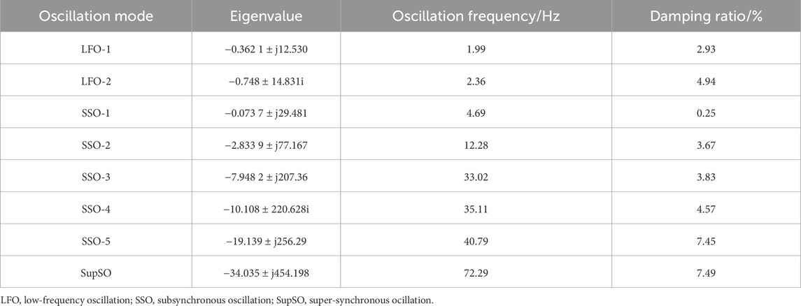
Table 1. Eigenvalue analysis results.
The damping ratio of the LFO-1 oscillatory mode is 2.93%, a value below the 3% damping ratio threshold, and the mode is weakly damped with a high risk of instability. In contrast, the damping ratio of the LFO-2 oscillation mode is 4.94%, which exceeds the damping ratio threshold, indicating that this mode is relatively stable. In the sub-synchronous frequency band, except for the SSO-1 mode with a lower damping ratio, the damping ratios of the SSO-2 to SSO-5 modes are all greater than the threshold value of 3%, thus possessing better stability. The damping ratio of the SupSO oscillation mode is 7.49%, which exceeds the threshold value of the damping ratio and, therefore, the mode has a high degree of stability.
In summary, the LFO-1 and SSO-1 modes have a greater risk of instability. Most of the remaining oscillation modes show high damping ratios and relatively stable performances. The participation factors of each oscillation mode are obtained by the eigenvalue analysis method, as shown in Table 2.
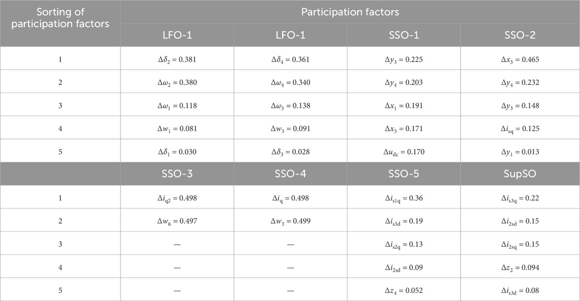
Table 2. Ranking of participation factors for each oscillation mode.
In Table 2, Δis1dq, Δis2dq, and Δi2sdq represent the communication network between D-PMSG and VSC-HVDC, the VSC-HVDC receiving end communication network, and the variables transmitted by D-PMSG through the communication network, respectively; Δis3dq is the sum of the VSC-HVDC output current and the D-PMSG AC line current; Δisq is the q-axis state variable of the AC network current component between D-PMSG and VSC-HVDC.
Analyses using Table 2 data show that
(1) The two sets of oscillation modes of LFO are caused by the shaft systems of D-PMSG1 and D-PMSG2, respectively, and the subsystems involved in the oscillations are their respective shaft systems.
(2) The SSO-3 and SSO-4 oscillation modes are caused by D-PMSG1 and D-PMSG2 themselves, which are mainly affected by the machine-side controllers of the permanent magnet direct-drive (PMD) wind turbine, and the subsystems involved in the oscillations are D-PMSG1 and D-PMSG2.
(3) The two SSO-1, SSO-2 oscillation modes are caused by the interaction between D-PMSG1 and the soft direct, and the subsystems involved in the oscillations are VSC-HVDC and the D-PMSG1 controller.
(4) The two sets of oscillation modes of the SSO-5 and SupSO are caused by the interaction between the flexible DC and the permanent magnet direct-drive feeder AC transmission line, and the subsystems involved in the oscillations are D-PMSG1 and VSC-HVDC.
3.2 Time domain simulation verification
The model shown in Figure 1 was built in the PSCAD/EMTDC environment, with a simulation duration of 10.0 s. When the system runs for 2.0 s, a single-phase ground short-circuit fault with a duration of 0.2 s is applied at the point of common coupling (PCC) of the receiving grid. The change in the active power output at the PCC is observed. The waveform of the output active power is shown in Figure 3a The output active power of the established system was analyzed using the Prony analysis method, and the results are shown in Figure 3b.
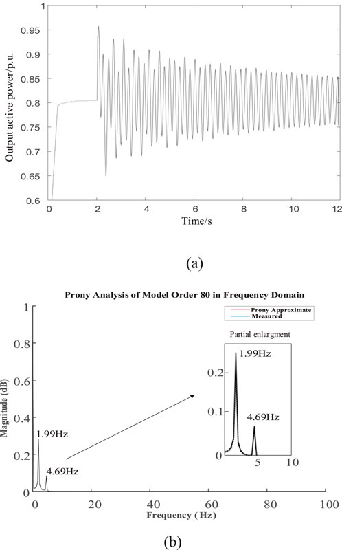
Figure 3. Active power waveform diagram and Prony analysis chart. (a) Active power oscillation waveform. (b) Prony analysis chart.
According to Figure 3, the frequency components of the output active power include sub-synchronous oscillation components at 1.99 Hz and 4.69 Hz. The amplitude of 1.99 Hz is relatively large, indicating strong oscillation. The results in Figure 3 are consistent with those in Table 2, verifying the correctness of the model established in the previous section.
4 Damping controller parameter optimization, model building, and solving
Given that the coupled oscillation mode is often influenced by multiple factors, it is difficult to adjust a controller parameter alone to achieve the effect of suppressing the oscillation, so more attention is needed for the governance of the coupled oscillation mode. Additional damping control has better results for the suppression of broadband oscillations, but when dealing with multimodal oscillation problems, the corresponding suppression links must be designed separately for the frequency characteristics of each modal oscillation, and the calculation process is more complicated. Therefore, this article further improves the suppression effect of the system’s broadband oscillations by optimizing the parameters of additional controllers on the basis of existing studies.
4.1 Damping controller design
A damping controller uses system electrical quantities (average unit speed, active power, reactive power, etc.) as the input signal. Different frequencies of the oscillating components extracted will be filtered through the bandpass filter. Then, the amplitude and the phase of this group of signals can be moved to form a signal that can offset or compensate for part of the original oscillating components of the damping to achieve the damping control.
4.1.1 Direct-drive turbine network side damping controller design
The design structure of the single-group damping controller is shown in Figure 4.
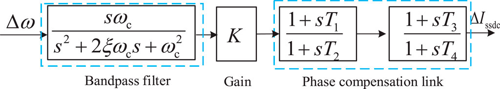
Figure 4. Design structure of a single-group damping controller.
The damping controller state equation is
where p = d/dt is the differential operator; ωc is the cut-off frequency; ξ is the damping ratio; Δω is the rotational speed deviation signal; K is the gain coefficient; X1 and X2 are the output variables of the filters, respectively; X3 and X4 are the output variables of the phase compensation link, respectively; and Ti is the time constant.
Meanwhile, the damping controller designed to be multimodal has multiple sets of bandpass filters for being multimodal. The specific structure is shown in Figure 5.
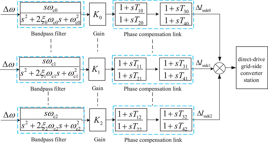
Figure 5. Additional damping control for a permanent magnet direct-drive network side controller.
4.1.2 Design of a damping controller for flexible straightening
For flex-straight, the sender end controller triggers more complex broadband oscillations, that is, SSO-1 and SSO-2. It can be governed by additional damping control of the VSC-HVDC sender end controller. The control strategy is shown in Figure 6.
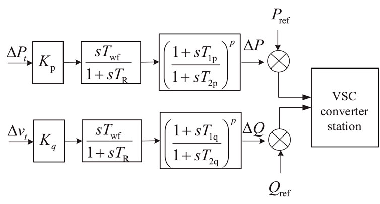
Figure 6. Flexible and straight additional damping control.
As seen in Figure 6, the additional damping control is to achieve the decoupling control of active and reactive power by adding damping controllers in the active and reactive power control loops, respectively, which helps to quickly calm the power oscillation phenomenon in the system. The parameter optimization for the additional damping of the VSC-HVDC is mainly for Kp, T1p, T2p, Kq, T1q, and T2q, and the other parameters can be set as Twf = 10; TR = 10; p = 2, respectively. In Figure 6, Kp and Kq are gain coefficients; T1p, T2p, T1q, T2q, Twf, and TR are time constants; and p is the power.
4.2 Damping controller parameter optimization model
To govern the coupled oscillation modes generated by the system with the additional damping controller, the parameter optimization model of the additional damping controller is established by taking the additional damping controller parameters as the optimization variables, setting the coupled oscillation modes as the improvement objective, and taking the damping ratio of the coupled oscillation modes as high as possible as the optimization objective.
where K is the number of target modes; η is the weight coefficient of the target mode; ξ is the damping ratio of the target mode; and F is the objective function.
(1) The damping ratio of the mode to be improved should be greater than a certain threshold. The current study shows that a damping ratio below 3% can be regarded as a low-damping mode, but considering a certain margin, this article takes 5% as the threshold.
(2) The damping ratio of the remaining oscillation modes cannot be smaller than the pre-optimization damping ratio.
(3) Each controller must satisfy its specific parameter constraints, that is, keep its proportional and integral gains within the limited constraints. Because the additional damping controller strategies are different for a permanent magnet direct drive and a flexible direct drive, the parameter values are also different. For the flexible additional damping controller, Kpmax takes the value of 300, Kimax takes the value of 1, and Kpmin and Kimin take the value of 0. For the permanent magnet direct-drive additional damping controller, Kpmax takes the value of 50, Kimax takes the value of 5, and Kpmin and Kimin take the value of 0. Then, we can get the constraints on the parameter solution model of the damping controller, as shown in the following equation:
where kp-a.b, kp-a.b-max, and kp-a.b-min are the bth proportional gain coefficients and their upper and lower limit values of the ath additional damping controller, respectively; ki-a.b, ki-a.b-max, and ki-a.b-min are the bth integral gain coefficients and their upper and lower limit values of the ath additional damping controller, respectively; ξj, λj1, and λj2 are the damping ratio, damping ratio threshold, and initial damping ratio of the target oscillation mode j, respectively; and ξk and λk are the damping ratio and damping ratio threshold of the remaining oscillation mode k, respectively.
4.3 Mode tracking
Considering that the optimization objective is to maximize the damping ratio of the target modes, additional damping controllers are applied to the grid-side controller of the permanent magnet direct-drive wind turbine and the flexible and straight receiver-end controller. When solving the parameters of the additional damping controller, adjusting the controller parameters leads to changes in the eigenvalues of the system, which may cause significant changes in the frequency of the target oscillation mode. If the frequency of the target mode changes too much, it may lead to the loss of tracking of the optimization target in the subsequent optimization iterations, and thus, the optimization of this target mode cannot be continued. For this reason, a mode tracking technique is introduced in the optimization strategy proposed in this article to ensure that the optimization process always improves on the pre-selected oscillatory modes. The target mode is tracked through the information of the first five participant orderings of the mode, the left and right eigenvectors, and the oscillation frequency to ensure that the optimization is always performed for the given target mode.
For an oscillatory pattern m, the oscillatory pattern similarity is defined by drawing on the paradigm similarity search as
where Ra and Rb are the sets of corresponding feature information (including the eigenvalues of the mode, the ordering of the participation factors, the frequency of oscillation, and the left and right eigenvectors and the angle between them) of the oscillatory mode m in the optimization process and the initial conditions, respectively; ai and bi are the ith feature information of Ra and Rb, respectively; wi and Fi are the weights and the ranges of values of the ith feature information of the oscillatory mode m, respectively; Sm is the similarity of oscillation modes.
4.4 Optimal model solution based on the I-PGSA algorithm
PGSA is an algorithm to simulate the phototropism (optimal growth) of plants, but the conventional PGSA can only be used for problems in integer programming. Therefore, the cloud model theory is incorporated into the conventional method. The cloud model, with its ability to find certainty in uncertainty and to achieve dynamic changes in stability, simulates the fundamental mechanism of plant growth in nature well and can change the accuracy of the results of each calculation, targeting the problem that can only be dealt with in integer planning. At the same time, it adopts the method of varying the step size to improve the convergence speed and to shorten the computation time. The flow of optimizing the damping controller parameters using the I-PGSA algorithm is shown in Figure 7.
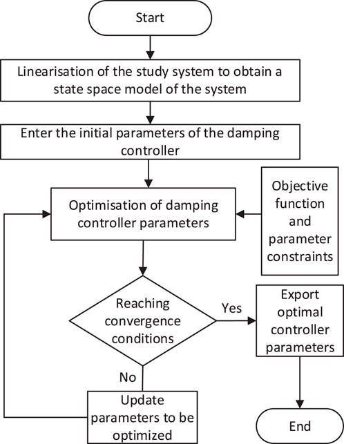
Figure 7. Damping controller parameter optimization flowchart.
5 Simulation example
5.1 Eigenvalue analysis and comparison
For SSO-1, SSO-2 (coupled oscillation mode between flexible direct and permanent magnet direct-drive wind turbines), its related controllers (grid-side converter (GSC), sending-end controller (SEC)), and additional damping controllers are governed, and its calculation results are compared with those of the undamped controller to determine the feasibility of optimization. The initial parameters of the additional damping controller are shown in Table 3. In Table 3, Ks1 and Ks2 are the gain coefficients of the GSC additional damping controller; Ts11, Ts12, Ts13, Ts14, Ts21, Ts22, Ts23, and Ts24 are the time constants of the GSC additional damping controller.
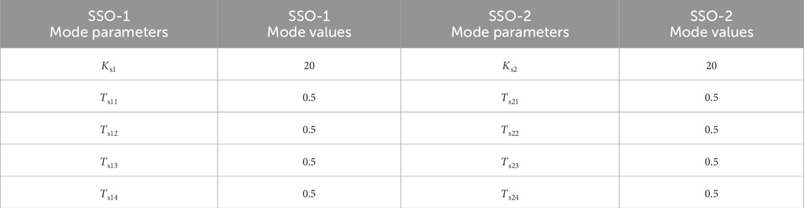
Table 3. Initial parameters of the GSC additional controller.
I-PGSA is used to solve the above controller parameters, with the maximum number of iterations being 20; the other parameters of the system remain unchanged. The final iteration results are shown in Table 4, while the eigenvalue calculations are performed under this parameter, and the results are shown in Table 5 and Figure 8.
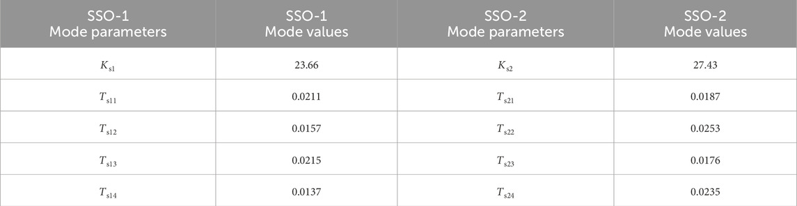
Table 4. Additional controller optimized parameters.
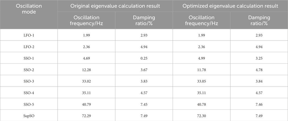
Table 5. Initial parameters of the GSC additional controller.
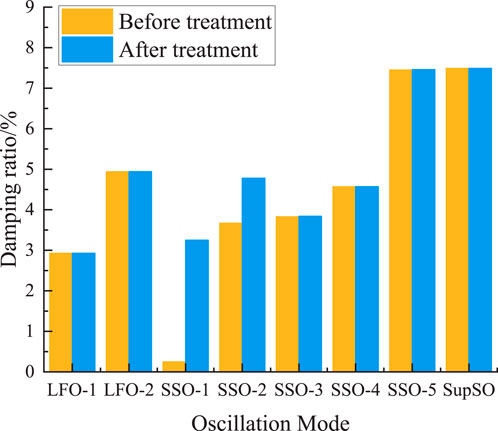
Figure 8. Comparison of the damping ratios of various oscillation modes before and after governance.
From Table 5 and Figure 8, it can be seen that, in the absence of the additional damping controller, SSO-1, SSO-2 oscillation mode damping is relatively low. With the additional damping controller parameters gained through the optimization, the SSO-1, SSO-2 oscillation mode damping ratio has a considerable increase. The impact of the remaining oscillation mode is smaller, and it is possible to accurately sort out some of the oscillation modes. Therefore, it has better feasibility.
The additional damping controller initial parameters for the SSO-5, SupSO (coupled oscillation mode between AC and DC subsystems) and its related control system’a (flexible direct receiver control system) additional damping controller for governance are shown in Table 6. The final iteration results are shown in Table 7. The eigenvalue calculations are carried out under this parameter, and the results are shown in Table 8 and Figure 9.
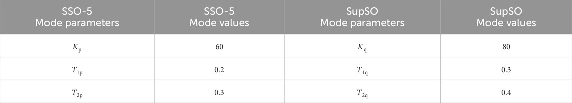
Table 6. Additional controller initial parameters.
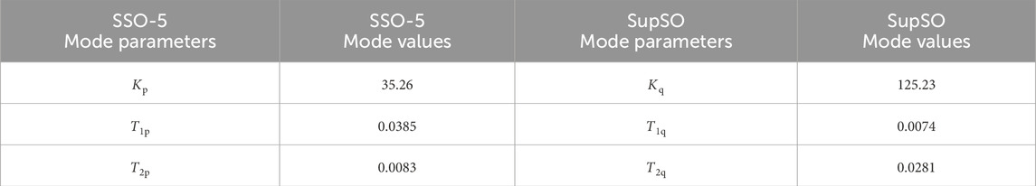
Table 7. Additional controller optimized parameters.
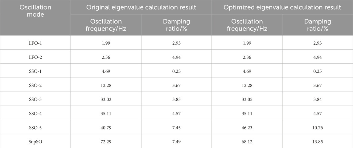
Table 8. Comparison of eigenvalues before and after adding an additional damping controller.
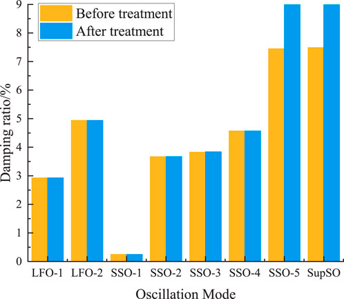
Figure 9. Comparison of damping ratios of various oscillation modes before and after governance.
As can be seen from Table 8 and Figure 9, when there is no additional damping controller, the damping ratio of the SSO-5 and SupSO oscillation modes is relatively low. After the optimization of the parameters of the additional damping controller, the damping ratio of the SSO-5 and SupSO oscillation modes has risen considerably. The impact on the rest of the oscillation modes is small, so that it is feasible to accurately sort out certain oscillation modes.
5.2 Time domain simulation verification
The model shown in Figure 1 was built in PSCAD/EMTDC software, and a damping controller was attached to the grid-side controller of the permanent magnet direct-drive wind turbine. The PCC of the grid was set at the receiving end to cause a single-phase ground short-circuit fault at 2–2.2 s. The active power output of the system was observed. The comparative analysis chart of the obtained active power is shown in Figure 10.
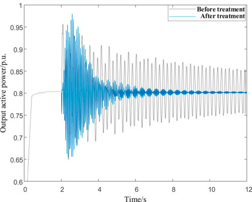
Figure 10. Comparison analysis chart of active power.
From Figure 10, it can be seen that the system is oscillating, and it is not easy to converge when a small disturbance is added before the damping controller is put into use. However, after the damping controller is put into use and the parameters are optimized, the oscillation of the system is quickly calmed after a small disturbance is added, which verifies the feasibility of the damping controller design method in this article.
The damping controller is attached to the flexible direct receiver controller, and the same simulation conditions as above are set. The resulting active power comparison analysis is shown in Figure 10.
From Figure 11, it can be seen that after the damping controller is put into operation and the parameters are optimized, adding small disturbances does not flatten the oscillation of the system. Considering that the damping ratios of the coupled oscillation modes related to the receiving end of the VSC-HVDC are affected by various factors, adjusting only the parameters of the VSC-HVDC controller may improve a single oscillation mode, but it may also deteriorate other oscillation modes, thus obtaining the simulation results. However, the previous verification showed that adjusting the parameters of the additional damping controller can effectively improve both sets of coupled oscillation modes simultaneously. It also proved that the damping controller design method proposed in this article has excellent governance capabilities for coupled oscillation modes.
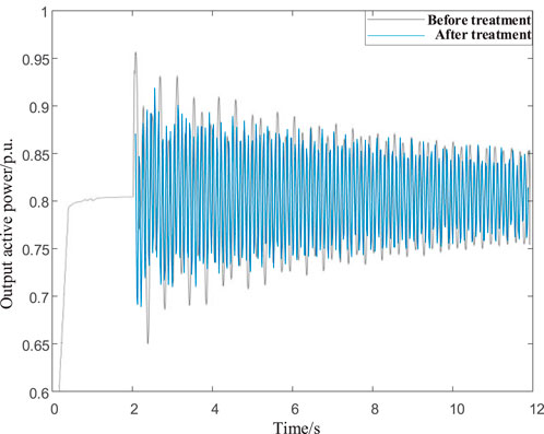
Figure 11. Comparison analysis chart of active power.
6 Conclusion
In this article, the state–space model of a wind farm with AC/DC access to a grid system is established, and the mechanism analysis of the oscillatory modes, which are more likely to destabilize the system, is carried out by using the eigenroot method to determine the key factors affected by it. Then, an additional damping controller is designed, and its parameters are used as the optimization variables. The coupled oscillation mode is used as the improvement objective to achieve a faster optimization model solution through the I-PGSA algorithm. To keep the objective from shifting during the optimization process of the algorithm, a mode tracking technique is also introduced to track the target mode. Finally, the control parameter optimization effect is verified and compared by eigenvalue analysis and time domain simulation. The conclusion is as follows:
(1) When governing the oscillation modes of SSO-1 and SSO-2, the optimized additional controller parameters Ks1, Ts11, Ts12, Ts13, and Ts14 are 23.66, 0.0211, 0.0157, 0.0215, and 0.0137, respectively. The parameters Ks2, Ts21, Ts22, Ts23, and Ts24 are 27.43, 0.0187, 0.0253, 0.0176, and 0.0235, respectively. After parameter optimization, the damping ratio of the SSO-1 oscillation mode increased from 0.25% to 3.25%, and the damping ratio of the SSO-2 oscillation mode increased from 3.67% to 4.78%.
(2) When governing the oscillation modes, the optimized parameters Kp, T1p, and T2p of the additional controller are 35.26, 0.0385, and 0.0083, respectively, and the parameters Kq, T1q, and T2q are 125.23, 0.0074, and 0.0281, respectively. After parameter optimization, the damping ratio of the SSO-5 oscillation mode increased from 7.45% to 10.76%, and the damping ratio of the SupSO oscillation mode increased from 7.49% to 13.85%.
The simulation results show that this method can calculate the optimal damping controller parameters to improve the damping and has a good ability to suppress the system-wideband oscillation.
Data availability statement
The original contributions presented in the study are included in the article/Supplementary Material; further inquiries can be directed to the corresponding author.
Author contributions
QF: Formal Analysis, Methodology, Resources, Writing – original draft. ZD: Conceptualization, Resources, Visualization, Writing – original draft. DZ: Software, Validation, Writing – original draft. XGY: Data curation, Validation, Writing – original draft. AP: Investigation, Project administration, Writing – review and editing. JZ: Data curation, Writing – review and editing. XY: Supervision, Writing – review and editing.
Funding
The author(s) declare that financial support was received for the research and/or publication of this article. This research was funded by the project “State Grid Corporation of China Science and Technology Project Funding” (No. 520940230036).
Conflict of interest
The authors declare that the research was conducted in the absence of any commercial or financial relationships that could be construed as a potential conflict of interest.
The authors declare that this study received funding from State Grid Corporation of China. The funder had the following involvement in the study: study design, collection, analysis, interpretation of data, the writing of this article, and the decision to submit it for publication.
Generative AI statement
The author(s) declare that no Generative AI was used in the creation of this manuscript.
Publisher’s note
All claims expressed in this article are solely those of the authors and do not necessarily represent those of their affiliated organizations, or those of the publisher, the editors and the reviewers. Any product that may be evaluated in this article, or claim that may be made by its manufacturer, is not guaranteed or endorsed by the publisher.
Supplementary material
The Supplementary Material for this article can be found online at: https://www.frontiersin.org/articles/10.3389/fenrg.2025.1531338/full#supplementary-material
References
Amin, M., and Molinas, M. (2017). Understanding the origin of oscillatory phenomena observed between wind farms and HVdc systems. IEEE J. Emerg. Sel. Top. Power Electron. 5 (1), 378–392. doi:10.1109/JESTPE.2016.2620378
Amin, M., Molinas, M., and Lyu, J. (2015). “Oscillatory phenomena between wind farms and HVDC systems: the impact of control,” in 2015 IEEE 16th workshop on control and modeling for power electronics, COMPEL 2015. doi:10.1109/COMPEL.2015.7236513
Bian, X., Ding, Y., Mai, K., Zhou, Q., Zhao, Y., and Tang, L. (2018). Subsynchronous oscillation caused by grid-connection of offshore wind farm through VSC-HVDC and its mitigation. Automation Electr. Power Syst. 42 (17), 25–33. doi:10.7500/AEPS20170703003
Chen, B., Lin, T., Chen, R., Guo, Z., Sheng, Y., and Xu, X. (2018). Analysis on characteristics of sub/super-synchronous oscillation caused by grid-connected direct-drive wind farm via VSC-HVDC system. Automation Electr. Power Syst. 42 (22), 44–51. doi:10.7500/AEPS20170913007
Gao, C., Niu, D., Luo, C., and Zhou, X. (2018). Comparison of impact on sub-synchronous oscillation characteristics between single-and multi-generator equivalent model in DFIG wind farm. Electr. Power Autom. Equip. 38 (8), 152–157. doi:10.16081/j.issn.1006-6047.2018.08.022
Gao, B., Liu, Y., Song, R., Zhang, R., Shao, B., Li, R., et al. (2020). Study on subsynchronous oscillation characteristics of DFIG-based wind farm integrated with LCC-HVDC system. Proc. CSEE 40 (11), 3477–3489. doi:10.13334/j.0258-8013.pcsee.190249
Jiang, Q., and Wang, Y. (2020). Overview of the analysis and mitigation methods of electromagnetic oscillations in power systems with high proportion of power electronic equipment. Proc. CSEE 40 (22), 7185–7201. doi:10.13334/j.0258-8013.pcsee.200457
Lyu, J., and Cai, X. (2015). Impact of controller parameters on stability of MMC-based HVDC systems for offshore wind farms. IET Conf. Publ. (CP679), 6. doi:10.1049/cp.2015.0441
Lyu, J., Cai, X., and Molinas, M. (2016). Frequency domain stability analysis of MMC-based HVdc for wind farm integration. IEEE J. Emerg. Sel. Top. Power Electron. 4 (1), 141–151. doi:10.1109/JESTPE.2015.2498182
Lyu, J., Molinas, M., and Cai, X. (2017). “Stabilization control methods for enhancing the stability of wind farm integration via an MMC-based HVDC system,” in 2017 11th IEEE international conference on compatibility, power electronics and power engineering, CPE-POWERENG 2017, 324–329. doi:10.1109/CPE.2017.7915191
Lyu, J., Cai, X., Amin, M., and Molinas, M. (2018). Sub-synchronous oscillation mechanism and its suppression in MMC-based HVDC connected wind farms. IET Generation, Transm. Distribution 12 (4), 1021–1029. doi:10.1049/iet-gtd.2017.1066
Ma, N., Xie, X., He, J., and Wang, H. (2020). Review of wide-band oscillation in renewable and power electronics highly integrated power systems. Proc. CSEE 40 (15), 4720–4732. doi:10.13334/j.0258-8013.pcsee.191968
Sun, K., Yao, W., and Wen, J. (2018). Mechanism and characteristics analysis of subsynchronous oscillation caused by DFIG-based wind farm integrated into grid through VSC-HVDC system. Proc. CSEE 38 (22), 6520–6533. doi:10.13334/j.0258-8013.pcsee.172415
Wang, X., Wei, X., Ning, L., and Wang, X. (2014). Integration techniques and transmission schemes for off-shore wind farms. Proc. CSEE 34 (31), 5459–5466. doi:10.13334/j.0258-8013.pcsee.2014.31.001
Wang, L., Yu, Y., Zhang, M., Xiao, S., and Tian, Y. (2020). Impedance model and analysis of subsynchronous oscillation influence factors for grid-connected full-converter wind turbines. Electr. Power Eng. Technol. 39 (1), 170–177. doi:10.12158/j.2096-3203.2020.01.024
Wei, W., Xu, S., Li, Y., Li, X., Rao, H., Zhu, Z., et al. (2015). The system commissioning of Nan’ao VSC-MTDC demonstration project. South. Power Syst. Technol. 9 (1), 73–77. doi:10.13648/j.cnki.issn1674-0629.2015.01.013
Xing, H., Zhang, S., Yin, B., Wang, Q., Zhang, W., and Wang, Y. (2020). Review of sub-synchronous oscillation stability analysis and control method for grid - connected wind power system. Electr. Meas. and Instrum. 57 (24), 13–21. doi:10.19753/j.issn1001-1390.2020.24.002
Yang, B., Zhan, Y., Xie, X., and Yan, G. (2020). A study model for subsynchronous resonance in DFIG based wind farms connected to a series-compensated power system. Power Syst. Prot. Control 48 (8), 120–126. doi:10.19783/j.cnki.pspc.190676
Zhang, J., Lin, T., Yu, G., Chen, R., Pan, L., and Xu, X. (2014). Coordinated optimization of damping controllers in large-scale power system. Power Syst. Technol. 38 (9), 2466–2472. doi:10.13335/j.1000-3673.pst.2014.09.024
Keywords: direct-drive permanent magnet wind turbines, flexible DC transmission, broadband oscillation, optimization of damping controller parameters, pattern tracking
Citation: Feng Q, Du Z, Zhou D, Yang X, Pan A, Zuo J and Yang X (2025) Research on broadband oscillation characteristics and additional damping control of new energy grid-connected systems. Front. Energy Res. 13:1531338. doi: 10.3389/fenrg.2025.1531338
Received: 20 November 2024; Accepted: 24 July 2025;
Published: 19 September 2025.
Edited by:
Juan Carlos Jauregui, Autonomous University of Queretaro, MexicoCopyright © 2025 Feng, Du, Zhou, Yang, Pan, Zuo and Yang. This is an open-access article distributed under the terms of the Creative Commons Attribution License (CC BY). The use, distribution or reproduction in other forums is permitted, provided the original author(s) and the copyright owner(s) are credited and that the original publication in this journal is cited, in accordance with accepted academic practice. No use, distribution or reproduction is permitted which does not comply with these terms.
*Correspondence: Jiaxin Zuo, emp4MjAwMTAzMjdAMTYzLmNvbQ==