 Serafina Fortiner
 Ryan Ouimet
 James L. Young
 Guido Bender
 Marcelo Carmo
 Kathy Ayers
- 1Nel Hydrogen, Wallingford, CT, United States
- 2Chemistry and Nanoscience Center, National Renewable Energy Laboratory (NREL), Golden, CO, United States
The harmonization of testing protocols for proton exchange membrane (PEM) electrolyzers is essential for ensuring accurate and reliable performance assessments and accelerating the development of hydrogen production technologies. This protocol provides a structured approach to PEM electrolyzer setup and testing, incorporating key considerations for test station design and single-cell characterization techniques. Polarization curves and electrochemical impedance spectroscopy (EIS) are detailed, along with best practices from academic and industry research groups to enhance data accuracy and comparability. By addressing material variability and harmonizing testing methodologies, this framework enables more precise evaluations of membrane electrode assemblies and electrolyzer components. Harmonized protocols not only streamline development efforts but also foster collaboration across institutions, ultimately supporting the commercialization of hydrogen solutions through improved stack efficiency and durability.
Introduction
The development of cost-efficient technologies for hydrogen production is paramount to further the penetration of hydrogen into the energy market. Proton Exchange Membrane (PEM) water electrolyzers are at the forefront of these efforts and essential for hydrogen to become a key energy carrier in industry sectors such as ammonia, steel, oil and gas, transportation, and power generation (Zhang et al., 2024; Ozturk and Dincer, 2021).
Documenting best-practices and harmonizing testing protocols for PEM electrolyzers is crucial for ensuring comparability in research and development efforts across universities, national laboratories, research institutions, and industry (Parimuha et al., 2025; Lickert et al., 2023). There are many related efforts for more established technologies such as alkaline water electrolyzers and PEM fuel cells (Appelhaus et al., 2024; Ehelebe et al., 2022). Standardized testing methods enable more accurate assessments of component performance and durability, facilitate collaboration and accelerate innovation. By aligning testing protocols, R&D organizations can more effectively evaluate materials and technologies, identify best practices, and reduce development time for high-performance electrolyzer components, ultimately advancing the commercialization of hydrogen solutions.
Here we share current understanding gained by national labs, academic groups, and industry as resource for the testing of PEM electrolyzer cells. As reported by Bender et al. (Bender et al., 2019), even when using similar materials and components for membrane electrode assemblies and cell parts, strong variation in intrinsic properties such as surface area, porosity, conductivity, and corrosion resistance can exist. These variations lead to high deviation of the desired data from PEM electrolyzer testing. With this manuscript, we present best practices on how to perform some of the most common tests reported in literature, such as polarization curves and electrochemical impedance spectroscopy (EIS).
The protocol reported here is intended to be a starting point for labs interested in PEM electrolyzer testing. It also enables a more straightforward evaluation of baseline or state-of-the-art materials for PEM electrolyzer cells with a more accurate performance comparison. Common data processing methods are also outlined so that users can extract more value from their electrolyzer cell tests.
Protocol scope
Scope and applicability
The scope of this protocol is the testing of a benchtop (active area of 25 cm2 or smaller) electrolyzer cell from start-up to shut down. This protocol is agnostic to cell components and hardware and should be applicable to any PEM electrolyzer cell. Only ambient pressure operation was considered since introducing hydrogen back-pressure would require additional safety and equipment considerations that are particular to the regulations of each organization, regions and countries. While this protocol is focused on single-cell testing, most of the information can potentially be applied to multi-cell stacks.
This procedure is sufficient to characterize an electrolyzer cell at beginning of life (BOL). In some cases, the cell will then be run at a steady current or dynamic conditions for several hours, days, or weeks to mimic operation of a commercial electrolyzer. Any of the techniques described here can be used at different points during the cell lifetime to track the performance of the cell over time.
Summary of method
The protocol describes the characterization of a full PEM electrolyzer cell, from start up to shut down. A graphical representation of the procedure is given in Figure 1. In summary, after a preliminary heating step, a short circuit check is performed to ensure that cathode and anode sides of the cell are fully insulated from each other. Next, a polarization curve is collected to characterize the behavior of the cell from low to high current density. Finally, EIS is performed to probe the resistance of the cell, among other properties.
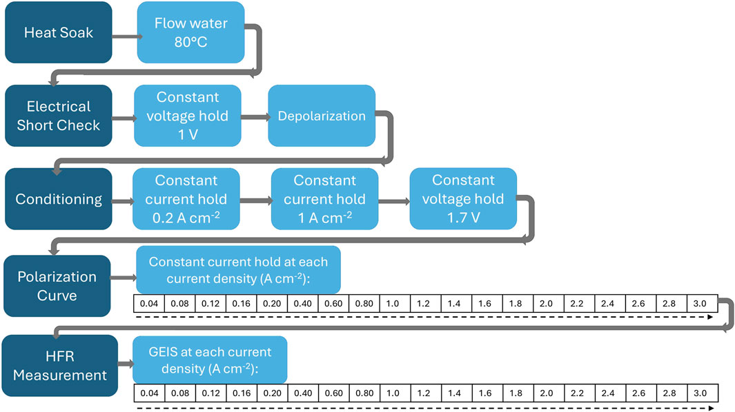
Figure 1. Flow chart of electrolyzer cell test procedure.
Health & safety warning
Depending on cell size, high electrical currents may be used when conducting this procedure. Refer to wire ampacity charts to ensure that electrical cables connecting the power supply and the PEM electrolyzer cell are appropriate for the amount of current being applied. Ensure that the electrical cables are properly secured to the PEM electrolyzer cell and that the cables are properly insulated. Use a multimeter to verify that the cell is de-energized (<1 V) before changing any electrical connections. Additionally, ensure the power supply or potentiostat is set to shut off when a specific upper voltage limit such as 2.5V is exceeded. In case of failure of the pump, fittings, or other problems that interrupt water flow to the cell, this voltage limit will shut down the cell and may prevent the cell from overheating and damaging components.
If the cell is not properly sealed, generated hydrogen can leak out and become a safety hazard. After cell build, nitrogen gas can be used to check the sealing of the cell. Using a nitrogen cylinder, apply approximately 30 psi of pressure simultaneously to both sides of the cell. Close the inlets and check for a pressure drop of the cell compartment, which would indicate insufficient sealing. When current is first applied to the cell, use a handheld combustible gas detector to check for leaks around the edges of the cell.
Hydrogen gas forms a flammable mixture with air or oxygen when it reaches a 4% volume fraction. This fraction is called the lower flammability limit (LFL). Test areas must be properly ventilated, and a hydrogen monitoring system should be used. If a hydrogen monitoring system is used, it is recommended to set a limit so that the cell will shut down in accordance with regulations set by the respective institution, or at 50% of the LFL at the highest, i.e., a 2% volume fraction of hydrogen in air or oxygen.
Cell components exposed to 80°C water can result in hot cell hardware surfaces. Always use gloves to handle the cell hardware, and allow the cell to cool before disassembling. Always wear safety glasses, and always use gloves to handle the cell, cell components, and test station equipment. Lab coats and safety shoes may also be necessary in some lab environments.
Equipment and supplies
Electrolyzer test setups vary widely between labs, but contain more or less the same components. Figure 2 shows an example schematic of a test setup. Cell hardware is commercially available, and an open source design is also available from NREL (Wrubel et al., 2023).
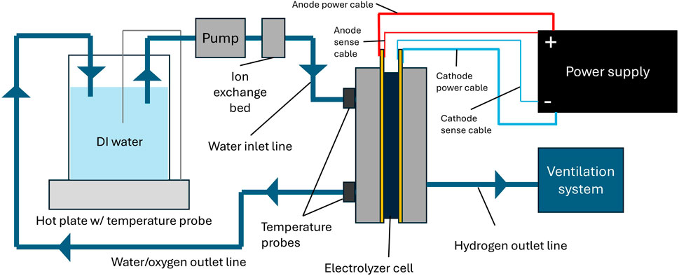
Figure 2. Schematic of typical PEM electrolyzer test station. Cathode inlet not pictured, assumed to be closed.
Water loop equipment
A recirculating water system is common for PEM electrolyzer testing. Water is pumped from the reservoir to an ion exchange resin, which removes any impurities before the water is delivered to the cell. Water passes through the cell and then back into the reservoir.
• DI water: Using ultrapure (>1 MΩ cm, ASTM Type 2) DI water is essential to avoid contaminating the electrolyzer cell. It is advised to monitor and maintain water purity throughout the duration of the test.
• Water reservoir: The most important concern in selecting a water reservoir is that it can withstand the highest desired operating temperature–usually 80°C.
• Heaters: For small test setups, a hot plate with a temperature probe can be sufficient for water heating. Larger reservoirs may require an immersion heater. In addition, some labs may choose to heat the cell itself using heating rods or heating pads for more precise temperature control. Importantly, temperature should be controlled to the inlet of the cell, but also measured at the outlet. This is crucial for more reproducible data sets. The temperature gradient between the inlet and the outlet should be kept below either 0.08°C cm-2 or 2°C, or whichever is lower, to avoid cell voltage fluctuations (Bender et al., 2019). Ensure that heater elements are only in proximity to compatible materials, and particularly keep them away from exhaust lines for hydrogen and oxygen.
• Pump: Should be able to provide 2 mL min-1 cm-2. For higher current densities the flow rate should be increased to keep the temperature difference between the inlet of the cell and the outlet below 2°C (Bender et al., 2019).
• Ion exchange resin: While not required, an ion exchange resin bed is strongly recommended to filter contaminants that might be introduced into the water loop due to cell component degradation. Note that the maximum temperature specification of the resin is required to be higher than the water temperature to avoid decomposition.
• Tubing and fittings: The anode and cathode sides of the cell must be electrically isolated from each other. Plastic tubing is appropriate, but ensure that the material can withstand the highest desired operating temperature. Dielectric fittings can also be used to isolate the cell, specifically, when metal tubing is used. To avoid contamination, metal tubing should be passivated prior to use using established passivation methods such as ASTM A967 or ASTM A380, for example.
Electrical equipment
There are generally two options for supplying power to an electrolyzer cell: power supplies and potentiostats/galvanostats. Potentiostats/galvanostats are high precision programmable power supplies capable of running complex techniques such as EIS and cyclic voltammetry (CV). However, they can be expensive, and it may be necessary to purchase boosters to reach the desired current densities. Power supplies can reach higher current densities at a much lower price, but they lack the capability to run EIS and some may lack accuracy at low currents. One solution that labs employ is to conduct EIS at low currents with a potentiostat/galvanostat, and apply larger currents with a power supply to run polarization curves and/or steady state testing without utilizing EIS diagnostics. This is an economical option, but great care must be taken when switching electrical connections. Before changing electrical connections, always shut off the potentiostat/galvanostat or power supply and use a multimeter to verify the cell potential has dropped below 1 V. This procedure limits the hazard of undesired electrical discharge.
If bolts are used for the power connection, they should be tightened with a wrench to the torque specified by the manufacturer. Loose bolts can cause high resistances which may cause overheating at the power connection. Voltage sense leads should be connected as close as possible to the cell components and care should be taken that they are not in contact with current carrying components.
Product gas handling
Product oxygen and hydrogen exit the electrolysis cell through the exhaust lines of the anode and cathode, respectively. Both exhaust streams ideally include a water gas separator, which in the anode case can also double as the water container. From these devices the water is either recycled into the cell (anode recirculation loop) or drained (anode and cathode) and the gas is exhausted typically into the laboratory exhaust ventilation system. A safety assessment according to the regulations of the respective institution should always be performed prior to generating hydrogen or oxygen gas.
Procedure
Step-by-step procedure
This protocol can be applied regardless of the cell components that are used. Cell components include porous transport media for anode and cathode, catalysts, and membranes. It is assumed that the user has determined a cell configuration that they want to characterize and have assembled the electrolyzer cell prior to conducting this protocol. More information on cell assembly can be found in the literature, e.g., Parimuha et al. (2025).
This protocol assumes the use of a potentiostat. With the exception of the EIS, the protocol can also be conducted with a power supply. For all steps involving an applied current, multiply the listed current density by the active area of the electrolyzer cell in square centimeters to obtain the appropriate total current. Note that while we recommend to always use 80°C for the entire conditioning procedure and initial performance measurements to ensure reproducible results between cells, subsequent experiments can also be conducted at different operating conditions, such as at 60°C cell temperature, for example,.
Heat soak
1. Set water temperature to 80°C. Begin flow of water through the electrolyzer cell. The flow rate should be at least 2 mL min−1 cm−2.
2. Allow water to flow through the cell until the temperature at the inlet and outlet have both reached 80°C, then another 10 min to ensure that the cell temperature has equilibrated, and the membrane is hydrated.
3. If a nitrogen cylinder is available, temporarily stop water flow and apply 30 psi of nitrogen to the cell. If an obvious leak or pressure drop is observed, do not proceed with the rest of the protocol as the cell is not properly sealed. After conducting the nitrogen leak test, resume flowing water and monitor the water temperature until both the inlet and outlet reach 80°C again. This test should always be conducted after the heat soak step, as the swelling of the membrane upon hydration helps seal the cell.
Electrical short check
4. Connect the positive power and sense leads (working) of the potentiostat/galvanostat to the anode side of the cell, and the negative power and sense leads (counter and reference) to the cathode side. The power leads should have a robust connection capable of carrying up to 3 A cm−2 of the electrolyzer cell.
5. Turn on the potentiostat/galvanostat and launch the software on the connected computer.
6. Most potentiostat/galvanostat software should have a readout of the open circuit voltage (OCV) of the cell. If the cell has been connected correctly, this should be 0 V or a small positive voltage <100 mV. If the OCV is negative or changing rapidly, check the potentiostat connections to the cell.
7. The short check is a two-step procedure which must be followed in the order below. Program the following procedure in the potentiostat software:
a. Constant voltage hold (i.e., chronoamperometry (CA)) at 1.0 V versus reference for 2 min. Record at least 1 point per second
b. Record voltage response (depolarization) with no applied voltage or current for 2 min. An OCV measurement can be used for this. Record at least 1 point per second
8. Run the program. In a non-shorted cell, the following behaviour should be observed:
a. During the CA step, the measured current will start high but almost immediately drop to 0 A or close to 0 A (see Figure 3A).
b. During the depolarization step, the measured voltage will be 1.0 V at the very beginning of the depolarization step and will decrease gradually throughout the depolarization step (see Figure 3B).
9. Observing one or more of the following behaviours could indicate the cell is shorted:
a. During the CA step, the measured current starts high and drops to a steady value > 40 mA cm-2 (see Figure 3A).
b. Measured voltage is < 0.9 V at the very beginning of the depolarization step (see Figure 3B).
c. During the depolarization step, voltage drops immediately to 0 V (see Figure 3B).
10. If a short is suspected, do not proceed with the rest of the protocol.
Conditioning
While electrolyzer conditioning protocols are still widely debated, it is agreed that proper conditioning of the cell leads to improved performance, including lower HFR and increased active sites (Wang et al., 2022). Therefore, the most important considerations are that the same conditioning procedure must be applied to cells intended for comparison and that the conditioning is complete, so that performance differences can be attributed to the cell components themselves (Bender et al., 2019). The following steps constitute an example of a conditioning protocol. Many other conditioning protocols can be found in the literature that target to activate the catalyst material, establish proton pathways and enable stable, repeatable and reproducible performance. Please note that the given values for voltage and current are based on previous published work (Parimuha et al., 2025; Lickert et al., 2023; Wang et al., 2022).
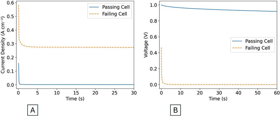
Figure 3. (A) Expected current behavior during 1 V hold step of short check. (B) Expected voltage behavior during depolarization step of short check.
If a cell was operated and then left idle for an extended period of time, a shortened “re-conditioning” procedure can be used with shorter hold times.
11. Program the following procedure in the potentiostat software:
a. Constant current hold (i.e., chronopotentiometry (CP)) at 0.2 A cm−2 – 30 min
b. Constant current hold (CP) at 1 A cm−2 – 30 min
c. Constant voltage hold (CA) at 1.7 V vs. reference – 15 h or until variation in current is less than 1% per hour (Lickert et al., 2023; Bender et al., 2019)
12. Run program and observe current response of step c for stability.
13. Upon first application of current, check around the cell for leaks using a handheld combustible gas detector.
Polarization curve
It has been shown that at least one “conditioning” polarization curve is required for a stable and repeatable voltage response (Lickert et al., 2023). Therefore, it is recommended to repeat the polarization curve procedure at least twice, and report only the last polarization curve measurement.
In this protocol, polarization curve and EIS measurements are listed separately for clarity. However, if equipment allows, it is recommended to perform them in combination, collecting both a constant current hold and an EIS spectrum at each current point before moving to the next one.
The maximum current of the polarization curve may be limited by the power supply or potentiostat used. Although 3.0 A cm−2 is used as the maximum here, some test setups may be able to reach 4.0 or 5.0 A cm−2. Do not apply any current over the limit of the power source or greater than the electrical cable ratings.
14. Program the following procedure in the potentiostat software:
a. Constant current holds (CP) for 2 min each from 0.04 A cm−2 to 0.2 A cm−2 in steps of 0.04 A cm−2, i.e. 0.04, 0.08, 0.12, 0.16, and 0.2 A cm−2. Record at least 1 point per 10 s
b. Constant current holds (CP) for 2 min each from 0.2 A cm−2 to 3.0 A cm−2 in steps of 0.2 A cm−2. Record at least 1 point per 10 s
c. Optionally, reverse steps a and b (step down current)
15. Ensure a maximum voltage limit of 2.5 V is set on the potentiostat.
16. Run the program with the water controlled to 80°C as set previously.
HFR measurement
Electrochemical impedance spectroscopy (EIS) is a well-established diagnostic for research and development of electrochemical systems. In depth information about this diagnostic can be found in the literature (Siracusano et al., 2018; Padgett et al., 2023; Gerhardt et al., 2021). This protocol takes an EIS spectrum at each of the current densities used in the polarization curve. A booster is required to reach high current densities, and not all boosters are capable of EIS. Perform EIS up to the highest current allowed by the potentiostat/galvanostat and booster, keeping in mind the perturbation amplitude.
17. Prior to performing EIS, ensure no wires, cables, or other conductive materials besides the power cables and voltage sense leads are touching the cell. Twisting positive and negative cables together can prevent electromagnetic noise, and the shortest possible cables should be used. The cables and potentiostat/galvanostat are often calibrated together and in that case shouldn’t be removed from the system.
18. Program the following procedure in the potentiostat/galvanostat software:
a. Optionally, potentiostatic electrochemical impedance spectroscopy (PEIS) at OCV, 100 kHz (or as high as equipment allows) to 1 Hz, 9 points per decade, perturbation +/- 10 mV
b. Galvanostatic electrochemical impedance spectroscopy (GEIS) at each current used in the polarization curve (not exceeding the maximum current for EIS on the potentiostat/galvanostat), 100 kHz (or as high as equipment allows) to 1 Hz, 9 points per decade, perturbation +/- 10 mA cm−2
19. Run the program. If a live display is available, observe the resulting Nyquist plot (Re(Z) on the x-axis, -Im(Z) on the y-axis) as the data is collected. A typical Nyquist plot is shown in Figure 4A. The points collected at the highest frequencies are most influenced by inductive wire contributions, therefore their -Im(Z) values are expected to be positive, and they appear below the x-axis. The progression to lower frequencies is expected to result in a more capacitive response of the system, therefore the -Im(Z) values become negative and the plot is expected to intercept the x-axis. The intercept point is defined as the high frequency resistance (HFR). If any irregularities are observed in the data, stop the measurement and troubleshoot for loose connections or similar anomalies that could affect the measurement.
Shutdown
20. Once all programs have finished, shut off potentiostat power. If using a power supply, turn applied current to 0 A, then shut off power supply. Shut off water pump, water heater, and cell heater if applicable. Using a multimeter, monitor the cell voltage until it drops below 1 V before disconnecting electrical cables. Wait for cell to cool before handling.
Results and example data, cautions and common interferences
All plots in this section contain fictitious data, intended to represent the expected trend of each technique.
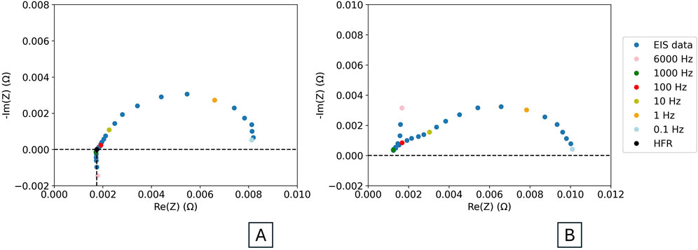
Figure 4. (A) Example EIS spectrum, with HFR value and frequencies indicated. (B) EIS spectrum with high frequency interference resulting from test setup, with frequencies indicated.
Short check
The short check consists of a 1 V hold step (see Figure 4A) followed by a depolarization step (see Figure 4B). Figure 3 shows the expected behavior during each step for a cell passing (solid blue line) or failing (dashed orange line) the short check.
During the 1 V hold step, the current in the passing cell drops quickly to a steady state value close to 0 A. This steady state value is referred to as the shunt current. The shunt current will almost never be exactly 0 A, but should be below 10 mA cm−2 in a passing cell. If the value is between 10 and 40 mA cm−2, a short is possible, but not certain. Within this range, knowledge of the cell components and their expected performance is necessary to diagnose if a short is present or not. The shunt current in a passing cell will depend on the thickness of the membrane and the other cell components, so it is important to run a short check with every test to get a sense of what is typical of the particular cell configuration being used. If the shunt current is higher than 40 mA cm−2, a short is likely. The failing shorted cell in Figure 3A has a shunt current of almost 300 mA cm−2, which would be considered high for any cell configuration. These current thresholds are based on experience at Nel Hydrogen. Cells containing thin membranes and/or rough porous transport media are more prone to shorting.
During the depolarization step, the voltage of a passing cell starts at 1 V and slowly decreases. The slope of the decreasing voltage will again depend on the cell configuration. If a short circuit is present, the voltage decay will be almost instantaneous, or the cell voltage may start well below 1 V. The 1 V hold and depolarization steps together are a useful diagnostic tool throughout the cell lifetime.
Polarization curves
Data should be expressed as current density in A cm-2 for easier comparison with results from different cell sizes as reported in the literature and the electrolysis community. To convert to current density from total current, divide the value in A by the active area of the cell in square centimeters to obtain a current density in A cm-2. Average the recorded current and voltage data of each current step into data points, convert them into current density if needed and plot them as voltage vs. current density. Researchers should also review the data in the form of voltage vs. time, as shown in Figure 5A, to confirm that the data constitutes a clean staircase. Deviations from this staircase may indicate contamination or other irregularities that may have impacted the experiment (Padgett et al., 2024).
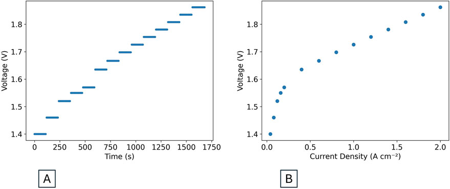
Figure 5. (A) Raw polarization curve data in the form of voltage vs. time. (B) Processed polarization curve in the form of voltage vs. current density.
Each step is a different current setpoint. If the voltage is relatively stable through the duration of each step, as in Figure 5A, the average voltage over the whole of each current point can be reported. If the voltage takes some time to stabilize after the current is changed, report an average over a stable region of at least 15s. The step length used for recording the polarization curve can be adjusted based on how quickly the voltage response stabilizes. If the voltage does not stabilize, the reason needs to be explored as the data may indicate contamination or other experimental challenges (Padgett et al., 2024). To create the final polarization curve, average the voltage and current data at each step and plot the voltage vs. the current density points, as seen in Figure 5B. The step-by-step method outlined in this protocol is preferred over a linear-sweep voltammetry (LSV) approach, as it allows the voltage response of the cell to stabilize so that the behavior described above can be observed.
Further analysis of the polarization curve data to determine contributions from different processes is useful, and outlined well in a EU-harmonized protocol (Malkow et al., 2018). Performing a reversed polarization curve (from high to low current) is not always necessary, but it can sometimes reveal more information about the cell, such as presence of contaminants (Padgett et al., 2024).
EIS–HFR measurement
The HFR is typically calculated from EIS data by finding the value of Re(Z) at which -Im(Z) is 0 Ohm. This can be achieved by interpolating the high-frequency data and determining the intercept of the Nyquist EIS plot with the x-axis.
Many electrochemical software programs are also capable of extracting HFR. Figure 4A shows where on the EIS curve to extract an HFR value.
As with current, resistance should be reported in area-specific units. To obtain the area-specific resistance in Ω cm2, multiply the resistance in Ohms by the cell active area in square centimeters. Note that this is different from the calculation for current density described in the “Polarization Curves” section, as the measured resistance is inversely proportional to the active area of the cell.
Figure 4B shows an example of an EIS spectrum with interference from the test setup. Note how the spectrum does not cross the Re(Z) axis. The HFR can therefore not be extracted from this data set. Much more detail is available in literature about parasitic and inductive effects at high and low frequencies (Hensle et al., 2023; Franzetti et al., 2023). EIS should be conducted up to the highest frequency allowed by the user’s potentiostat. High frequencies allow for analysis of resistance without influence of charge transfer (Dastafkan et al., 2023).
It is possible to extract much more information from EIS data than what is outlined in this protocol. Use of EIS data to help deconvolute voltage contributions from different cell components and processes is well described in literature (Siracusano et al., 2018; Sánchez Batalla et al., 2024).
HFR free voltage calculation
Often, polarization curve and EIS data is combined to report HFR-free voltages. This means that the voltage loss from ohmic drop has been subtracted from the cell voltage. This helps isolate contributions of non-ohmic voltage losses, such as from catalyst utilization (Padgett et al., 2023). To obtain an HFR-free voltage at a certain current, the following equation (Equation 1) can be used:
Where
Data availability statement
The original contributions presented in the study are included in the article/supplementary material, further inquiries can be directed to the corresponding author.
Author contributions
SF: Writing – original draft, Writing – review and editing. RO: Writing – original draft, Writing – review and editing. JY: Writing – review and editing. GB: Writing – review and editing. MC: Writing – original draft, Writing – review and editing. KA: Writing – review and editing, Funding acquisition.
Funding
The author(s) declare that financial support was received for the research and/or publication of this article. This work was funded by the United States Department of Energy under the program “Benchmarking Advanced Water Splitting Technologies: Best Practices in Materials Characterization” (Award #: DE-EE0008092). This work was authored in part by the National Renewable Energy Laboratory for the U.S. Department of Energy (DOE) under Contract No. DE-AC36-08GO28308. Funding provided by the U.S. DOE Office of Energy Efficiency and Renewable Energy (EERE) Hydrogen and Fuel Cell Technologies Office (HFTO).
Acknowledgments
The authors would like to acknowledge George Roberts of Nel Hydrogen for steering the benchmarking effort, and Ramchandra Gawas of Lawrence Berkeley National Laboratory for helpful discussion of the protocol.
Conflict of interest
Authors SF, RO, MC, and KA were employed by the company Nel Hydrogen.
The remaining authors declare that the research was conducted in the absence of any commercial or financial relationships that could be construed as a potential conflict of interest.
Generative AI statement
The author(s) declare that no Generative AI was used in the creation of this manuscript.
Publisher’s note
All claims expressed in this article are solely those of the authors and do not necessarily represent those of their affiliated organizations, or those of the publisher, the editors and the reviewers. Any product that may be evaluated in this article, or claim that may be made by its manufacturer, is not guaranteed or endorsed by the publisher.
Author disclaimer
The views expressed in the article do not necessarily represent the views of the DOE or the U.S. Government. The U.S. Government retains and the publisher, by accepting the article for publication, acknowledges that the U.S. Government retains a nonexclusive, paid-up, irrevocable, worldwide license to publish or reproduce the published form of this work, or allow others to do so, for U.S. Government purposes.
References
Appelhaus, S., Ritz, L., Pape, S.-V., Lohmann-Richters, F., Kraglund, M. R., Jensen, J. O., et al. (2024). Benchmarking performance: a round-robin testing for liquid alkaline electrolysis. Int. J. Hydrog. Energy 95, 1004–1010. doi:10.1016/j.ijhydene.2024.11.288
Bender, G., Carmo, M., Smolinka, T., Gago, A., Danilovic, N., Mueller, M., et al. (2019). Initial approaches in benchmarking and round robin testing for proton exchange membrane water electrolyzers. Int. J. Hydrog. Energy 44 (18), 9174–9187. doi:10.1016/j.ijhydene.2019.02.074
Dastafkan, K., Wang, S., Song, S., Meyer, Q., Zhang, Q., Shen, Y., et al. (2023). Operando monitoring of gas bubble evolution in water electrolysis by single high-frequency impedance. EES Catal. 1 (6), 998–1008. doi:10.1039/D3EY00182B
Ehelebe, K., Schmitt, N., Sievers, G., Jensen, A. W., Hrnjić, A., Collantes Jiménez, P., et al. (2022). Benchmarking fuel cell electrocatalysts using gas diffusion electrodes: inter-lab comparison and best practices. ACS Energy Lett. 7 (2), 816–826. doi:10.1021/acsenergylett.1c02659
Franzetti, I., Pushkarev, A., Chan, A.-L., and Smolinka, T. (2023). Parasitic effects in impedance spectrum of PEM water electrolysis cells: case study of high-frequency inductive effects. Energy Technol. 11 (12), 2300375. doi:10.1002/ente.202300375
Gerhardt, M. R., Pant, L. M., Bui, J. C., Crothers, A. R., Ehlinger, V. M., Fornaciari, J. C., et al. (2021). Method—practices and pitfalls in voltage breakdown analysis of electrochemical energy-conversion systems. J. Electrochem. Soc. 168 (7), 074503. doi:10.1149/1945-7111/abf061
Hensle, N., Brinker, D., Metz, S., Smolinka, T., and Weber, A. (2023). On the role of inductive loops at low frequencies in PEM electrolysis. Electrochem. Commun. 155, 107585. doi:10.1016/j.elecom.2023.107585
Lickert, T., Fischer, S., Young, J. L., Klose, S., Franzetti, I., Hahn, D., et al. (2023). Advances in benchmarking and round robin testing for PEM water electrolysis: reference protocol and hardware. Appl. Energy 352, 121898. doi:10.1016/j.apenergy.2023.121898
Malkow, T., Pilenga, A., Tsotridis, G., and De Marco, G. (2018). EU harmonised polarisation curve test method for low-temperature water electrolysis. Luxembourg: Publications Office of the European Union.
Ozturk, M., and Dincer, I. (2021). An integrated system for ammonia production from renewable hydrogen: a case study. Dev. Hydrog. Fuel Cell Technol. 46 (8), 5918–5925. doi:10.1016/j.ijhydene.2019.12.127
Padgett, E., Adesso, A., Yu, H., Wrubel, J., Bender, G., Pivovar, B., et al. (2024). Performance losses and current-driven recovery from cation contaminants in PEM water electrolysis. J. Electrochem. Soc. 171 (6), 064510. doi:10.1149/1945-7111/ad576b
Padgett, E., Bender, G., Haug, A., Lewinski, K., Sun, F., Yu, H., et al. (2023). Catalyst layer resistance and utilization in PEM electrolysis. J. Electrochem. Soc. 170 (8), 084512. doi:10.1149/1945-7111/acee25
Parimuha, M. R., Young, J. L., Lee, J. K., Yilmaz, A., Diaz-Abad, S., Gawas, R., et al. (2025). Proton exchange membrane electrolysis benchmarking: identifying and removing sources of variation in test stations, hardware, and membrane electrode assembly fabrication. Int. J. Hydrog. Energy 114, 486–496. doi:10.1016/j.ijhydene.2025.02.443
Rogler, M., Suermann, M., Wagner, R., Thiele, S., and Straub, J. (2023). Advanced method for voltage breakdown analysis of PEM water electrolysis cells with low iridium loadings. J. Electrochem. Soc. 170 (11), 114521. doi:10.1149/1945-7111/ad0b74
Sánchez Batalla, B., Bachmann, J., and Weidlich, C. (2024). Investigation of the degradation of proton exchange membrane water electrolysis cells using electrochemical impedance spectroscopy with distribution of relaxation times analysis. Electrochimica Acta 473, 143492. doi:10.1016/j.electacta.2023.143492
Siracusano, S., Trocino, S., Briguglio, N., Baglio, V., and Aricò, A. S. (2018). Electrochemical impedance spectroscopy as a diagnostic tool in polymer electrolyte membrane electrolysis. Materials 11 (8), 1368. doi:10.3390/ma11081368
Wang, W., Li, K., Ding, L., Yu, S., Xie, Z., Cullen, D. A., et al. (2022). Exploring the impacts of conditioning on proton exchange membrane electrolyzers by in situ visualization and electrochemistry characterization. ACS Appl. Mater. Interfaces 14 (7), 9002–9012. doi:10.1021/acsami.1c21849
Wrubel, J., Ware, S., Schaffer, C., Allen, M., Klein, E., Rice, R., et al. (2023). NREL 25-Cm2 high-pressure low-temperature electrolysis cell hardware. Open Source. doi:10.7799/2205626
Keywords: PEM electrolyzer, polarization curve, electrochemical impedance spectroscopy (EIS), protocol, test stand, experimental procedure
Citation: Fortiner S, Ouimet R, Young JL, Bender G, Carmo M and Ayers K (2025) A harmonized protocol to assess the single-cell performance of proton exchange membrane water electrolyzers. Front. Energy Res. 13:1549219. doi: 10.3389/fenrg.2025.1549219
Received: 20 December 2024; Accepted: 27 May 2025;
Published: 17 June 2025.
Edited by:
Ellen B. Stechel, Arizona State University, United StatesCopyright © 2025 Fortiner, Ouimet, Young, Bender, Carmo and Ayers. This is an open-access article distributed under the terms of the Creative Commons Attribution License (CC BY). The use, distribution or reproduction in other forums is permitted, provided the original author(s) and the copyright owner(s) are credited and that the original publication in this journal is cited, in accordance with accepted academic practice. No use, distribution or reproduction is permitted which does not comply with these terms.
*Correspondence: Marcelo Carmo, bWNhcm1vQG5lbGh5ZHJvZ2VuLmNvbQ==