 Meital Shviro1*
 Sun Young Kang2Fernando Diaz Campos1Virginia Larson1
 Sandip Maurya2Daniel Philip Leonard2
- 1National Renewable Energy Laboratory, Chemistry and Nanoscience Center, Golden, CO, United States
- 2Los Alamos National Laboratory, Materials Synthesis and Integrated Devices Group (MPA-11), Los Alamos, NM, United States
The increasing demand for efficient and sustainable hydrogen production has driven significant advancements in water electrolysis technologies. Among these, liquid alkaline water electrolysis (LAWE) stands out for its cost-effectiveness and scalability. This manuscript establishes best practices and standardized testing procedures for single-cell LAWE, focusing on the use of nickel foam as both anode and cathode substrates, while incorporating catalysts such as nickel-iron layered double hydroxide (NiFe-LDH) as the anode material and nickel-molybdenum on carbon (NiMo/C) as the cathode material. By providing detailed guidelines on material preparation, cell assembly, and performance evaluation, this work offers a comprehensive framework to improve reproducibility and ensure consistency. The results demonstrate that applying these best practices minimizes variability across different laboratories and experimental setups, laying the groundwork for more robust comparisons and accelerating progress in LAWE research.
1 Introduction
In recent years, there has been a growing interest in developing advanced materials and technologies for water electrolysis, driven by the increasing demand for sustainable hydrogen production (Franco and Giovannini, 2023; Nazir et al., 2020; Wang et al., 2021). Liquid alkaline water electrolysis (LAWE) remains one of the most established and economically viable methods for large-scale hydrogen generation due to its reliance on abundant and inexpensive components, such as nickel-based electrodes (Ansar et al., 2021; Lohmann-Richters et al., 2021; Santos et al., 2013; Schalenbach et al., 2018; Zeng and Zhang, 2010) Despite its maturity, ongoing advancements in electrode development (Demnitz et al., 2024; Karacan et al., 2022b) and cell design (Phillips et al., 2017; Rodríguez and Amores, 2020) continue to improve its efficiency and durability, maintaining LAWE’s relevance.
A fundamental step in advancing LAWE technologies is the reliable evaluation of components and cell configurations through single-cell testing (Bender et al., 2019; Lickert et al., 2023; Tsotridis and Pilenga, 2021). Single-cell testing provides researchers with crucial insights into the electrochemical performance, durability, and scalability of new materials. However, the absence of standardized testing protocols and methodologies has led to inconsistencies in the data reported by different research groups, often resulting in unproductive research directions and difficulties reproducing promising results. Contrasting cases in the literature reveal how varying experimental approaches—such as differences in electrolyte composition, flow rates, and electrode preparation—can produce significantly different performance metrics (Marquez et al., 2024). For instance, Appelhaus et al. (2024) emphasize that the iron content in the electrolyte and precise temperature control are critical factors in achieving reproducible results across different laboratories. These findings underscore the challenges of comparing data across studies and highlight the urgent need for standardized methodologies to ensure that observed performance differences stem from intrinsic material properties rather than procedural variations.
This study seeks to address and mitigate the challenges of evaluating the reproducibility of single-cell testing for LAWE under controlled and standardized conditions. By implementing a unified testing protocol and practices across two laboratories and comparing performance using standardized materials and methodologies, the study seeks to identify and minimize sources of variability. Drawing inspiration from previous round-robin testing initiatives in PEM and alkaline electrolysis, this work aspires to establish a foundation for more consistent and reliable testing practices, enabling accurate benchmarking of materials and accelerating advancements in the field.
2 Protocol scope
2.1 Scope and applicability
The objective of this manuscript is to establish best practices and standardized protocols for single-cell testing in LAWE. This study focuses on ensuring reproducibility and reliability in performance evaluation using Ni foam, NiFe-LDH, and NiMo/C. The protocol outlines detailed procedures for evaluating activity in 30 wt% KOH at 80°C, aiming to minimize variability and enable consistent benchmarking across different laboratories and experimental setups.
2.2 Personnel qualifications/responsibilities
All personnel should be trained to handle chemicals and mitigate chemical hazards.
2.3 Health and safety warming
Chemical Hazards–This test protocol uses a concentrated base for the preparation of the electrolyte. Follow SDS safety precautions when handling concentrated potassium hydroxide. The concentrated base should be mixed in a fume hood. Standard personal protective equipment, including safety glasses, lab coat, and gloves (base-compatible), must be worn.
Electrical hazards- Before disassembling the cell, ensure the power source is turned off and disconnected. Confirm that the cell is fully discharged to prevent personal injury and avoid the risk of short-circuiting during disassembly.
Heat hazard- Allow the cell to cool completely before handling to avoid injury from contact with hot components. Metal parts of the cell, being excellent heat conductors, can retain high temperatures even after the system is powered down.
Waste Handling–All waste electrolytes, rinsing solutions, and cleaning residues must be collected and disposed of according to local hazardous waste disposal regulations. Use designated waste containers, label them as “Alkaline Waste,” and store them in an appropriate location until disposed of through an authorized hazardous waste service. Ensure all waste containers are securely closed when not in use to prevent leaks or spills.
2.4 Equipment and supplies
To complete the testing properly, researchers will be required to have this list of equipment and supplies.
2.4.1 Electrochemical testing equipment
Potentiostat
Electrochemical impedance spectroscopy (EIS) setup
Power supply
2.4.2 Cell components
Single-cell test fixture with anode and cathode flow fields made of nickel
Gaskets from Polytetrafluoroethylene (PTFE) (anode, cathode and separator)
Zirfon™ separator (Perl UTP 500 by Agfa) should be soaked in DI water for at least 1 h
Nickel foam as baseline electrodes (300 µm thick, Recemat BV, Netherlands)
2.4.3 Fluid handling tools
Peristaltic or diaphragm pumps for electrolyte flow
Tubing and connectors compatible with alkaline solutions
Separate anolyte and catholyte reservoirs, either interconnected via tubing to maintain concentration balance or used independently without interconnection. In the latter case, monitoring of electrolyte density and concentration should be implemented to ensure consistency during operation.
Pressure gauges or transducers can be added to the fluid inlets to prevent potential damage to the cell from over-pressurization. These tools allow real-time monitoring of inlet pressure, enabling prompt intervention in case of excessive pressure buildup and reducing the risk of leaks or cell damage.
2.4.4 Temperature control
Thermocouple for monitoring cell temperature
Thermocouple for controlling and monitoring cell inlet temperature
Heater with temperature controller
Heating components such as rod heaters or heating pads ensure uniform and efficient temperature control of the cell, Figure 1 illustrates the cell setup integrated with heating pads or heating rods.
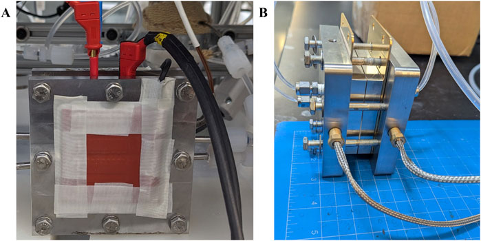
Figure 1. Images illustrating the cell setup integrated with (A) heating pads, (B) heating rods.
2.4.5 Electrolyte preparation
Potassium hydroxide (KOH) pellets should be the purest with <10 ppm of Fe salt. (pellets for analysis EMSURE®) Deionized (DI) water (from Milli-Q IQ 7000 Water Purification system)
2.4.6 Miscellaneous tools
Scissors (for trimming electrode and separator materials)
Torque wrench for bolt tightening
2.5 Recommended reading
1. S. Appelhaus et al. International Journal of Hydrogen Energy 95, 1004 (2024)
2. C. Karacan et al. international journal of hydrogen energy 47 (7), 4294 (2022)
3 Procedure
3.1 Step-by-step procedure
3.1.1 Electrode preparation
3.1.1.1 Anode electrode
A precursor solution was prepared by dissolving 0.04 M Ni(NO3)2·6H2O (Sigma-Aldrich, United States) and 0.01 M Fe(NO3)3·9H2O (Sigma-Aldrich, United States) in deionized (DI) water, followed by stabilization overnight. Nickel foam with dimensions of 2.5 × 5.0 cm2 was cleaned by sonication in ethanol for 10 min, thoroughly rinsed with DI water, and dried. The foam was then used as the working electrode in a three-electrode setup, with a platinum mesh as the counter electrode and a hydrogen electrode as the reference electrode. Electroplating was carried out at a current density of −13 mA/cm2 for 14 min in the N2-purged precursor solution, following stabilization at open circuit voltage for 5 min. A potentiostat (Bio-Logic, France) was used for process control. After electroplating, the electrode was rinsed with DI water and dried in a vacuum oven at 60°C for 2 h. This process results in a catalyst loading of 5.0 mg/cm2 ±0.05 mg on Ni Foam. Scanning Electron Microscopy (SEM) images of the NiFe-LDH coating on Ni foam are presented in Figure 2.
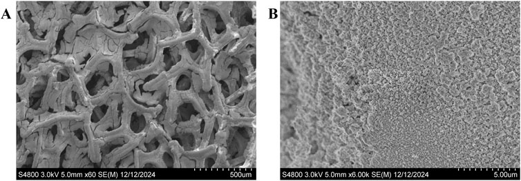
Figure 2. SEM images of NiFe-LDH electrodeposit on Ni foam at different magnifications. (A) Low-magnification image showing the porous structure of the Ni foam substrate with the integrated NiFe-LDH coating. (B) High-magnification image highlighting the surface morphology and uniform coverage of the NiFe-LDH coating.
3.1.1.2 Cathode electrode
For the cathode, a mixture of NiMo/C powder (Pajarito Powder, United States, 50 wt.% NiMo, BET surface area 500 m2/g), 5% Nafion dispersion (Chemours, United States), and 1-propanol (Sigma-Aldrich, United States) was prepared and ultrasonicated. The weight ratio of catalyst powder to 1-propanol was 1:100, with the Nafion dispersion content set to 23.16%. The slurry was sprayed onto pre-cleaned Ni foam using a spray coater (Sonotech, United States) to achieve a target catalyst loading of 0.7 mgmetal/cm2. After spraying, the electrode was dried in a vacuum oven at 60°C for 2 h. The resulting morphology of the NiMo/C-coated cathode is shown in Figure 3.
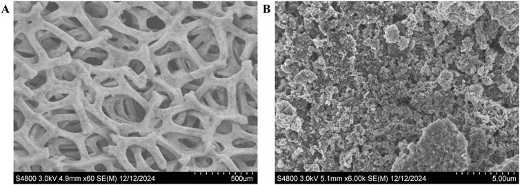
Figure 3. SEM images of NiMo/C-coated nickel foam electrodes. (A) Low-magnification image showing the porous structure and uniform coating on the Ni foam, and (B) high-magnification image illustrating the uniform deposition of NiMo/C on the foam surface.
While Nafion is widely used as a binder due to its excellent proton conductivity and ability to provide mechanical stability to the catalyst layer, its application in alkaline environments presents challenges (Ahmad et al., 2022). Nafion is prone to degradation due to hydrolysis or decomposition of its sulfonic acid groups, leading to a loss in ionic conductivity and mechanical integrity over time (Madhav et al., 2023). Despite these limitations, Nafion was chosen in this study because of its widespread availability, ease of use, and proven performance in short-term experiments (Demnitz et al., 2024; Kakati et al., 2023; Karacan et al., 2022b; Zappia et al., 2022).
3.1.2 Prepare the electrolyte solution
1. Prepare electrolyte solution with 30 wt.% of KOH (potassium hydroxide, pellets for analysis EMSURE®., Millipore) The volume of electrolyte prepared should be enough to fill the reservoirs. (30 wt% KOH: 452.1 g KOH in 870 mL of DI, density of 1.286 g/mL 35°C)
2. Carefully fill the reservoirs with the prepared KOH electrolyte.
3.1.3 Assemble the single cell
3. Rinse the nickel flow fields with DI water and dry them with nitrogen gas.
4. Assembly steps for the single-cell configuration are illustrated in Figure 4. Place the flow field on the endplate, then place the cathode gasket (250 µm) followed by the cathode Ni-foam (cut to 5 cm2), which should be trimmed to fit neatly within the gasket. Next add the separator gasket and the Zirfon separator (4 cm × 5 cm), trimming it to size as needed. Continue by placing the anode gasket (250 µm) and the anode Ni-foam (cut to 5 cm2), also trimmed to fit neatly within the gasket. Position the flow field and finally, secure the top end-plate.
5. Once all components are in place, insert the bolts and hand-tighten them to prepare for proper compression. Once the cell is ready to be torqued, tighten the bolts in a star-pattern and in stages. If 50 in-lbs is the desired final torque, first apply 25 in-lbs, then 35 in-lbs, before finally coming to the desired cell torque. Proper application of torque will minimize the risk of electrolyte leakage from cell components and improve repeatability between measurements.
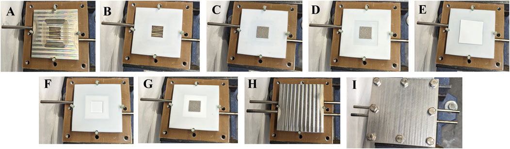
Figure 4. Assembly process of the single-cell setup. (A) Placement of the flow field on the endplate. (B) Cathode gasket positioned over the flow field. (C) Cathode Ni-foam trimmed to 5 cm2, fitted within the cathode gasket. (D) Placement of the separator gasket. (E) Zirfon separator positioned on the separator gasket. (F) Placement of the anode gasket. (G) Anode Ni-foam fits neatly within the anode gasket. (H) Final placement of the flow field on the top layer. (I) Securing the assembly with the top endplate.
3.1.4 Connect the cell to testing equipment
6. Connect the inlet and outlet tubing to the flow fields, and ensure the connections are properly tightened.
7. Turn on the pumps and set the flow rate to 50 mLmin−1. Inspect the connections for any signs of leakage while flowing the electrolyte. If a leak is detected, consider using Teflon tape or appropriate sealing material to secure the fittings.
8. Connect the thermocouple to the cell, ensuring proper placement for accurate temperature monitoring.
9. Once the electrolyte flow is established in the cell, begin increasing the temperature for both the anode and cathode inlets, as well as the overall cell temperature. Initially, set the temperature to 60°C and allow it to stabilize. Once the system maintains stability at 60°C, increase the temperature to 80°C and ensure it stabilizes before proceeding with testing.
3.1.5 Electrochemical testing
10. Connect the anode and cathode current collectors to the power supply and measurement device. If the cell lacks dedicated current collectors, establish the connection directly through the flow fields.
11. Set the experimental protocol as follows:
• Begin the experimental protocol with a 1-h stabilization period at open circuit voltage (OCV) to ensure the system reaches a steady state.
• Perform polarization curve measurements, starting from 2.5 V and decreasing to 1.4 V, with a 60-s hold at each potential and steps of 0.05 V. Then reverse the sequence, increasing from 1.4 V back to 2.5 V, holding for 60 s at each step.
• After completing the initial polarization curve, condition the cell at 2.0 V for 24 h.
• Following conditioning, conduct a second polarization curve measurement, again from 2.5 V to 1.4 V, but this time holding for 120 s at each potential and steps of 0.05 V. Reverse the sequence from 1.4 V back to 2.5 V with a 120-s hold at each step.
• Finally, perform EIS measurements at each potential to analyze the cell’s resistance and dynamics.
3.1.6 Data recording and standardization
12. Normalize the data to the active electrode area (5 cm2) for reporting
13. Ensure reproducibility by repeating the test at least three times under identical conditions.
3.2 Sample handling and preservation
1. Use the highest purity of KOH available, ideally containing ∼5–10 ppm of Fe, to minimize the on-affect performance.
2. Ensure that all connections and tubing are made from materials compatible with KOH and resistant to degradation. Avoid using stainless steel, as Fe leaching improves performance metrics (Appelhaus et al., 2024).
3. Handle separators and electrodes with care to avoid damage or contamination. Keep separators wet and in a stable, flat position to maintain their integrity and functionality.
3.3 Computer hardware and software
The potentiostat software is necessary for performing electrochemical tests and may also support data analysis.
4 Results and discussion
The following section presents the results obtained using the outlined testing protocol, with Ni foam electrodes serving as the baseline components (300 μm and a density of 500 gm−2). Two different cell designs were employed in the study, differing primarily in the structure of their flow fields. The cell used by NREL features a meandering flow field (Appelhaus et al., 2024; Karacan et al., 2022a), while the cell used by LANL incorporates a commercial serpentine nickel flow field (Fuell Cell Technologies, Inc.) (Figure 5).
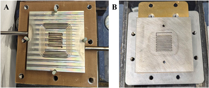
Figure 5. Images illustrating the two flow field designs used in the study. (A) Meandering flow field employed in the NREL cell. (B) Serpentine nickel flow field used in the LANL cell.
As shown in Figure 6, the performance curves measured at 80°C after the conditioning procedure exhibit a deviation of less than 30 mV at a current density of 0.5 A/cm2. Despite these differences in flow field design, the standardized testing protocol and consistent experimental conditions, including temperature control and heating methods, resulted in very small deviations.
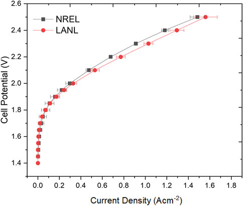
Figure 6. Performance comparison of experiment sets at 80°C after the conditioning step using Ni foam as both anode and cathode.
The polarization curves further compare the performance of electrochemical cells tested using NiFe-LDH coated on Ni foam as the anode and NiMo/C coated on Ni foam as the cathode (Figure 7). The integration of these catalysts was specifically implemented to evaluate the reproducibility of the experimental conditions and testing protocol across the two labs. Both labs exhibit a similar trend at lower current densities, indicating consistent performance under low current densities (<1.5 Acm−2) with a deviation of 30 mV at 1 A cm−2.
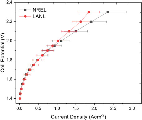
Figure 7. Comparison of polarization curves at 80°C after the conditioning step, using NiFe-LDH coated on Ni foam as the anode and NiMo/C coated on Ni foam as the cathode.
However, at higher current densities, deviations between tests within each lab and between the two labs become more pronounced, reaching approximately 100 mV at 1.8 A/cm2. This increased disparity can likely be attributed to variations in electrolyte flow rates (Abdelghani-Idrissi et al., 2021), and inconsistencies in cell assembly, including gasket alignment and electrode positioning (Xia et al., 2023). Furthermore, variations in electrode surface morphology and coating uniformity may influence bubble detachment and distribution, amplifying the observed differences at higher current densities (Bae et al., 2022; Dastafkan et al., 2023). For a better understanding of the performance deviations observed at high current densities, we conducted SEM characterization and elemental composition analysis of the electrodes after electrochemical testing (Figure 8). The SEM images of the NiFe-LDH electrode reveal significant delamination of the catalyst layer, exposing the underlying Ni foam. Additionally, the exposed areas exhibit aggregates that were not present on the catalyst layer before testing (Figure 8A). Similarly, the NiMo/C electrode displays pronounced delamination of the catalyst layer after testing, indicating structural degradation that likely impacts its electrochemical performance (Figure 8B). Elemental analysis further supports these observations. SEM-EDS was employed to assess the elemental composition of the catalyst layers both before and after testing (Figures 8C,D). For the NiFe-LDH electrode, the initial composition was 59% O, 23% Fe, and 6% Ni. After testing, a significant leaching of Fe was observed, accompanied by an increase in Ni content. Areas where the catalyst delaminated revealed a surface predominantly composed of Ni, corresponding to the underlying Ni foam (Figure 8C). On the cathode side, SEM-EDS analysis showed an initial catalyst composition of 13% Ni, 2% Mo, 26% F, and 40% C. After testing, the fluorine content—originating from Nafion used as a binder—decreased by half, indicating binder degradation. More notably, the Mo content decreased substantially, from 1.7 ± 0.3 at. % to 0.27 ± 0.14 at. %, suggesting significant leaching of this critical active component. In contrast, the carbon and nickel content of the catalyst layer remained relatively constant. Interestingly, despite the possibility of redeposition of dissolved metals from the electrolyte onto the cathode during testing, no substantial redeposition of Fe or Mo was detected on either the cathode catalyst layer or the exposed Ni foam after testing. These findings highlight the structural and compositional changes occurring during testing, emphasizing the critical role of material stability in ensuring consistent performance, particularly at elevated current densities.
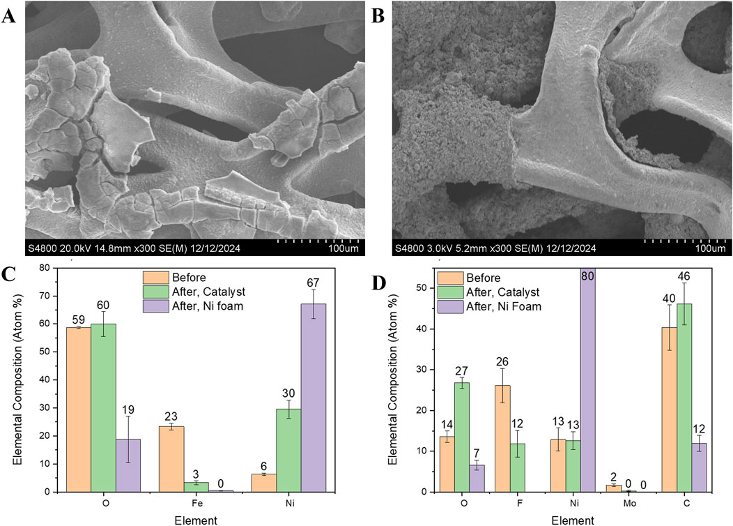
Figure 8. SEM images and elemental composition of the electrode after the electrochemical testing. (A) NiFe-LDH (B) NiMo/C, (C, D) Comparison of catalyst layer elemental composition as determined by SEM-EDS before and after testing. “After, Ni foam” refers to the exposed Ni foam after the delamination of the catalyst. Standard deviation is shown for N ≥ 3 regions.
The overall similarity observed at lower current densities underscores the importance of best practices and standardized protocols in ensuring reproducible baseline performance across different laboratories. This finding demonstrates that reducing procedural variability and consistently applying the same working protocol enables reliable and comparable results, even when using varied experimental setups. This consistency aligns with findings from previous benchmarking studies, such as those by Karacan et al. (2022a), which emphasize the value of harmonized methodologies in minimizing inter-laboratory variability. Similarly, insights from Appelhaus et al. (2024) highlight the crucial role of well-controlled testing environments in isolating material performance from external factors, including operational inconsistencies.
Despite inherent differences in flow field designs—meandering versus serpentine—the adherence to a unified testing framework has minimized performance discrepancies, enabling meaningful comparisons and reliable evaluations. However, the pronounced deviations observed at higher current densities are likely influenced by the compromised stability of the electrodes during testing. Structural degradation and material leaching observed in postmortem analyses may amplify inconsistencies under these more demanding conditions. This highlights the system’s sensitivity to operational parameters and the critical need for further standardization. Addressing factors such as flow field design, bubble management, and catalyst stability are essential to ensure uniformity and reproducibility in performance outcomes, particularly at elevated current densities.
5 Conclusion
This study emphasizes the critical role of consistent experimental conditions and standardized protocols in obtaining reliable and reproducible results in single-cell testing for LAWE. By comparing performance across two laboratories using different cell designs yet adhering to a unified testing framework, the findings illustrate that precise procedural alignment and meticulous control of operational variables are key to minimizing deviations and enabling meaningful comparisons. These results support the necessity of harmonized practices to advance the field, improve the benchmarking of electrode materials, and foster greater confidence in the reproducibility of testing outcomes across laboratories.
6 Quality control and quality assurance
6.1 Instrument or method calibration and standardization
Several aspects of single cell testing require calibration and standardization. The electrolyte solution preparation should be consistent, the cell assembly and regular calibration of equipment such as potentiostat and temperature controllers. Moreover, verifying the purity of the Ni foam and uniformity of catalyst coatings, as well as cross-verifying data trends between independent tests. These measures are critical for minimizing variability and ensuring the robustness of the testing protocol across different laboratories.
6.2 Cautions
Contamination can significantly impact performance results; ensure all components are thoroughly cleaned and properly handled before testing.
6.3 Common issues
Several common issues can arise during single-cell testing, potentially affecting performance and data reproducibility. Gas bubble accumulation on electrode surfaces can impede mass transport, leading to increased resistance and variability in results, particularly at higher current densities. Improper cell assembly, such as misaligned gaskets or uneven electrode placement, can cause electrolyte leakage or inconsistent sealing. Contamination of electrodes or electrolytes may introduce artifacts, underscoring the importance of rigorous cleaning procedures. Additionally, inconsistencies in temperature regulation or flow rate control can impact performance.
Data availability statement
The datasets presented in this study can be found in online repositories. The names of the repository/repositories and accession number(s) can be found in the article/supplementary material.
Author contributions
MS: Conceptualization, Data curation, Formal Analysis, Investigation, Methodology, Resources, Supervision, Validation, Writing – original draft, Writing – review and editing. SK: Data curation, Formal Analysis, Investigation, Writing – review and editing. FC: Data curation, Formal Analysis, Investigation, Writing – review and editing. VL: Data curation, Formal Analysis, Writing – review and editing. SM: Conceptualization, Writing – review and editing. DL: Conceptualization, Data curation, Investigation, Methodology, Resources, Supervision, Writing – review and editing, Formal Analysis.
Funding
The author(s) declare that financial support was received for the research and/or publication of this article. This work was authored by the National Renewable Energy Laboratory, operated by Alliance for Sustainable Energy, LLC, for the U.S. Department of Energy (DOE) under Contract No. DE-AC36-08GO28308. Funding provided by the U.S. Department of Energy Office of Energy Efficiency and Renewable Energy (EERE) Hydrogen and Fuel Cell Technologies Office (HFTO), Award No. DE-EE0008836. This work was conducted as part of the Hydrogen from Next-generation Electrolyzers of Water (H2NEW) consortium, funded by the U.S. DOE Office of Energy Efficiency and Renewable Energy (EERE) Hydrogen and Fuel Cell Technologies Office (HFTO).
Conflict of interest
The authors declare that the research was conducted in the absence of any commercial or financial relationships that could be construed as a potential conflict of interest.
The handling editor KA declared a shared consortium H2NEW with the author MS at the time of review.
Generative AI statement
The author(s) declare that no Generative AI was used in the creation of this manuscript.
Publisher’s note
All claims expressed in this article are solely those of the authors and do not necessarily represent those of their affiliated organizations, or those of the publisher, the editors and the reviewers. Any product that may be evaluated in this article, or claim that may be made by its manufacturer, is not guaranteed or endorsed by the publisher.
Author disclaimer
This manuscript has been authored by the National Renewable Energy Laboratory, operated by Alliance for Sustainable Energy, LLC, and Los Alamos National Laboratory operated by Triad National Security for the U.S. Department of Energy (DOE). The U.S. Government retains and the publisher, by accepting the article for publication, acknowledges that the U.S. Government retains a nonexclusive, paid-up, irrevocable, worldwide license to publish or reproduce the published form of this work, or allow others to do so, for U.S. Government purposes. The views expressed in the article do not necessarily represent the views of the DOE or the U.S. Government.
References
Abdelghani-Idrissi, S., Dubouis, N., Grimaud, A., Stevens, P., Toussaint, G., and Colin, A. (2021). Effect of electrolyte flow on a gas evolution electrode. Sci. Rep. 11, 4677. doi:10.1038/s41598-021-84084-1
Ahmad, S., Nawaz, T., Ali, A., Orhan, M. F., Samreen, A., and Kannan, A. M. (2022). An overview of proton exchange membranes for fuel cells: materials and manufacturing. Int. J. Hydrogen Energy 47, 19086–19131. doi:10.1016/j.ijhydene.2022.04.099
Ansar, A. S., Gago, A. S., Razmjooei, F., Reißner, R., Xu, Z., and Friedrich, K. A. (2021). Alkaline electrolysis—status and prospects. Electrochem. Power Sources Fundam. Syst. Appl. Hydrogen Prod. by Water Electrolysis, 165–198. doi:10.1016/B978-0-12-819424-9.00004-5
Appelhaus, S., Ritz, L., Pape, S. V., Lohmann-Richters, F., Kraglund, M. R., Jensen, J. O., et al. (2024). Benchmarking performance: a round-robin testing for liquid alkaline electrolysis. Int. J. Hydrogen Energy 95, 1004–1010. doi:10.1016/j.ijhydene.2024.11.288
Bae, M., Kang, Y., Lee, D. W., Jeon, D., and Ryu, J. (2022). Superaerophobic polyethyleneimine hydrogels for improving electrochemical hydrogen production by promoting bubble detachment. Adv. Energy Mater 12. doi:10.1002/aenm.202201452
Bender, G., Carmo, M., Smolinka, T., Gago, A., Danilovic, N., Mueller, M., et al. (2019). Initial approaches in benchmarking and round robin testing for proton exchange membrane water electrolyzers. Int. J. Hydrogen Energy 44, 9174–9187. doi:10.1016/j.ijhydene.2019.02.074
Dastafkan, K., Wang, S., Song, S., Meyer, Q., Zhang, Q., Shen, Y., et al. (2023). Operando monitoring of gas bubble evolution in water electrolysis by single high-frequency impedance. EES Catal. 1, 998–1008. doi:10.1039/d3ey00182b
Demnitz, M., van Kessel, D. W., Chpilevski, K., van der Schaaf, J., and de Groot, M. T. (2024). Catalyst coated diaphragms for enhanced alkaline water electrolysis. Int. J. Hydrogen Energy 90, 792–802. doi:10.1016/j.ijhydene.2024.10.048
Franco, A., and Giovannini, C. (2023). Recent and future advances in water electrolysis for green hydrogen generation: critical analysis and perspectives. Sustain. Switz. 15, 16917. doi:10.3390/su152416917
Kakati, N., Anderson, L., Li, G., Sua-An, D. M., Karmakar, A., Ocon, J. D., et al. (2023). Indispensable nafion ionomer for high-efficiency and stable oxygen evolution reaction in alkaline media. ACS Appl. Mater Interfaces 15, 55559–55569. doi:10.1021/acsami.3c08377
Karacan, C., Lohmann-Richters, F. P., Keeley, G. P., Scheepers, F., Shviro, M., Müller, M., et al. (2022a). Challenges and important considerations when benchmarking single-cell alkaline electrolyzers. Int. J. Hydrogen Energy 47, 4294–4303. doi:10.1016/j.ijhydene.2021.11.068
Karacan, C., Lohmann-Richters, F. P., Shviro, M., Keeley, G. P., Müller, M., Carmo, M., et al. (2022b). Fabrication of high performing and durable nickel-based catalyst coated diaphragms for alkaline water electrolyzers. J. Electrochem Soc. 169, 054502. doi:10.1149/1945-7111/ac697f
Lickert, T., Fischer, S., Young, J. L., Klose, S., Franzetti, I., Hahn, D., et al. (2023). Advances in benchmarking and round robin testing for PEM water electrolysis: reference protocol and hardware. Appl. Energy 352, 121898. doi:10.1016/j.apenergy.2023.121898
Lohmann-Richters, F. P., Renz, S., Lehnert, W., Müller, M., and Carmo, M. (2021). Review—challenges and opportunities for increased current density in alkaline electrolysis by increasing the operating temperature. J. Electrochem Soc. 168, 114501. doi:10.1149/1945-7111/ac34cc
Madhav, D., Shao, C., Mus, J., Buysschaert, F., and Vandeginste, V. (2023). The effect of salty environments on the degradation behavior and mechanical properties of nafion membranes. Energies (Basel) 16, 2256. doi:10.3390/en16052256
Marquez, R. A., Espinosa, M., Kalokowski, E., Son, Y. J., Kawashima, K., Le, T. V., et al. (2024). A guide to electrocatalyst stability using lab-scale alkaline water electrolyzers. ACS Energy Lett. 9, 547–555. doi:10.1021/acsenergylett.3c02758
Nazir, H., Louis, C., Jose, S., Prakash, J., Muthuswamy, N., Buan, M. E. M., et al. (2020). Is the H2 economy realizable in the foreseeable future? Part I: H2 production methods. Int. J. Hydrogen Energy 45, 13777–13788. doi:10.1016/j.ijhydene.2020.03.092
Phillips, R., Edwards, A., Rome, B., Jones, D. R., and Dunnill, C. W. (2017). Minimising the ohmic resistance of an alkaline electrolysis cell through effective cell design. Int. J. Hydrogen Energy 42, 23986–23994. doi:10.1016/j.ijhydene.2017.07.184
Rodríguez, J., and Amores, E. (2020). Cfd modeling and experimental validation of an alkaline water electrolysis cell for hydrogen production. Processes 8, 1–17. doi:10.3390/pr8121634
Santos, D. M. F., Sequeira, C. A. C., and Figueiredo, J. L. (2013). Hydrogen production by alkaline water electrolysis. Quím. Nova 36 (8), 1176–1193. doi:10.1590/S0100-40422013000800017
Schalenbach, M., Kasian, O., and Mayrhofer, K. J. J. (2018). An alkaline water electrolyzer with nickel electrodes enables efficient high current density operation. Int. J. Hydrogen Energy 43, 11932–11938. doi:10.1016/j.ijhydene.2018.04.219
Tsotridis, G., and Pilenga, A. (2021). EU harmonised protocols for testing of low temperature water electrolysers. Technical Report doi:10.2760/58880
Wang, S., Lu, A., and Zhong, C. J. (2021). Hydrogen production from water electrolysis: role of catalysts. Nano Converg. 8, 4. doi:10.1186/s40580-021-00254-x
Xia, Y., Cheng, H., He, H., and Wei, W. (2023). Efficiency and consistency enhancement for alkaline electrolyzers driven by renewable energy sources. Commun. Eng. 2, 22. doi:10.1038/s44172-023-00070-7
Zappia, M. I., Bellani, S., Zuo, Y., Ferri, M., Drago, F., Manna, L., et al. (2022). High-current density alkaline electrolyzers: the role of Nafion binder content in the catalyst coatings and techno-economic analysis. Front. Chem. 10, 1045212. doi:10.3389/fchem.2022.1045212
Keywords: alkaline electrolysis, harmonization, protocol, nickel electrodes, benchmarking
Citation: Shviro M, Kang SY, Campos FD, Larson V, Maurya S and Leonard DP (2025) Standardization and best practices in single-cell testing for liquid alkaline water electrolysis. Front. Energy Res. 13:1554086. doi: 10.3389/fenrg.2025.1554086
Received: 03 January 2025; Accepted: 07 April 2025;
Published: 17 April 2025.
Edited by:
Kathy Ayers, Proton OnSite, United StatesCopyright © 2025 Shviro, Kang, Campos, Larson, Maurya and Leonard. This is an open-access article distributed under the terms of the Creative Commons Attribution License (CC BY). The use, distribution or reproduction in other forums is permitted, provided the original author(s) and the copyright owner(s) are credited and that the original publication in this journal is cited, in accordance with accepted academic practice. No use, distribution or reproduction is permitted which does not comply with these terms.
*Correspondence: Meital Shviro, bWVpdGFsLnNodmlyb0BucmVsLmdvdg==