 Jinting Liu1,2
 Tingyu Li
- 1University of Science and Technology of China, Hefei, China
- 2Hefei Institutes of Physical Science, Chinese Academy of Sciences, Hefei, China
- 3Shandong Key Laboratory of Neutron Science and Technology, Qingdao, China
- 4Institute of Neutron Energy Co. Ltd., Qingdao, China
- 5Qingdao Key Laboratory of Neutron Energy Technology, Qingdao, China
- 6International Academy of Neutron Science, Qingdao, China
Lead-cooled fast reactor (LFR) has been an important option for floating nuclear power plant. The design of 50 MW natural circulation LFR had been proposed by Lanzhou University for floating nuclear power plant. However, floating nuclear power plant was affected by the marine environment, which led to safety problems in reactor under inclined condition. To analyze the impact of different heat exchangers configuration and inclination angle on the thermal-hydraulic safety performance of the reactor, this study utilized RELAP5 software and established a thermal-hydraulic model of the 50 MW natural circulation LFR. The results indicated that the core flow rate reduced to 95.12% of the flow rate at 100%FP power, when the inclination angle was 30°. When the angle between the heat exchanger and the central axis of floating nuclear power plant is 45°, the maximum outlet temperature difference in the heat exchanger is 1.86K. During the process of power increasing and decreasing, the reactor power was increased with rates of 0.5% FP/min, and the core cladding temperature was increased to the maximum 938.42K. This study provided technical reference for the design of natural circulation lead-cooled fast reactors in floating nuclear power plant.
1 Introduction
Floating nuclear power plant has recently become one of the hotspots for the advantages of providing energy to remote and offshore regions (Wu et al., 2016). Lead-cooled fast reactor (LFR) with high inherent safety and power density has been employed as an important option for the floating nuclear power plant reactor (Wu, 2016). Lanzhou University proposed the design of 50 MW natural circulation LFR with four heat exchangers, which eliminated reliance on mechanical pumps, thereby enhancing the operational reliability of the reactor (Li et al., 2024). In contrast to the design of land-based reactor, floating nuclear power plant was affected by the marine environment (Wang et al., 2018), which led to safety problems in reactor under inclined condition. The thermal-hydraulic safety characteristics of the reactor were affected by the inclined condition (Liu et al., 2019; Kurosawa and Fujiie, 1967). Furthermore, the differences in heat exchangers configuration and variations in inclination angles further affected the thermal-hydraulic parameters of the reactor (Ko et al., 2024).
In order to clarify the impact of the inclined condition on the thermal-hydraulic safety of reactor, the American researcher Iyori I analyzed the thermal-hydraulic characteristics of natural circulation reactor with two heat exchangers under the inclined condition (Iyori et al., 1987). The result showed that the vertical elevation between the reactor core and the heat exchangers under the inclined condition was unequal, which led to the coolant imbalance in the channel of heat exchangers. According to simulate the flow and heat transfer of liquid lead alloy in natural circulation loop under inclined condition, Liu Z built the experimental platform of liquid lead alloy in natural circulation loop (Liu et al., 2024b). The results showed that inclined condition reduced the flow rate of liquid lead alloy and increased the average temperature of liquid lead alloy. Ishida T optimized the RETRAN-02/GRAV thermal-hydraulic simulation software for reactor (Ishida et al., 1995), which accurately simulated the flow of natural circulation single-phase fluid under inclined condition. The results showed that the coolant flow rate would decrease under inclined condition, but the reactor power could self-recover without external intervention. Ziyuan Liu indicated that large inclination angles would weaken the natural circulation driving force under inclined condition (Liu et al., 2024a), and the increase of coolant average temperature would affect the safe operation of reactor. Kim J studied the thermal-hydraulic characteristics of the natural circulation reactor under inclination condition (Kim et al., 2001), and found the core flow rate decreased with the increase of inclination angles. Previous studies analyzed the thermal-hydraulic characteristics of lead-cooled fast reactors by constructing the experimental platform of single or double heat exchanger lead coolant loops, However, in actual marine floating nuclear power plants, the reactor design was affected by factors such as size limitations and space layout optimization, and usually required multi heat exchangers configuration to ensure the reliability and safety of equipment operation.
This study based on the design of natural circulation LFR, systematically explored the thermal-hydraulic safety characteristics of the reactor under inclined conditions, and further analyzed the influence of different heat exchanger configurations on the thermal-hydraulic safety performance of the reactor. The findings provided technical reference for the application of natural circulation LFR in marine environment.
2 Physical model
The research object of this study was the 50 MW natural circulation LFR. Figure 1 showed the schematic diagram of the LFR and Table 1 showed the schematic diagram of heat exchangers configurations in reactor which mainly consisted of the reactor core, hot pool, heat exchangers, and cold pool (Yun et al., 2022). As illustrated in Figure 2 below, the four heat exchangers were spaced 90° apart from each other and symmetrically distributed in the lead cooling pool. In the middle of the lead cooling pool, a cold-hot pool partition divided the pool into upper and lower sections. The upper section served as the hot pool, while the lower section functioned as the cold pool. The liquid lead coolant enters the bottom of the reactor core to absorb heat, then flows out from the top of the core to the hot pool. In addition, the coolant is divided to the four heat exchangers to release heat, and returns to the cold pool, finally also enters the reactor core to complete the natural circulation process.
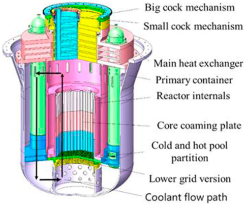
Figure 1. Schematic diagram of the LFR structure.
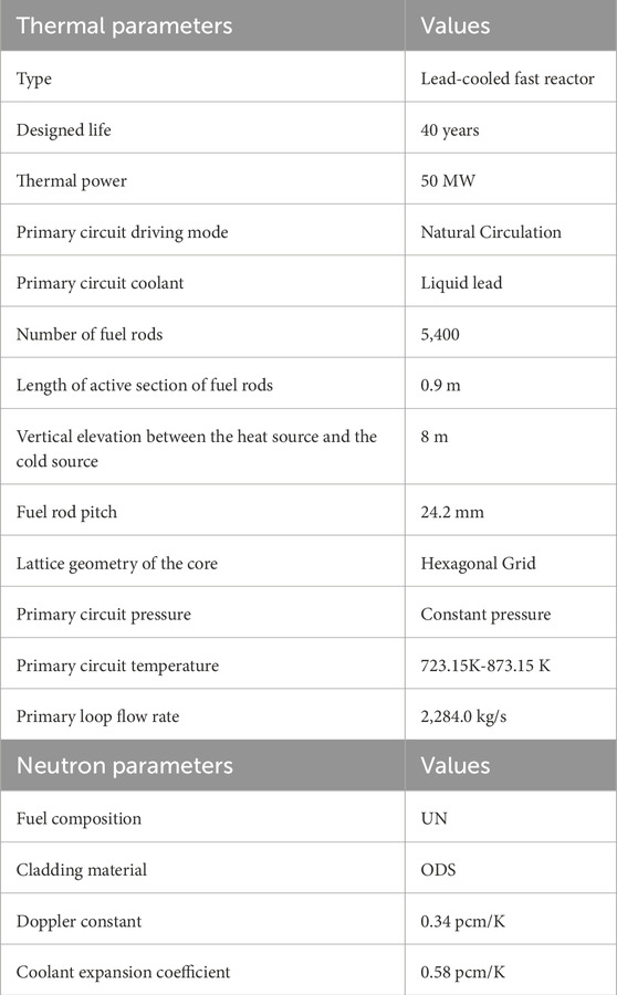
Table 1. Design parameters of LFR.
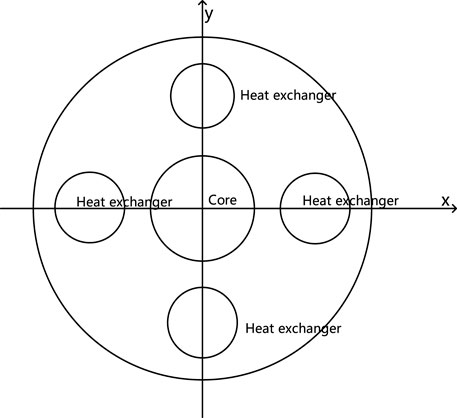
Figure 2. Schematic diagram of heat exchangers configurations in reactor.
Due to the vertical elevation between the reactor core and the heat exchangers was identical in the land environment, the heat exchangers configurations did not affect the thermal-hydraulic characteristics of the reactor primary loop. However, when the reactor was operating in the marine environment, the vertical elevation between the heat source and the cold source was different under inclined conditions. Therefore, the impact of heat exchangers configurations on the thermal-hydraulic characteristics of the natural circulation LFR under inclined conditions should have been considered. The heat exchangers in the reactor were initially arranged such that adjacent heat exchangers were separated by 90°. The angle between the heat exchanger and the central axis of floating nuclear power plant is θ, the heat exchangers configuration could be systematically modified, resulting in distinct heat exchangers configuration as θ increased. The results that θ = 0° and θ = 45° are shown in the Figure 3 below.

Figure 3. Schematic diagram of heat exchanger configuration. (a) θ = 0° (b) θ = 45°.
3 Simulation model
3.1 Physical properties model of lead coolant
In 2007, the International Energy Agency published a handbook on lead and liquid lead alloys based on previous liquid metal research (OECD, 2015), which fully described the physical properties of lead and liquid lead. In this study, the physical properties of liquid lead were modified on the basis of the original RELAP5 physical properties modification. The physical parameters that were applied to calculate the properties of liquid lead coolant in the program were shown in Table 2, including melting point, boiling point, density, thermal conductivity, specific heat capacity, dynamic viscosity, and thermal expansion coefficient.
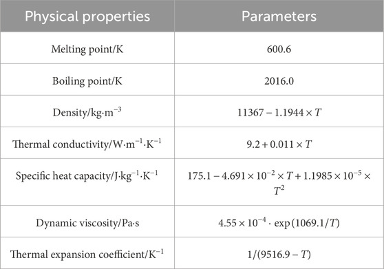
Table 2. Physical properties of lead coolant.
3.2 Fluid flow and heat properties model of lead coolant
In this study, the models of extended heat transfer required for liquid lead metal fluid were added in the RELAP5 program (Liu et al., 2024a), including the heat transfer models for circular tubes and rod bundles. Through extensive research and analysis by scholars, the heat transfer model for liquid metal circular tubes recommended by Seban agreed well with the experimental results (The RELAP5-3D Code Development Team, 1995), and the simplified heat transfer model for rod bundles by Ushakov matched the experimental data well (Borishanski et al., 1979). The circular tube heat transfer model and rod bundle heat transfer model are as Equations 1, 2:
Circular tube heat transfer model:
Rod bundle heat transfer model:
In the formula:
The RELAP5 program was unable to calculate the friction resistance coefficient based on the type of flow channel. However, the flow characteristics of lead-cooled coolant in the rod bundle area were significantly different from those of water. Therefore, this study adopted the modified Rehme model by scholars from abroad to calculate the friction resistance coefficient (Waltar et al., 2012). The modified Rehme model is as Equations 3, 4:
In the formula:
3.3 RELAP5 thermal-hydraulic model
The RELAP5 software was a comprehensive software designed to simulate the thermodynamic processes within a reactor, including coolant flow, heat transfer, and pressure variation. The software employed a staggered grid method to simulate heat transfer between thermal-hydraulic components and established the conservation equations for coolant mass, momentum, and energy, to simulate coolant flow, heat transfer, and pressure variation within the reactor. The mass conservation equation is as Equation 5:
In the formula:
The momentum conservation equation is as Equation 6:
In the formula:
The energy conservation equation is as Equation 7:
n the formula:
The main function of the natural circulation LFR primary loop was to transfer heat from the core to the secondary loop through the liquid lead coolant. The coolant flowed from the core into the hot pool, then flowed to four heat exchangers spaced at 90° with each other, and finally flowed into the cold pool, then returned to the core. To simplify the analytical calculation, the following assumptions were made:
(1) Point kinetics model was employed to simulate the neutronics.
(2) The one-dimensional analysis model was adopted, ignoring the radial distribution of the coolant, with the coolant flowing along the direction of the pipeline.
(3) All pipe sections, except for the heating and cooling sections, were uniformly treated as adiabatic.
(4) The inclined condition was introduced instantaneously, with the range of the inclination angle being 0°–30°.
The RELAP5 software was employed to establish a flow and heat transfer simulation model of the reactor, and the natural circulation LFR primary loop was simplified. The core, the primary loop, and the secondary loop sides of the main heat exchangers were simplified into a direct current channel, and the flow area and heat transfer area remained unchanged after the simplification. The thermal-hydraulic analysis model of the reactor was shown in Figure 4. The 120, 121, and 122 represented the core hot channel, average channel, and side flow channel respectively. The 151, 152, 153, and 154 simulated the heat exchangers’ primary loop coolant side, while the 220, 320, 420, and 520 simulated the heat exchangers’ secondary loop side. The 200, 300, 400, and 500 were simulated as the coolant supply boundary of the second loop. The point kinetic model was employed to the heat source, and the heat transfer structures were set up between the pipe models on both sides of the heat exchangers. It was used to simulate the flow and heat transfer process of primary coolant in LFR and to construct the simulation model of the primary loop in LFR. The coolant flow pipes 151, 152, 153, and 154 on the primary loop side of the heat exchanger were named as channels 1, 2, 3, and 4, which were used to compare the differences in the thermal-hydraulic characteristics of different heat exchanger flow channels under inclined conditions.
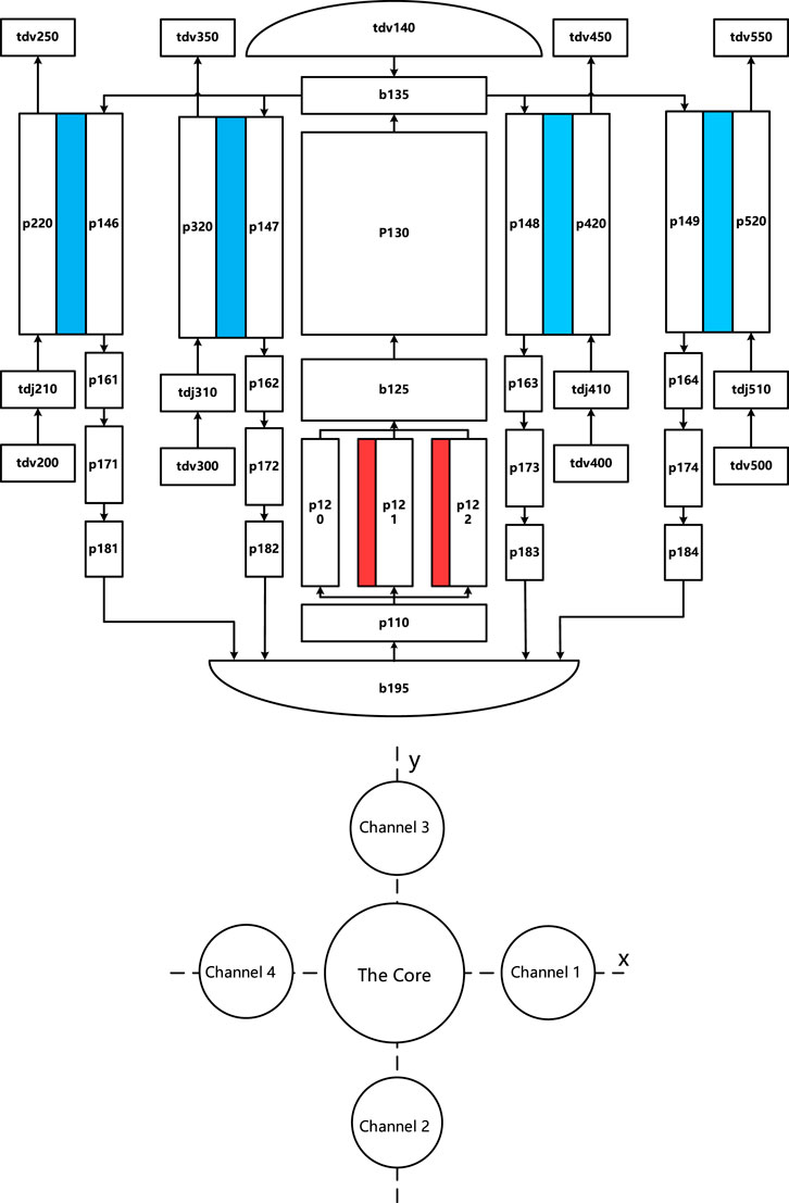
Figure 4. RELAP5 node diagram of LFR.
Based on the RELAP5 thermal-hydraulic analysis model, natural circulation LFR was simulated at 100% FP power. As shown in Table 3, the relative error of core power, core flow rate, and core inlet and outlet temperature was less than 2% between the design value and the calculation value. This proved that the RELAP5 thermal-hydraulic analysis model was accurate and could be used for further thermal-hydraulic safety analysis of natural circulation LFR under inclined conditions.
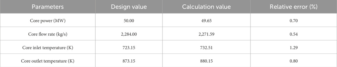
Table 3. Simulation and comparison of steady-state condition.
3.4 Simulation of inclined condition
This study defined two physical parameters: inclination angle (α) and angle (θ) between the heat exchanger and the central axis of floating nuclear power plant, and the specific inclined condition of the reactor could be accurately represented with them. The natural circulation LFR was shown in Figure 5. It was assumed that the core geometry center was simplified to one heat source and the geometric centers of four heat exchangers were simplified to four cold sources, and the core channel was simplified to the central axis of the reactor. When the reactor was not under inclination condition, all the vertical elevation between the four heat exchangers centers and the core center was equal to H, and the spacing between the heat source and the cold sources was L. While the reactor was inclined along the heat exchanger and rotated clockwise around this central axis, the vertical elevation between the heat source and the cold sources of channel 1, 2, 3, and 4 changed to H1, H2, H3, H and H4, α was the inclination angle and θ was the angle between the heat exchanger and the central axis of floating nuclear power plant is θ.
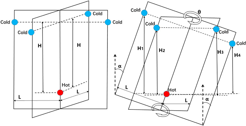
Figure 5. Schematic diagram of inclined condition.
When the reactor operates in a natural circulation state, the natural circulation driving force was equal to the flow resistance, the natural circulation driving force equation is as Equations 8, 9:
In the formula:
The natural circulation driving force was mainly affected by vertical elevation between the heat source and the cold source. The natural circulation driving force of the reactor under inclined conditions is as Equation 10:
The geometry parameters of the reactor under inclined condition were entered into the RELAP5 restart card to simulate the thermal-hydraulic characteristics of the reactor under inclined condition.
According to Nuclear-Ship Code of safety for nuclear merchant ships Section (IMO, 1981), the reactor safety was designed to operate safely when the ship experienced the 0°–30° inclination angle within these limits. Therefore, the 0°–45° angle between the heat exchanger and the central axis of floating nuclear power plant could be used to reflect the heat exchangers configurations under inclination condition, due to the heat exchangers being arranged symmetrically.
4 Results and discussion
4.1 Reactor 100% FP power stable operating condition
The study assumed that the reactor was at 100%FP power condition, which was inclined at a 15° angle along heat exchanger coolant channel 1 at 100 s. As illustrated in Table 4 below, the flow rates in channels 2 and 4 decreased slightly, while the flow rate in channel 1 decreased substantially, and the flow rate in channel 3 increased. Overall, the core flow rate exhibited a downward trend, decreasing by 1.20% compared to that under 100% FP power conditions. On the inclined side, the decrease of vertical elevation between the heat source and cold source reduced coolant flow through the inclined channel, while the increase of vertical elevation between the heat source and cold source increased coolant flow through the opposite channel, which led to significant alterations in the core flow rate.
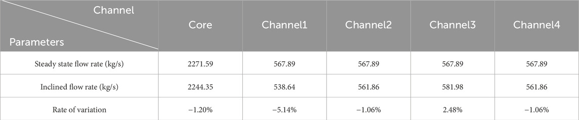
Table 4. Core and each coolant channels of heat exchangers flow rate.
The variations in reactor core flow rate under inclination angles ranging from 5° to 30° were summarized in Table 5. With the increase of inclination angle, the core flow rate decreased significantly. When the inclination angle was 30°, the reactor core flow rate decreased to 95.12% of the core flow rate at 100% FP power, and a positive correlation was observed between the inclination angle and the magnitude of core flow rate reduction. Concurrently, the decrease of core flow rate led to corresponding increases in both the core outlet temperature and core cladding temperature, with increments of 4.15K and 5.90K, respectively. Notably, when the inclination angle under the maximum inclination angle, the core cladding temperature remained below the design safety limit for cladding temperature of 973.0K, which proved that the reactor could operate safely under inclined condition. The results showed that larger inclination angles exacerbated thermal-hydraulic challenges, so the compact core configuration of heat exchangers was implemented to reduce the influence of the inclined condition on reactor safety.
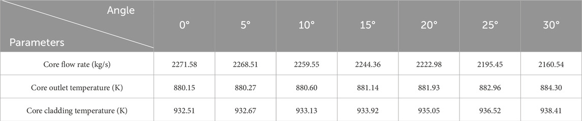
Table 5. Core flow rate, outlet and cladding temperature at different inclination angle.
When the reactor was operating under inclined condition, the flow rate distribution of the heat exchanger coolant channels was not uniform, due to the differential elevation between core and heat exchangers. As illustrated in Figure 6, the variations of coolant flow rates and outlet temperatures in the four heat exchanger channels under varying inclination angles (0°–30°) were quantified. When the inclination angle was 30°, the flow rate of channel 3 increased by 3.16%, the flow rate of channel 1 decreased by 14.07%, and the flow rates of channels 2 and 4 both decreased by 4.32%. The decrease of core flow rate in channel 1 extended the residence time of the coolant and raised the outlet temperature, while the increase of core flow rate in channels 2-4 shortened the residence time and lowered the outlet temperature. Thus, the temperature difference between channel 1 and channel 4 increase to 2.42K at 30° inclination angle. With the increase of angle between the heat exchanger and the central axis of floating nuclear power plant, the trend of maximum difference variation between the flow rates of each heat exchanger gradually slowed down, and the variation of outlet temperature difference of the heat exchanger also reduced.
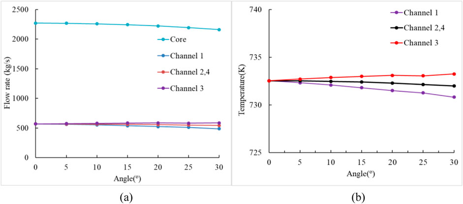
Figure 6. Core and each coolant channels of heat exchangers flow rate and outlet temperature. (a) Flow rate (b) Outlet temperature.
When the reactor operated at 100% FP power, which was inclined along the heat exchanger coolant channel 1 at fixed angles of 10°, 20°, and 30°, it then rotated clockwise around the central axis with angles between the heat exchanger and the central axis of floating nuclear power plant of 0°, 7.5°, 15°, 22.5°, 30°, 37.5°, and 45°. Despite the invariance of core flow rate, the angle between the heat exchanger and the central axis of floating nuclear power plant significantly influenced thermal-hydraulic parameters in the heat exchanger coolant channels. As shown in Figure 7, the increase of angle between the heat exchanger and the central axis of floating nuclear power plant affected flow rate in channels 1 and 2, while flow rates in channels 3 and 4 decreased. When the angle between the heat exchanger and the central axis of floating nuclear power plant was 45°, channels 1 and 4, as well as channels 2 and 3 achieved equivalent flow rates. At 10°, 20°, and 30° inclination angles, the maximum flow rate differences between channels decreased by 8.51 kg/s, 17.80 kg/s, 27.87 kg/s, respectively. The results confirmed that the increase of angle between the heat exchanger and the central axis of floating nuclear power plant,which reduced the flow rate distribution of the heat exchanger coolant channel, with larger inclination angles exhibiting a stronger distribution among channels.
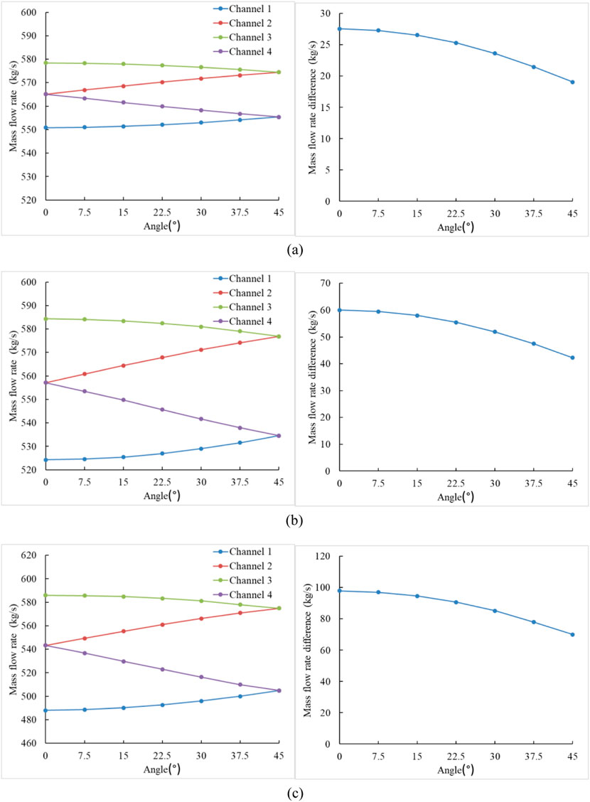
Figure 7. Flow rate and maximum flow rate difference in each heat exchangers coolant channels. (a) Flow rate and maximum flow rate difference in each heat exchanger coolant channels at the inclination angle of 10° (b) Flow rate and maximum flow rate difference in each heat exchanger coolant channels at the inclination angle of 20° (c) Flow rate and maximum flow rate difference in each heat exchanger coolant channels at the inclination angle of 30°.
The outlet temperatures of heat exchanger coolant channels exhibited a direct dependence on flow rate variation. As shown in Figure 8, outlet temperatures in channels 1 and 2 increase, while outlet temperatures in channels 3 and 4 experienced a temperature reduction. When the angle between the heat exchanger and the central axis of floating nuclear power plant was 45°, channels 1 and 4, as well as channels 2 and 3, achieved equivalent outlet temperatures. At 10°, 20°, and 30° inclination angles, the maximum outlet temperature differences between channels decreased by 0.23K, 0.46K, 0.66K, respectively. The angle between the heat exchanger and the central axis of floating nuclear power plant is θ. When the angle between the heat exchanger and the central axis of floating nuclear power plant is 45°, the reactor had a slighter outlet temperature difference between the outlets of the heat exchanger coolant channels. It minimized localized hot spots and stabilized coolant residence time distribution, so it showed more superior performance in terms of thermal-hydraulic reactor safety.
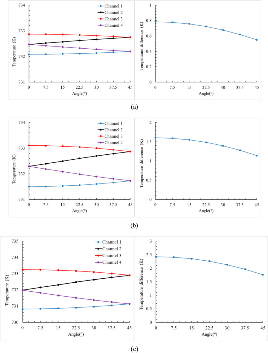
Figure 8. Outlet temperature and maximum outlet temperature difference of each heat exchangers coolant channels. (a) Outlet temperature and maximum outlet temperature difference of the heat exchanger coolant channels at the inclination angle of 10° (b) Outlet temperature and maximum outlet temperature difference of the heat exchanger coolant channels at the inclination angle of 20° (c) Outlet temperature and maximum outlet temperature difference of the heat exchanger coolant channels at the inclination angle of 30°.
4.2 Reactor power increasing and decreasing conditions
This study simulated reactor during the process of power increasing and decreasing under inclined conditions, assuming initial operation at 100% FP power, and analyzed the thermal-hydraulic safety characteristics of the reactor under these conditions. At 100s, the reactor inclined to 10°, 20°, and 30° along the heat exchanger coolant channel 1, and negative reactivity was introduced with control rod insertion to initiate reactor decreasing. The power reduction rate decelerated as power approached 30 MW at 1,300s, and the power reduced to 30 MW at 2,500s due to temperature negative feedback. This process of reactor power decreasing spanned 2,400s, equivalent to a decrease rate of 1% FP/min. At 10,000s, positive reactivity was introduced with control rod lifting to initiate reactor power increasing. The core power was slightly below 50MW, and the increase rate of power slowed down at 11,200s; then the power reached 50 MW at 12,400s. During the process of power increasing and decreasing under inclined conditions, the larger inclination angle resulted in a higher coolant temperature. Under identical reactivity and inclination angle conditions, the variation of core flow rate lagged behind the variation of core power, resulting in the increase in both the core outlet temperature and the core cladding temperature. Figure 9 illustrated the variations in core flow rate, outlet temperature, and core cladding temperature during reactor power increasing and decreasing. Due to the introduction of the 30° inclination angle at 100s, the core flow rate immediately and rapidly decreased, then synchronized with the decreased rate of 1% FP/min power. During the periods from 100s to 1,200s and from 11,200s to 12,400s, the variation of flow rate lagged behind the variation of power, with reactor stability restored through the reestablishment of natural circulation from 3,700s to 13,600s as the rate of power increasing and decreasing stabilized. When the inclination angle was 30°, the core flow rate reached a minimum of 1,842.07 kg/s at 60%FP power, while it reached 2,160.54 kg/s at 100%FP power. The variation of thermal characteristics exhibited a dynamic coupling behavior in response to the variation of flow rate, with the core outlet temperature and core cladding temperature reaching maximum values of 884.3K and 938.42K, respectively.
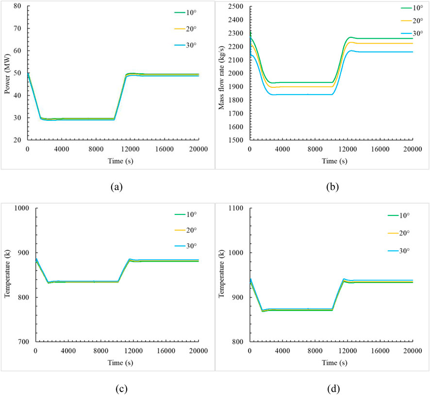
Figure 9. Core power, flow rate, outlet and cladding temperature at different inclination angle. (a) Core power (b) Core flow rate (c) Core outlet temperature (d) Core cladding temperature.
The simulation initialized the reactor operating steadily at 100% FP full power. At 100 s, the reactor instantaneously inclined to 30° along the heat exchanger coolant channel 1 and introduced negative reactivity by inserting the control rods into the core at varying speeds. During the periods from 100s to 4,900s, power decrease rates of 1% FP/min, 0.75% FP/min, and 0.5% FP/min were implemented, achieving transitions from 50 MW to 30 MW over durations of 2,400s, 3,600s, and 4,800s, respectively, with steady 30 MW operation attained at 2,500s, 3,700s, and 4,900s. Subsequently, during the periods from 10,000s to 14,800s, positive reactivity was introduced by lifting the control rods into the core at identical rates, restoring power from 30 MW to 50 MW over equivalent durations of 2,400s, 3,600s, and 4,800s, ultimately reestablishing 100% FP power at 12,400s, 13,600s, and 14,800s. The results showed that the steady-state power derivative remained constant regardless of the power increasing and decreasing rate. Figure 10 illustrated the variations in core flow rate, outlet temperature, and cladding temperature during reactor power increasing and decreasing. Due to the introduction of the 30° inclination angle at 100s, the core flow rate immediately and rapidly decreased, then synchronized with the reduction of 1%FP/min, 0.75FP%/min, 0.5FP%/min. During power decreasing, the reactors re-established natural circulation and stabilized at 3700s, 4900s, and 6100s, respectively. Conversely, during power rising, stabilization occurs at 13,600s, 14,800s, and 16,000s, respectively. The result showed that decreased and increased rate of reactor power delayed scale inversely with the rate of power variation, the time to restore stability demonstrated 2400s between fastest rate at 1%FP/min and slowest rate at 0.5%FP/min, revealed the response characteristic of reactor power increasing and decreasing to the establishment of the natural circulation.
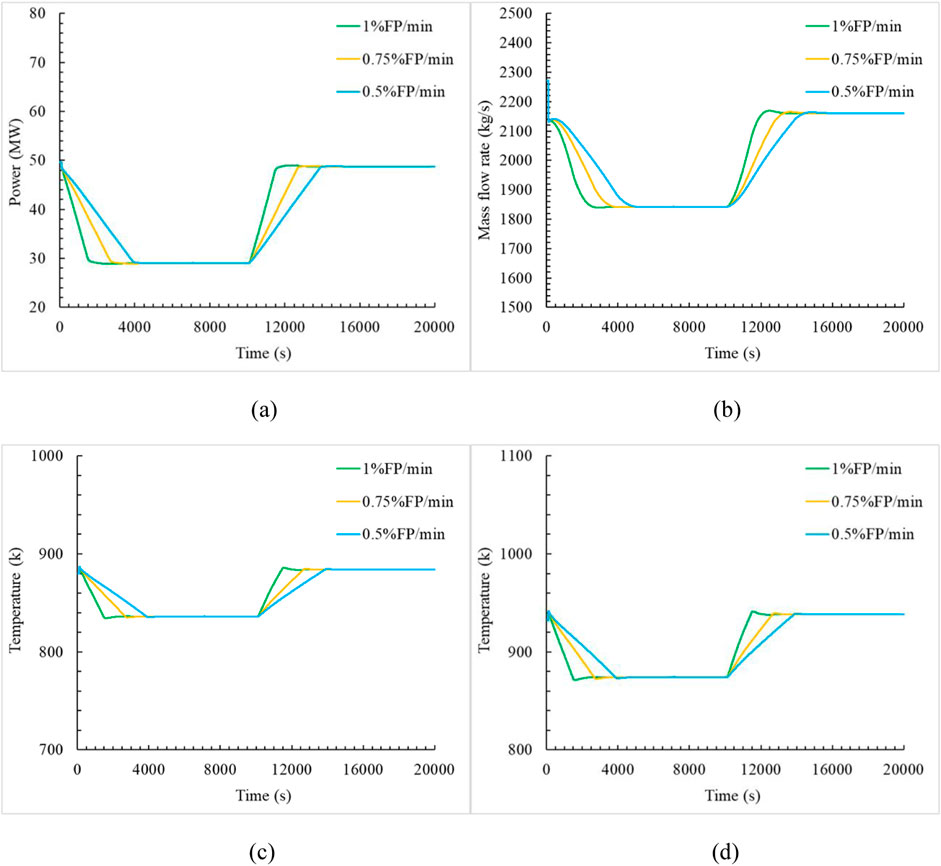
Figure 10. Core power, flow rate, core outlet and cladding temperature at different power increase and decrease rates. (a) Core power (b) Core flow rate (c) Core outlet temperature (d) Core cladding temperature.
5 Conclusion
This study employed RELAP5 software to analyze the impact of inclination angle and heat exchangers configuration on the thermal-hydraulic characteristics of the reactor and evaluated the safety performance of the natural circulation LFR under inclined condition.
(1) When the reactor was under inclined condition, the core flow rate decreased with the increase of reactor inclination angle. As the inclination angle became larger, the trend of core flow rate decline became more obvious. When the inclination angle was 30°, the reactor core flow rate reduced to 95.12% of the flow rate at 100%FP power, the core cladding temperature increased by 5.90K, and the maximum temperature difference between heat exchangers increased by 2.42K. Therefore, the inclination angle should have been reduced as much as possible to lessen the impact on the thermal-hydraulic safety characteristics of LFR.
(2) With the increase of the angle between the heat exchanger and the central axis of floating nuclear power plant, the maximum outlet temperature difference between the heat exchanger coolant channels gradually decreased. When the angle between the heat exchanger and the central axis of floating nuclear power plant is 45°, the reactor had a slighter outlet temperature difference between the outlets of the heat exchanger coolant channels. When the inclination angle was 10°, 20°, and 30°, the maximum flow rate difference between the heat exchanger coolant channels reduced to 8.51 kg/s, 17.80 kg/s, 27.87 kg/s respectively, and the maximum outlet temperature difference of the heat exchangers was reduced to 0.23K, 0.46K, 0.66K. The angle between the heat exchanger and the central axis of floating nuclear power plant is 45°, which exhibited better performance in the thermal-hydraulic safety of the primary loop. To reduce the impact of inclined condition, in terms of reactor design, the angle between the heat exchanger and the central axis of floating nuclear power plant should be arranged in 45°.
(3) When the reactor experiences during the process of power increasing and decreasing, the impact of inclination on reactor performance became more pronounced with the increase of reactor power. Specifically, under inclined conditions, higher power led to a more substantial reduction in core flow rate and an increase in core cladding temperature. When the reactor power rose at 0.5%FP/min and the inclination angle was 30°, the reactor power reached 50 MW at 14800s, and the core cladding temperature also were increased to 938.42K, which proved that the reactor exhibited a strong thermal-hydraulic safety margin.
The study provided a technical reference for the practical application of natural circulation lead-cooled fast reactors in marine environments and held important academic and engineering application value for future research on floating nuclear power plant reactors.
Data availability statement
The raw data supporting the conclusions of this article will be made available by the authors, without undue reservation.
Author contributions
JL: Methodology, Software, Writing – original draft. TL: Project administration, Supervision, Writing – review and editing. YL: Project administration, Writing – review and editing. DZ: Project administration, Writing – review and editing. DY: Project administration, Writing – review and editing.
Funding
The author(s) declare that financial support was received for the research and/or publication of this article. The current work is supported by the Natural Science Foundation of Chongqing (2023NSCQ-BSX0026), Taishan Scholars Program (TSTP20231246), the Natural Science Foundation of Shandong (ZR2024QE271) and Nuclear Technology Innovation Joint Fund of National Natural Science Foundation of China (U1967204). We thank the great help from other members of FDS Consortium.
Conflict of interest
Authors TL, YL, DZ, and DY were employed by Institute of Neutron Energy Co. Ltd.
The remaining author declares that the research was conducted in the absence of any commercial or financial relationships that could be construed as a potential conflict of interest.
Generative AI statement
The author(s) declare that no Generative AI was used in the creation of this manuscript.
Publisher’s note
All claims expressed in this article are solely those of the authors and do not necessarily represent those of their affiliated organizations, or those of the publisher, the editors and the reviewers. Any product that may be evaluated in this article, or claim that may be made by its manufacturer, is not guaranteed or endorsed by the publisher.
References
Borishanski, Y. M., Gotovskii, M. A., and Firsova, E. V. (1979). Heat transfer to liquid metals in longitudinally wetted bundles of rods. Sov. At. Energy 27 (6), 1347–1350. doi:10.1007/bf01118660
IMO (1981). Nuclear-Ship Code of safety for nuclear merchant ships. Available online at: https://puc.overheid.nl/nsi/doc/PUC_3002_14/1/.
Ishida, T., Kusunoki, T., Ochiai, M., Yao, T., and Inoue, K. (1995). Effects by sea wave on thermal hydraulics of marine reactor system. J. Nucl. Sci. Technol. 32 (8), 740–751. doi:10.3327/jnst.32.740
Iyori, I., Aya, I., Murata, H., Kobayashi, M., and Nariai, H. (1987). Natural circulation of integrated-type marine reactor at inclined attitude. Nucl. Eng. Des. 99, 423–430. doi:10.1016/0029-5493(87)90138-5
Kim, J. H., Kim, T. W., Lee, S. M., and Park, G. C. (2001). Study on the natural circulation characteristics of the integral type reactor for vertical and inclined conditions. Nucl. Eng.Des. 207, 21–31. doi:10.1016/s0029-5493(00)00417-9
Ko, Y., Seo, H., Cho, H., and Yi, K. (2024). Effect of inclination on SB LOCA transient of a floating nuclear reactor in MARS-KS analysis using moving reactor model. Nucl. Eng. Des. 426, 113407. doi:10.1016/j.nucengdes.2024.113407
Kurosawa, A., and Fujiie, Y. (1967). Two phase flow behavior induced by ship's motion. J. Nucl. Sci. Technol. 11 (4), 584–586. doi:10.1080/18811248.1967.9732811
Li, W., Liu, J., Bai, Y., Li, Y., Jin, M., Li, T., et al. (2024). Design and analysis of a direct reactor auxiliary cooling system for a pool-type small modular lead-based reactor. Ann. Nucl. Energy 207, 110678. doi:10.1016/j.anucene.2024.110678
Liu, W., Wang, L., Zhou, T., Zhang, G., and Bai, Y. (2019). Transient characteristics analysis of lead-based reactor from forced circulation to natural circulation. Prog. Nucl. Energy 117, 103052. doi:10.1016/j.pnucene.2019.103052
Liu, Z., Liu, L., Guo, Z., Guo, H., Cong, T., Liu, M., et al. (2024a). Numerical simulation of the ocean conditions impact on heat pipe-cooled molten salt reactor core thermal-hydraulic performance. Nucl. Eng. Des. 421, 113066. doi:10.1016/j.nucengdes.2024.113066
Liu, Z., Tian, W., Wang, C., Zhang, D., Zhang, K., Qiu, S., et al. (2024b). Experimental study of the influence of buoyancy on turbulent mixed convection in lead–bismuth eutectic flow under inclined conditions. App. ng. 244, 122694.
OECD (2015). Handbook on lead-bismuth eutectic alloy and lead properties, materials compatibility. Thermal-hydraulics Technol.
The RELAP5-3D Code Development Team. (1995). RELAPs-3D code manual volume IV: models and correlations. INEEL-EXT-98-00834.
Wang, L., Wu, G., Wang, J., Jin, M., and Song, Y. (2018). Numerical investigation of the core outlet temperature fluctuation for the lead-based reactor. Ann. Nucl. Energy. 117, 194–201. doi:10.1016/j.anucene.2018.03.020
Wu, G., Li, Y., Wang, M., and Chen, Y. (2018). Design and performance analysis of passive residual heat removal system for a lead-cooled fast reactor. Prog. Nucl. Energy 103, 236–242. doi:10.1016/j.pnucene.2017.11.018
Wu, Y., Bai, Y., Song, Y., Huang, Q., Zhao, Z., and Hu, L. (2016). Development strategy and conceptual design of China lead-based research reactor. Ann. Nucl. Energy. 87, 511–516. doi:10.1016/j.anucene.2015.08.015
Wu, Y. (2016). Design and R&D Progress of China Lead-Based Reactor for ADS Research Facility[J]. Eng. 2, 124–131.
Keywords: lead-cooled fast reactor, natural circulation, inclined condition, RELAP5, thermal-hydraulic safety characteristics
Citation: Liu J, Li T, Li Y, Zhou D and Yu D (2025) Thermal hydraulic safety characteristics analysis for the natural circulation primary loop under inclined condition on LFR. Front. Energy Res. 13:1566271. doi: 10.3389/fenrg.2025.1566271
Received: 24 January 2025; Accepted: 11 April 2025;
Published: 02 May 2025.
Edited by:
Shichang Liu, North China Electric Power University, ChinaReviewed by:
Abdus Sattar Mollah, Military Institute of Science and Technology (MIST), BangladeshPengcheng Zhao, University of South China, China
Yang Liu, Lanzhou University of Technology, China
Guangchun Zhang, Harbin Institute of Technology, China
Copyright © 2025 Liu, Li, Li, Zhou and Yu. This is an open-access article distributed under the terms of the Creative Commons Attribution License (CC BY). The use, distribution or reproduction in other forums is permitted, provided the original author(s) and the copyright owner(s) are credited and that the original publication in this journal is cited, in accordance with accepted academic practice. No use, distribution or reproduction is permitted which does not comply with these terms.
*Correspondence: Tingyu Li, dGluZ3l1LmxpQGZkcy5vcmcuY24=