 Zheng Yang1,2
 Yabo Cao
- 1Hebei Key Laboratory of Distributed Energy Storage and Microgrid, North China Electric Power University, Baoding, China
- 2State Grid Jibei Integrated Energy Service Co., Ltd., Beijing, China
Various controllable resources contribute to energy regulation and rapid support in the form of virtual energy storage (VES), which can significantly simplify control parameters and facilitate the evaluation of a microgrid’s economic and secure operational reserves. This paper establishes a power density virtual energy storage (PDVES) model and an energy density virtual energy storage (EDVES) model. Wind turbines, photovoltaics (PVs), controllable loads, and electric vehicles (EVs) are equated to EDVES and PDVES, respectively. Furthermore, an economic calculation model for microgrids that incorporates VES is developed, and an energy regulation framework for microgrids is constructed with virtual current (VCU) and virtual capacitor (VCA) as scheduling parameters. With the frequency security of island microgrids as a constraint, a rapid support coordinated control strategy for PDVES and EDVES is proposed to ensure the economic and secure operation of microgrids across multiple time scales. Finally, a high-proportion renewable energy test system with VES is established. The test results demonstrate that under the proposed VES control, the energy regulation and dynamic stability control performance of microgrids can be significantly improved.
1 Introduction
With the rapid increase in the proportion of distributed wind power, photovoltaic (PV), electric vehicles (EVs), seawater desalination loads (SDLs), and other flexible resources (FRs) connected to the power system, both the power supply and load sides present a power challenge potential (Thomas et al., 2018). Microgrids are in urgent need of a feasible solution in order for new energy and controllable loads to be integrated into the system’s energy regulation and rapid support control system, realizing the collaborative participation of power sources and loads in system regulation (Mateus et al., 2025; Lin et al., 2025). However, the power output of wind power and PV on the power supply side is intermittent, and controllable loads such as EVs and SDLs have heterogeneous control parameters. Due to the complexity of the operating parameters, microgrids lack a means of evaluation for the system energy and dynamic stability reserves, which not only makes it difficult to optimize economic operation but also makes it hard to cope with disturbances and guarantee the safe operation of the system. Therefore, microgrids need to integrate FRs, simplify operating parameters, and collaborate to accomplish energy regulation and rapid support control objectives, which will be key to improving the economic and safe operation of the system.
Enhancing the economy of microgrid operation through the cooperative operation of new energy sources, energy storage, and loads is a key research direction for microgrids. Multilevel optimal scheduling models of microgrids have been constructed, which provide a feasible solution for optimizing the energy regulation mode of power source, load and energy storage (Huang et al., 2024; Cao et al., 2025; Li et al., 2025; Morais et al., 2012; Sun et al., 2023) Yang et al. (2025), and Shui et al. (2024) assembled air conditioners, EVs, and smart buildings in a microgrid; considered the interest demands of power, load, and energy storage; and proposed a master–slave co-optimization method to save system investment costs by reducing the peak–valley difference of the operation of the microgrid. However, while the introduction of a demand-side response in microgrids is beneficial for increasing revenue, there is still a lack of coordinated methods for controllable loads, and the resource flexibility potential needs to be further developed. Simplifying system operating parameters reduces the difficulty of energy regulation and coordination between the power supply and load sides, which is essential for unlocking the regulation potential of various FRs. The VES technology, which equates FRs to energy storage and operates jointly with real energy storage, has become a popular topic of research. For example, on the load side, the energy conversion relationship between FRs such as EVs (Westermann and Schlegel, 2013; Zhu and Zhang, 2025), smart air conditioners (Wang et al., 2021; Pahasa et al., 2022), and SDLs (Zhou et al., 2020; Liu et al., 2021), and energy storage is established, and the controllable load can simulate the charging and discharging characteristics of energy storage. Lv et al. (2024) and Wang et al. (2020) established the dynamic relationship between thermal inertia and the charging and discharging characteristics of the VES for the cold\heat load in buildings and improved the economy of a building’s energy system through the VES to regulate the load’s cold and heat characteristics. However, microgrids that rely solely on a single device for power regulation struggle to meet system energy demands. To further explore the potential of VES, Lv et al. (2024) and Wang et al. (2020) established a combined VES system that incorporated air-conditioning loads and EVs based on their operational characteristics. This system, while balancing the interests of multiple stakeholders, can effectively reduce peak–valley difference, decrease the dependence of the regional power system on traditional energy storage devices, and thus save investment costs. Wang et al. (2024) and Du et al. (2019) proposed realizing the potential of VES by transferring energy across time periods using EVs and smart buildings. By utilizing these in the form of VES, system power fluctuations can be further mitigated. However, due to the different control parameters for electrical and thermal loads, there is still room for improvement in the power coordination between the two. In summary, regarding microgrids, although new energy, energy storage, and load have the potential for energy regulation, the control parameters of each type of equipment are not uniform. Although the charging and discharging characteristics of the VES are involved in system energy regulation, the control process is complicated, and it is difficult to assess the system energy reserve. In microgrids, the joint dispatching strategy of VES and real energy storage needs further improvement.
The rapid responses of FRs to short-term frequency changes to ensure system dynamic stability and alleviate the pressure on power support of the energy storage is another technical bottleneck that urgently needs to be resolved (Chen et al., 2024; Yang et al., 2022). To guarantee the stability of the DC distribution network, Fu et al. (2022) and Tanaka et al. (2011) proposed a coordinated control strategy of controllable loads and batteries to reduce DC voltage fluctuation after disturbances and to avoid the deep charging and discharging of the battery. However, due to the large number of control parameters, the current research does not discuss in detail the control methods for new energy to join the system stability support. Alyami (2024) constructed a hybrid energy storage system containing gas storage, air conditioning, and battery, taking into account time-of-use tariffs, and proposed a coordinated control strategy for PV and hybrid energy storage in an isolated island microgrid. However, while it is suitable for longer time-scale power dispatch, how to respond quickly to short-term frequency changes still needs further research. Gabriele et al. (2023) and Tang et al. (2021) proposed a multi-time-scale coordinated control method for microgrids which can issue control commands for all devices within the day-ahead stage at one time. However, due to the lack of controllable parameters suitable for sensing the power and operating status of controllable devices, the current ability of the microgrid control system to cope with sudden disturbances remains insufficient. In Tangqing et al. (2014) and Honarmand et al. (2014), the energy storage and SDLs coordinate to participate in the primary and secondary frequency regulation of the system. Although existing studies have proposed short-time coordinated control methods for FRs—such as natural gas, smart air conditioners, and SDLs—they have three shortcomings. First, the system power reserve is difficult to assess, and whether the controllable resources can realize continuous regulation needs verification. Second, the operating parameters of the controllable equipment are not uniform, and the design methods of inertia and frequency regulation coefficients are unknown in the short-time frequency response process. Third, whether the FRs in microgrids can take into account energy regulation and short-time frequency support on a long time scale has to be explored. In summary, a VES model urgently needs to be established for microgrids to simplify the operating parameters of each type of FR and to combine the charging and discharging characteristics of PDVES and EDVES. This will realize energy regulation and rapid support control in multiple time scales, give full play to the control potential of the new type of power system, and improve the system operation level.
To optimize the energy regulation effect of microgrids and realize the rapid frequency support control of each type of FR, the PDVES and the EDVES models were respectively established, and a novel cooperative control of VES for energy regulation and rapid frequency support is further proposed. This study is structured as follows. Section 1 establishes VES models for controllable loads, wind turbines (WTs), hydrogen energy storage (HES), and EVs, simplifies the operating parameters of various types of FRs, and proposes the operation mode of a microgrid with VES. Section 2 establishes the economic calculation model of microgrids with VES and proposes a dispatching method of microgrids with VCU and VCA value as unified instructions and VSOC to assess system energy storage. Section 3 proposes a frequency cooperative control adapted to PDVES, EDVES, and real energy storage devices in microgrids, taking into account both the economic and safe operation of microgrids. Section 4 builds a new energy high-proportion test system with multi-type VES and verifies the effectiveness of the proposed control strategies. The study ends with conclusions.
2 Operation mode of microgrids with VES
2.1 PDVES model
In microgrids, distributed energy resources, controllable loads, HES, and EVs can all be considered typical FRs. Distributed energy resources (such as WTs) and controllable loads possess rapid power response characteristics and can be categorized as PDVES devices. EV and HES systems have the capability to provide sustained power support and can be classified as EDVES. Moreover, to ensure the stable operation of microgrids in island mode, the system requires the configuration of a hybrid energy storage system composed of batteries and supercapacitors. In terms of microgrid control structure, the PV units and permanent magnet direct-drive WTs in the distributed energy resources are connected to the microgrid through inverters. The controllable load, exemplified by SDLs, produces fresh water through reverse osmosis. EVs are charged at a constant voltage and slow charging rate and are connected to the microgrid through a bidirectional inverter. HES is integrated into the microgrid through inverters equipped with electrolyzers and fuel cells; it consumes surplus power from the microgrid by producing hydrogen and supplies power to the microgrid by burning hydrogen. The hybrid energy storage system operates in power control mode.
To flexibly regulate various types of FRs in a microgrid, the operational information on distributed energy resources, controllable loads, and other FRs should be collected by the dispatch control center. In addition, hybrid energy storage should rapidly participate in system regulation. The operation mode of a microgrid is depicted in Figure 1. The microgrid’s dispatch center monitors the rotational speed of WTs, the power consumption of controllable loads, and the state-of-charge of EVs, batteries, and supercapacitors. The microgrid needs to process this operational data to generate dispatch commands that facilitate the management and control of multiple types of devices. It also perceives the overall system energy and power reserves, evaluates the reserve status of adjustable system resources, and achieves optimized energy regulation and rapid coordinated control that accounts for various FRs, thereby ensuring the economic operation and dynamic stability of the system.
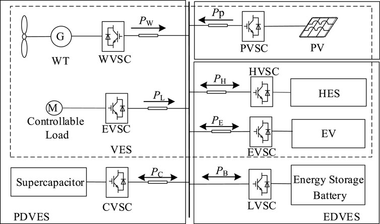
Figure 1. Structure of the microgrid with VES.
To simplify the operational parameters involved in the regulation of FRs in microgrids, this paper will establish models for PDVES represented by new energy sources and controllable loads, as well as EDVES represented by HES and EVs. Through unified scheduling by the microgrid, the complexity of coordinated regulation between FRs and real energy storage devices will be mitigated.
i) Controllable load: SDLs are currently recognized as typical controllable loads in microgrids. The high-pressure pumps in SDLs usually possess variable frequency speed regulation capabilities and can be equated with asynchronous motors for simulation purposes. By mimicking the charging and discharging characteristics of power density supercapacitors, an energy conversion relationship can be established between the energy of the capacitor and the kinetic energy of the rotor in the asynchronous motor. This can be expressed as follows:
where El, Js, ωr, and pn are the rotor kinetic energy, inherent inertia, and angular velocity of the motor, respectively, and Uc is the voltage of the supercapacitor.
It can be seen from Equation 1 that the VCA Cl of the SDL is expressed as
In Equation 2, where ω* r represents the reference value of the electrical angular velocity of the motor.
To facilitate the coordinated control of VES and supercapacitors, this paper introduces the concept of virtual state of charge (VSOC) for the SDL, which is defined as:
In Equation 3, where ωrn represents the rated electrical angular speed of the motor.
ii) Variable speed WT: the variable-speed constant-frequency WT connected to the grid through a power electronic converter has a rapid power response characteristic. The WT simulates the charging and discharging characteristics of a power density supercapacitor, establishing an energy conversion relationship between the capacitor energy and the rotor kinetic energy of the WT. This can be expressed as
It is evident from Equation 4 that after equating the variable-speed WT to VES, the VCA value Cw of the WT can be expressed as
In Equation 5, where ω* opt represents the reference value of the electrical angular speed of the WT rotor.
The VSOC for a variable-speed WT system can be expressed as
In Equation 6, where ωoptn represents the rated value of the electrical angular speed of the WT rotor.
By equating the SDL and the variable-speed WT to VCAs and introducing the VSOC, the microgrid can regulate FRs with rapid power response capabilities. In conjunction with supercapacitors, this facilitates the evaluation of the energy storage and operational status of the VCAs compared to real energy storage, achieving coordinated regulation between distributed energy resources, controllable loads, and supercapacitors.
2.2 EDVES model
i) HES systems exhibit continuous power regulation characteristics during the electricity-to-hydrogen energy conversion process and can participate in power regulation over extended periods. By simulating the charging and discharging characteristics of energy-density batteries, the HES system can establish an equivalent relationship between the hydrogen production process and the battery charging and discharging process, constructing a connection between the energy conversion of battery charging and discharging and the HES system. The rates of hydrogen production via electrolysis and the combustion of hydrogen can be represented respectively as:
In Equation 7, where UEL and UFC represent the input and output voltage of the VES, respectively, IEL and IFC represent the input current and output current of the VES, respectively, ηEL and ηEL represent the electrolysis efficiency and hydrogen combustion efficiency of the HES with values of 0.7 and 0.95, respectively, ηin and ηout represent the power conversion efficiency of the inverter with a value of 0.95, hEL and hFC represent the working states of the electrolysis hydrogen and fuel cell, respectively, and LHVH2 represents the lowest heating value of hydrogen.
After equating the HES device to a virtual battery, the VCU parameter IH2V of the HES can be expressed as:
In Equation 8, where UH2V represents the terminal voltage of the virtual battery.
The VSOC of the HES system, SOCH2(t), can be expressed as follows:
In Equation 9, where MH2max represents the maximum hydrogen mass limit within the hydrogen storage tank.
ii) EVs can adopt time-of-use electricity pricing to guide their charging behavior, achieving orderly load management. By controlling the scaled and orderly charging and discharging of EVs, a controllable virtual battery can be formed to coordinate and solve the problem of unordered charging after EVs are connected to the grid.
EV charging and discharging both occur in a conventionally slow manner. The Monte Carlo simulation method is used to model the daily charging load of EVs. The return time of EVs follows a normal distribution (Zhang et al., 2018) tf ∼ N (17.47, 3.41), and the daily driving distance of EVs follows a log-normal distribution—S ∼ N (3.24, 0.88). Based on the Monte Carlo simulation method and by comparing the return time tf of the ith EV with the end time Tms of the early morning low electricity price period and the start time Tns of the evening peak electricity price period, the VES of EVs can be charged before the end of the early morning low price period to absorb redundant power. After the evening peak price period, the VES of EVs can be discharged to reduce the impact of the original load power. Reasonably arranging the start time Tc for charging the VES of EVs and the start time Td for discharging the VES of EVs is as follows:
In Equations 10, 11, where, Tms represents the end time of the low electricity price period, and Tns represents the start time of the peak electricity price period.
The charging and discharging of the virtual battery require the EV charging pile to obtain the EV battery capacity Ci and the state of charge SOCA I of the battery. The charging pile management system collects EV users’ charging decision behavior, including the expected parking time ti and the desired state of charge level SOCB I when leaving, which is set to 0.8. The charging and discharging duration and the amount of electricity for a single EV are, respectively:
In Equation 12, where, PC is the charging and discharging power of the EV under conventional slow-speed mode, with a value of 1.8 kW, tc is the charging duration of the EV, SOCmin i is the minimum state of charge of the EV, with a value of 0.1, S(i) is the driving distance of the EV, and w is the battery consumption per kilometer of the EV, with a value of 0.15.
The orderly charging and discharging scheduling process of EVs is shown in Figure 2.
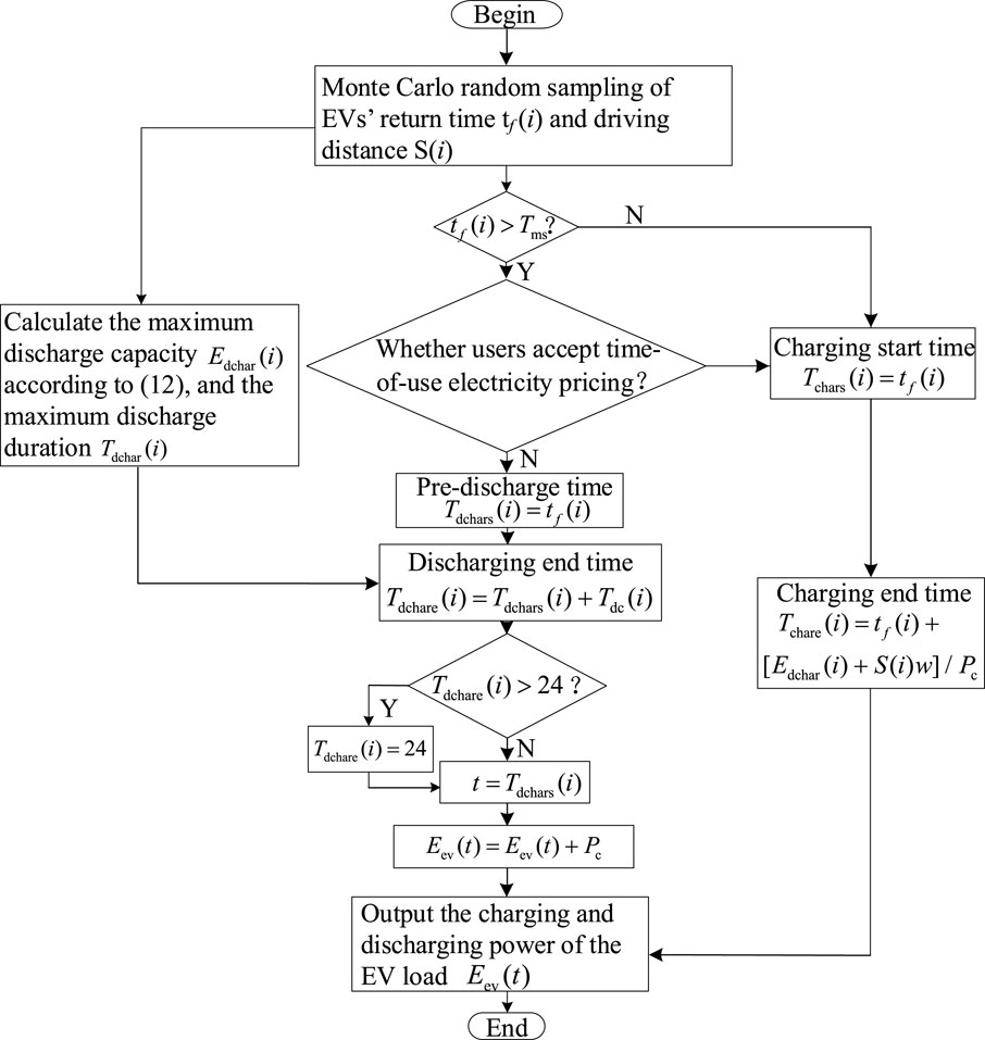
Figure 2. Flowchart of virtual battery emulated by EV.
The entire charging duration of the EV is determined by the discharge amount of its virtual battery and the state of charge at the time of return. By guiding the EV to selectively participate in the energy flow in the microgrid during electricity price valleys and peaks, the start time of the EV’s virtual battery charging and discharging can be expressed thus:
In Equation 13, where Tchare and Tdchare represent the end times of charging and discharging, respectively.
The charging and discharging of the electricity Eev(t) of the EV’s virtual battery at each moment, as determined by Equation 13, can be expressed as follows Equation 14:
After equating the EV to VES, a VCU Iev(t) can be introduced to simulate the battery’s charging and discharging characteristics, which can be expressed as
In Equation 15, where Uev(t) represents the voltage at the busbar of the EV charging station.
The VSOC of the EV can be expressed as
In Equation 16, where ηev represents the charging and discharging efficiency of the EV.
In the microgrid, HES and EVs can introduce VCU and VSOC as control variables, which have the same operating parameters as real batteries and participate in system power regulation, simplifying the control mode of energy density energy storage devices.
3 Cooperative control of VES for energy regulation and frequency support
3.1 Multi-time scale dispatching system of VES
After introducing VES, the multi-time scale scheduling system structure of the microgrid is shown in Figure 3, where the microgrid’s dispatch center is equipped with an energy regulation system for long-time-scale economic optimization operations. After introducing VES, both the EDVES and the battery participate in system regulation and status monitoring through VCU and VSOC, while the PDVES and the supercapacitor participate through VCA and VSOC.

Figure 3. Structure of a multi-time scale dispatching system for microgrids with VES.
In the energy regulation system, the economic optimization model of the microgrid with VES is solved to complete the dispatch command allocation with the goal of reducing economic operation costs. In the short-term rapid support control system, the microgrid prioritizes the use of PDVES devices to provide inertial support at the initial stage of frequency changes, while the EDVES takes on the task of primary frequency regulation. Because VES actively participates in power regulation at different time scales of the system, it not only reduces the capacity of configuring real energy storage devices but also helps reduce the number of charge and discharge cycles of the energy storage devices, thereby extending the service life of those devices.
3.2 Cooperative energy regulation of VES
3.2.1 Objective function
The energy regulation system of the microgrid utilizes the charging and discharging of VES and adjusts the power output of various FRs. The objective function of the microgrid’s energy regulation takes into account the daily revenue R of the load and the operating cost Cmic, and can be expressed as:
In Equation 17, where RH2 represents the revenue from hydrogen production, Rev represents the revenue from EV charging, Rw represents the revenue from the purified water in SDLs, CH2 represents the maintenance cost of HES, Cev represents the compensation cost of EVs, Cwf represents the cost of WTs participating in system regulation, Cwi represents the operation and maintenance cost of WTs, and Chy represents the operation and maintenance cost of energy storage.
3.2.1.1 Revenue of microgrids
As is evident from Equation 17, the revenue of the microgrid is derived from the load revenue, including the revenue from hydrogen production, the revenue from EV charging, and the by-product revenue, which can be expressed as
In Equation 18, where Kfu represents the revenue from products obtained by hydrogen production, ΔSOCH2,TK represents the daily surplus hydrogen mass, ph2 represents the hydrogen selling price, pt(t) represents the electricity purchase price sold by LA to EV users in the time period, Eev(t) represents the charging amount of the virtual battery, Nev represents the number of virtual batteries, and Kl represents the revenue from purified water.
The controllable load participates in power regulation in the form of a VCA. Referring to the speed change of an asynchronous motor, the relationship between the load power PL(t) and the output power of the VCA is can be expressed as Equation 19
Taking the SDL as an example, the relationship between the purified water flow rate and the load output power can be fitted (Wang et al., 2021). The purified water flow rate of the SDL can be expressed as Equation 20
The microgrid scheduling center can output the VCA value according to the revenue optimization result and use the VCA to complete load regulation. The controllable load uses the motor frequency conversion speed regulation system to change the load power so that the PDVES has a variable capacitance value.
3.2.1.2 Cost of microgrids
The operating cost Cmic of the microgrid needs to consider the operation and maintenance cost CH2 of HES, the peak shaving cost Cev of EV users, the regulation cost Cwf of WTs, the operation and maintenance cost Cwi, and the operation and maintenance cost Chy of energy storage, which can be expressed as Equation 21
where, pEL and pFC represent the operation and maintenance costs per unit of electricity of AC and PEMFC, respectively, Km represents the operation and maintenance cost per unit of electricity of WTs, M and Eevd represent the number and discharge amount of virtual batteries, respectively, Δp(t) represents the compensation electricity price per unit of discharge amount of EV connected to the grid, Pwo(t) represents the output power of WTs under maximum power tracking control, Pw(t) represents the output power of WTs under VES control, and Kw represents the unit wind curtailment cost of WTs.
In actual operation, the charging and discharging of the battery will reduce its service life. Therefore, the operation and maintenance cost Chy of the hybrid energy storage includes the operation and maintenance cost Cb and the life loss CB, and can be expressed as Equations 22, 23
where, Khy represents the operation and maintenance cost of energy storage, Phyc(t) and Phyd(t) represent the power output of the energy storage in time period t, respectively, Wtotal represents the purchase cost of the battery, A represents the aging coefficient of the battery, SOHmin represents the critical life of battery scrapping, with a value of 0.8, and SOCB(t) represents the SOC of the battery in time period t.
3.2.2 Constraint conditions
During the microgrid’s operation, it is necessary to ensure the power balance of the power source and the load. Therefore, the power balance constraint of the system can be expressed as Equation 24
To avoid overcharging and over-discharging of the real energy storage device, the state of charge constraints of the supercapacitor and the battery are, respectively, expressed as Equation 25
To ensure the continuous operation of the system during the day, the state of charge at the end of the hybrid energy storage device is constrained to meet the energy regulation needs of the system the next day.
During the operation of the EDVES, the operation limits of the electrical equipment need to be considered. For example, the state of charge constraints of HES and EVs are respectively expressed as Equation 26
The PDVES also needs to consider the allowable operation range of electrical equipment. For controllable loads such as SDLs and WTs, the VSOC constraints can be respectively expressed as
In Equation 27, 46% of the rated speed of the controllable load is set as the minimum rotor speed, which is 1400r/min—the VSOC operation threshold of the controllable load is 21.78%—and 40% of the rated speed of the WT is set as the minimum speed—the VSOC operation threshold of the WT is 16%.
When the HES system is operating, it is necessary to ensure that it works accurately in the AE or PEMFC state. The state constraint of the HES system is expressed as Equation 28
3.3 Cooperative control of VES for frequency support
When the system frequency f remains within the safe range, the microgrid maintains economic operation through the energy regulation system. The system collects the operation states of the VES and the real energy storage device and sends them to the microgrid dispatch control center to complete the long-term scale economic optimization. However, if the microgrid encounters a disturbance and the system frequency exceeds the safe operation range, the microgrid should have the ability to coordinate various FRs to participate in the system frequency regulation and reduce the frequency regulation task of the energy storage. The collaborative operation strategy process of the PDVES and the EDVES in the microgrid is shown in Figure 4.
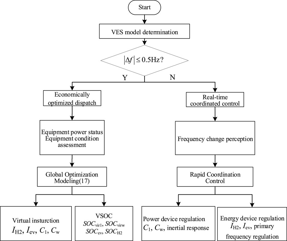
Figure 4. Cooperative control of the microgrid for energy regulation and frequency response.
As seen in Figure 4, within the frequency safety range, the microgrid is in the economic dispatching operation mode. When the frequency exceeds the safe range, the controllable electrical equipment with short-term frequency response in the microgrid includes WTs, controllable loads, EVs, and HES. At this time, the WTs and controllable loads deploy their power rapid response capabilities and provide inertia support in the initial stage of frequency change. EVs and HES participate in the primary frequency regulation of the system.
As shown in Figure 4, the PDVES mainly undertakes the rapid power regulation in the initial inertia response stage (df/dt < 0). In this stage, the PDVES adjusts ω* r and ω* opt respectively through the VCA Cl and Cw to further adjust its power output, share the inertia support task of the supercapacitor, and reduce the rate of change of the system frequency. In the frequency recovery stage (df/dt > 0), the PDVES and the EDVES jointly undertake the frequency regulation task. In this stage, the EDVES outputs IH2 and Iev through the VCU instruction, simulates the charging and discharging characteristics of the battery, adjusts the hydrogen storage electrolysis rate NEL or the hydrogen combustion rate NFC and the EV charging amount Eev(t), respectively, relieves the frequency regulation pressure of the battery, and accelerates the system frequency recovery speed. Under the multi-terminal regulation of the source, storage, and load, the system frequency gradually recovers until (df/dt > 0), when the system frequency returns to the steady-state value, the system frequency no longer changes, an inertia response link exits, and the primary frequency regulation link continues to maintain the safe operation of the system frequency in the new operating state.
In Figure 5, the red lines represent the data flow of the microgrid. The microgrid uses the communication network to obtain information on the output and response of sources, loads, and energy storage. After analysis and processing, this information is converted into coordinated operation commands represented by VCA and VCU parameters. These virtual commands are then transmitted to the FR device terminals through the data flow. The blue lines indicate the power flow of the microgrid, which is the control structure for the FR device to participate in energy regulation. Upon receiving the virtual commands, the FR device terminals switch to the corresponding working modes and adjust the actual parameters. By responding to power changes, they provide rapid frequency support, thereby ensuring the stability of the microgrid operation.
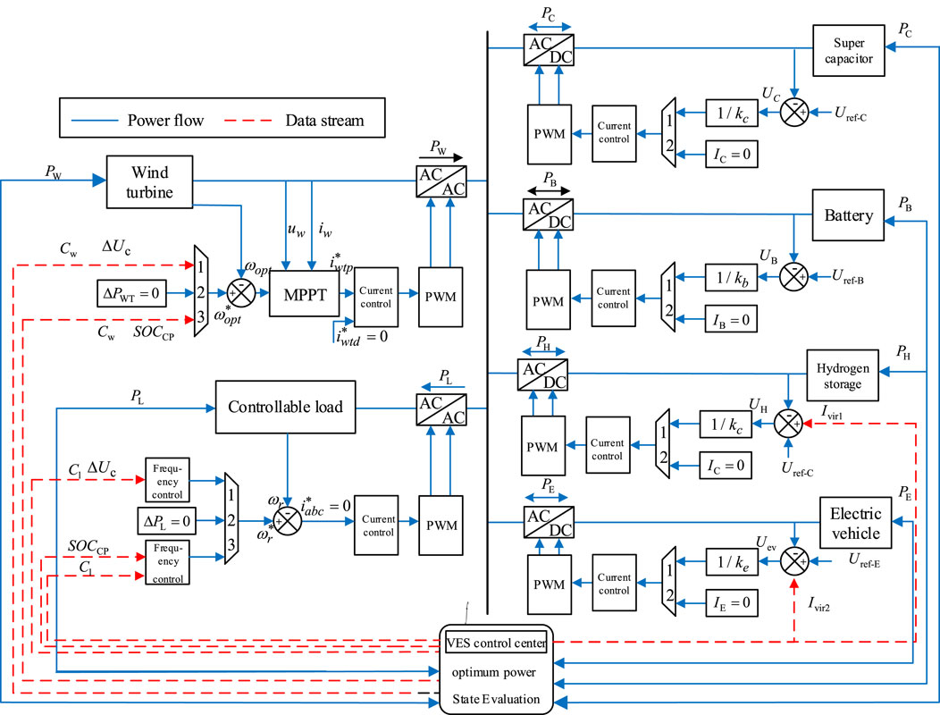
Figure 5. Cooperative control structure diagram of the microgrid with VES.
The VCA value Cvir set by the PDVES has the following relationship with the capacitance value C of the real supercapacitor:
In Equation 29, kvirc represents the VCA adjustment coefficient.
The state of charge of the supercapacitor is closely related to the terminal voltage and can be expressed as
In Equation 30, UC represents the voltage of the supercapacitor, and UCmax and UCmin represent the allowable upper and lower limits of the voltage of the supercapacitor, respectively.
If the system frequency change is Δωe, the PDVES needs to provide inertia support, and the change in virtual rotational kinetic energy is
where, JvB represents the moment of inertia of the PDVES, ωe is the angular velocity of the virtual synchronous generator, and SNB is the capacity of the virtual synchronous generator.
Substituting Equation 32 into Equation 31 yields
In Equation 33,
Writing it in the form of frequency gives
where
Assuming that all the unbalanced energy of the system during the frequency change is provided by the VCA, the energy change of the VCA is expressed as
where Uc and Uc0 are the steady-state DC voltage of the VCA and the voltage value of the VCA after participating in frequency regulation, respectively.
According to Equations 34 and 35, the system frequency change can be reflected as the DC voltage fluctuation of the PDVES so as to adjust the output power of the VCA in Equation 36:
After introducing VES, the relationship between the capacitor voltage and the virtual amplification factor is expressed as
where UC(tset) is the terminal voltage of the capacitor when the set SOCCP value is reached, and UC(tres) is the voltage of the supercapacitor when the SOCCP reaches the limit value.
From Equations 2, 5, and 37, the reference values of the electrical angular velocity of the SDL and the WT are respectively expressed as
In Equations 38, 39, where, K1 = 2pn2UCC1(UCmax-UCmin)/(Jsωm2), ΔSOC = SOCCP-SOCCres; SOCCres represents the limit value of the VSOC SOCCP of the SDL, K2 = UCCw(UCmax-UCmin)/(koptωoptn3), SOCCgres represents the limit value of the VSOC SOCCP of the WT, and ωrmin and ωoptmin represent the minimum angular velocities of the motor and the WT, respectively.
The VCU value Ivir of the EDVES can be set as
In Equation 40, where kviri is the VCU adjustment coefficient, and IB is the output current of the real battery.
The frequency response model of the microgrid after introducing VES is
where Hg is the system inertia when the new energy penetration rate is r, Dsys is the damping coefficient of the system, ΔPLG is the power output of the PDVES, ΔPLN is the power output of the EDVES, and ΔPd is the disturbance power.
Combining Equations 8, 15, and 41, the VCU values of the two EDVES can be obtained respectively as Equations 42, 43
where, Ivir1 and ΔPLG1 are the VCU and output power of the HES, respectively, and Ivir2 and ΔPLG2 are the VCU and output power of the EV, respectively.
By calculating the reference value of the electrical angular velocity and the VCU command value through the VCA and the virtual battery, respectively, the output power of the EDVES and the PDVES can be adjusted to provide rapid power support and improve the frequency stability. In addition, the operation state of the VES can be directly monitored through the VSOC and combined with the energy regulation system, taking both the economy and safety of the microgrid into account.
4 Simulation analysis
4.1 Introduction of the test system
In order to verify the enhancement effect of the proposed VES on the energy regulation and rapid power support of the microgrid, a test system was built (Figure 6). This paper compares two scenarios: one without additional control and one with VES control. In the scenario without additional control, only the batteries and supercapacitors participate in power regulation, and the FR in the microgrid consumes electrical energy as loads. In the scenario with VES control, in addition to the batteries and supercapacitors participating in power regulation, the FR in the microgrid also participates in system energy management and rapid power support through VES.
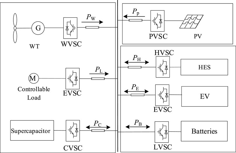
Figure 6. Structure of the test system.
The operating parameters of WTs, supercapacitors, batteries, SDL, EVs, and HES in the test system are shown in Table 1, the EV time-of-use tariffs are shown in Table 2, and the economic operating parameters of the system are shown in Table 3 (Wang et al., 2021; Wang et al., 2023). The test system solves the energy regulation model by invoking the CPLEX solver.
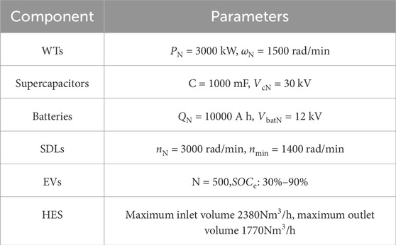
Table 1. Simulation system parameters.

Table 2. Time-of-day tariffs.
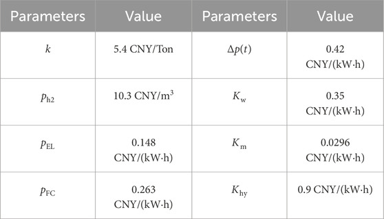
Table 3. Benefit/cost factor for economic operation of the system (Wang et al., 2023).
4.2 Analysis of energy regulation
The comparison of the test results with and without the economic optimization dispatch under the no-attachment control and VES control are shown in Figures 7–11.
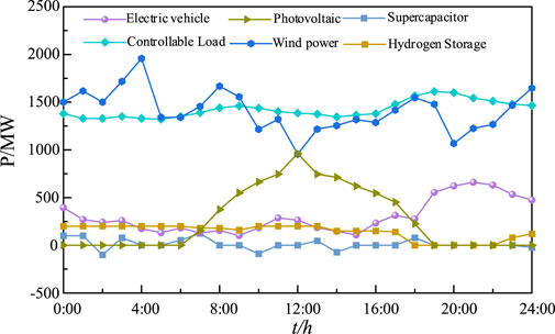
Figure 7. Power dynamic responses of the test system without additional control.
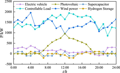
Figure 8. Power dynamic responses of the test system under VES control.
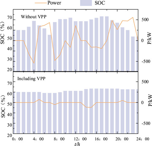
Figure 9. State of charge and power responses of the battery under two scenarios.
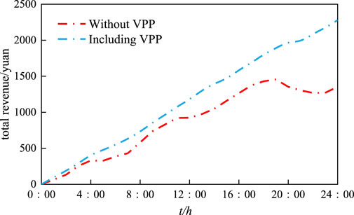
Figure 10. System gain results under two scenarios.
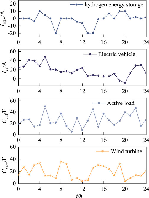
Figure 11. VCU and VCA command values.
After the introduction of VES, the energy regulation system of the microgrid scheduling and control center will generate VCA value and VCU value commands to cooperate the resources to respond to the system (Figure 11). During the economic operation scheduling process, based on the VSOC of the VES device (Figure 12), the microgrid can intuitively perceive the energy reserve state of the system.
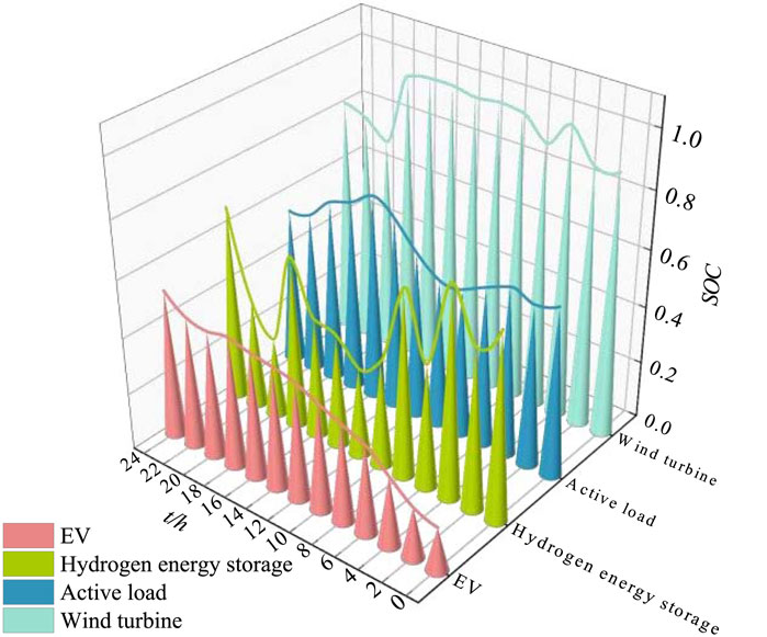
Figure 12. VSOCv of VES.
Looking at Figures 7 and 9, it can be seen that in the traditional mode without additional control—between 0:00 and 4:00—the output power of the WT increases, and the EV charging load demand is less, failing to respond to the wind power disturbance; this achieves wind power dissipation by charging the supercapacitor. In addition, at 2:00–4:00, when the supercapacitor charging reaches the limit—after the state of charge rises to the maximum value—it is handed over to the battery charging to smooth out the wind power disturbance, which makes the SOC of the battery rise to 67.4% at 4:00.
At 5:00, the wind power decreases significantly. To respond to the system power disturbance in time, the supercapacitor and the battery participate in power regulation to maintain the system power balance. At 8:00–18:00, on the one hand, the PV modules begin to generate electricity. On the other hand, the wind power plummets at 12:00, and under the pressure of this double disturbance, coupled with the limited range of supercapacitor regulation, the controllable loads as well as other controllable FRs fail to participate in the response. They mainly rely only on the hybrid energy storage system of the battery to respond to the system disturbance, leading to an increase in the depth of discharge of the battery and also putting the battery in a state of frequent charging and discharging; this causes the SOC of the battery to show a rising–declining–rising trend.
After 18:00, the EV is in a centralized charging state, and a load peak occurs, its maximum load reaching 620 kW. In addition, the PV is unable to output power at night, resulting in an increase in the system’s peak–valley difference. The batteries will be deeply discharged, and the lowest value of its SOC reaches 53.79%.
In this model, some controllable FRs (EVs, controllable loads, HES) fail to exploit their adjustable potential or fully mobilize their response. The hybrid energy storage system consisting only of supercapacitors and batteries supports the unbalanced net load caused by wind and PV power disturbances. In addition, combining Table 4 and Figure 10 shows that the net gain of the system in 24 h is ¥ 1,354.72. It is worth noting that during the dispatch cycle, the battery is in a frequent charging and discharging state; especially after 18:00, the battery is deeply discharged, which leads to an increase in the cost of operation and maintenance and aging, and the system revenue is significantly reduced.
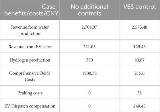
Table 4. Economy results under different cases.
After the introduction of VES, the microgrid uses the VCU and VCA values in Figure 6 to regulate the FRs and simulate the charging and discharging characteristics of energy storage devices.
As shown in Figure 11, from 0:00 to 4:00, in order to fully stimulate the responsiveness of controllable FRs and under the constraint of meeting customer charging demand, the microgrid adopts time-of-use tariffs so that EVs are charged when the price is low and discharged when the price is high, forming a phenomenon of “low storage and high generation.” In order to flexibly dispatch EVs, the microgrid generates VCU values to regulate EVs for VES. In addition, in order to tap its adjustable potential, the microgrid treats the SDL as VES and regulates the load power through the VCA value.
At 3:00, the WT sets the VCA to 37.1 F through the VES technology, which responds quickly to the power change and balances the system power. During this period, battery charging and discharging power is significantly reduced, and the microgrid effectively consumes the significantly increased wind power. At 5:00, the wind power is reduced, and the WTs are constrained by the rotational speed and wind speed. At this time, the controllable loads mainly carry out the rapid power response, and the HES and EV clusters carry out the supplemental regulation to satisfy the system power demand, fully mobilizing the enthusiasm of the VES in responding to the power change.
At 8:00–18:00, the PV begins generating power, system power redundancy, and controllable load through the VES technology to set the VCA to 22.4 F to increase the rotor speed to dissipate the redundant power. At 12:00, when the wind power plummeted—limiting the WT VES adjustable potential—the controllable load actively participated in the system regulation, reduced its own operating power, and reduced the output power to 1,642 kW. The energy regulation system generates a negative VCU value, and the HES works in the fuel cell state, increasing the output power by burning hydrogen; this reduces the number and depth of battery discharges.
After 18:00, unlike the EV as a load in the no-attachment control, the EV has already shifted the peak power consumption to other times to dissipate the wind–PV disturbances through the complementary response of the power on different periods. Therefore, at this time, the dispatch center of the microgrid sends a command to the EV with a negative value for the VCU to supply power to the system and maintain the power balance. At 24: 00, the battery SOC is controlled to be at 62.57%. At this time, compared with no additional control, the battery SOC in the VES mode is improved by 8.78%.
The test results indicated that after the introduction of VES, the maximum change of battery SOC without additional control is 12.4%, and the battery starts charging and discharging 17 times; the maximum change of battery SOC in the VES mode is 3.7%, and the battery starts charging and discharging five times. The change of battery SOC decreases in amplitude, and the fluctuation number is significantly reduced, which alleviates the depth of charging and discharging of batteries, reduces the number of times for their charging, and reduces system operation cost.
Combined with Table 4 and Figure 10, the cumulative net gain of the system in 24 h is ¥ 2,278.55. Compared to the scenario without additional control, the system’s revenue has increased by a factor of 1.68. The main reason is that after the VES participates in power regulation, although the microgrid revenue is reduced, the battery operation and maintenance costs are significantly reduced.
To test the effectiveness of the VES of EVs, this paper established three scenarios: uncontrolled charging, price-guided charging, and VES control. The comparison of the charging load curves of EVs under these three scenarios is shown in Figure 13.
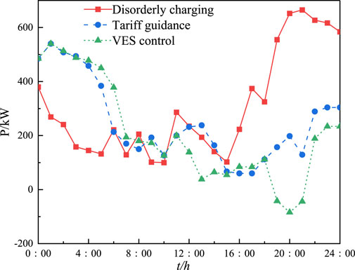
Figure 13. Load profile of EV in multiple modes.
By comparing the three scenarios, it can be seen that under the uncontrolled charging scenario, the charging behavior of EVs exhibits significant spatiotemporal clustering characteristics. The charging load of EVs surges in the evening, exacerbating the system’s peak–valley difference. The maximum charging load reaches 650 kW at 21:00, which poses a threat to the safe and stable operation of the system. Under the price-guided scenario, EVs are guided to charge in an orderly manner, concentrating their charging during the low-price period from 0:00 to 6:00, achieving a redistribution of charging load in time and space. Under the VES control scenario, EVs are centrally scheduled to supply power to the microgrid between 19:00 and 21:00, providing 194 kW of power. The results show that the participation of FRs in the coordinated operation of the microgrid can effectively regulate the resources within the grid, achieving the “peak shaving and valley filling” of the microgrid.
To validate the effectiveness of the solution proposed in this paper, its optimization results obtained are compared with those obtained from the particle swarm optimization (PSO) algorithm under the described VES control scenario. After solving with PSO, the best result among ten runs is selected and set as the VCA and VCU values to participate in the system’s energy management. The specific economic indicators obtained from solving with CPLEX and PSO are compared in Table 5.
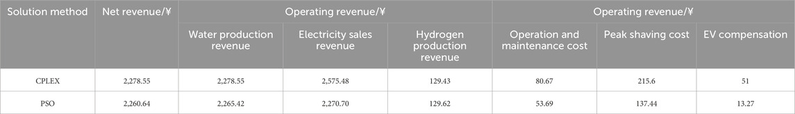
Table 5. Comparison of results from different solution methods.
The differences in the economic indicators obtained from the two solution methods are relatively small. The CPLEX solution increased the microgrid revenue by 0.81% compared to the PSO solution. This situation may be caused by the parameters set for the PSO algorithm, which may still converge to a local optimum even after multiple iterations. In contrast, the CPLEX solution method can effectively avoid the issue of falling into a local optimum and has demonstrated reproducibility through repeated validation. The comparison confirms the rationality of the solution results in this paper and indicates that using CPLEX can significantly improve the efficiency of solving the optimization model.
4.3 Analysis of frequency support effect
After 12:00, the wind power decreases abruptly after 10 s, causing the system frequency to fall and exceed the safety threshold by 0.5 Hz. The FRs in the microgrid need to respond quickly to the frequency change to guarantee the dynamic stability of the system. The system dynamic response before and after the VES is shown in Figure 14.
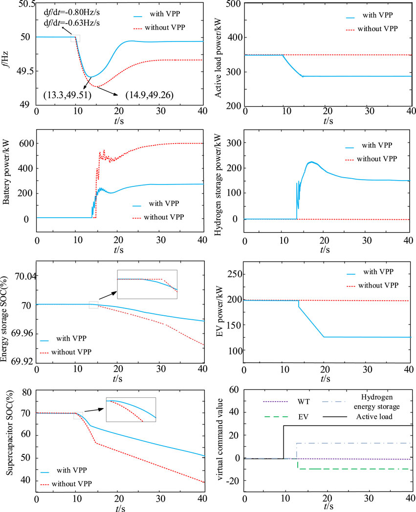
Figure 14. Dynamic responses of the system after sudden wind power reduction.
Figure 14 shows that at 10 s, the wind speed decreases suddenly, and when VES is not introduced, the supercapacitor and battery can participate in the system frequency support, but the regulation ability is insufficient, and the inertia response time is 4.9 s. At the early stage of the disturbance, the system frequency drops at a rate of 0.80 Hz/s, and the maximum frequency deviation Δfh is 0.74 Hz. The supercapacitor SOC falls to 18% in this mode. In the frequency recovery phase, the hybrid energy storage undertakes a frequency regulation task, and the frequency returns to a steady state at 31.2 s. The frequency at steady state is 49.69 Hz.
After the introduction of VES, in the inertial response stage, the system frequency change rate is 0.63 Hz/s, and the maximum frequency deviation Δfh is 0.49 Hz. The supercapacitor SOC decreases by 7.2%, which satisfies the frequency safety regulation. In this process, the controllable load shares the pressure of the supercapacitor participating in the frequency adjustment with a VCA value of 29.8 F. The supercapacitor’s SOC is also reduced by 7%. As shown in Figure 14, the load power is rapidly reduced by 129 kW, the rapid frequency response mode of the FRs is simple, and the control potential is fully released. It should be noted that if the wind power is insufficient to cause the frequency drop, the WT operates at the upper limit of the wind speed under the maximum power tracking control and cannot further increase the wind power, so the WT does not activate the VES control at low wind speeds.
After 13.3 s, the HES and EV clusters in the system frequency recovery phase participate in one frequency regulation with VCU values of 13.7 A and −7.9 A, respectively, to share the discharge pressure of the batteries. The frequency returns to the steady-state value after 25.5 s, and the frequency in the steady state is 49.92 Hz. Compared with the no-attachment control, the frequency deviation is reduced by 0.23 Hz, the amount of the change in the SOC of the batteries is significantly lower, and the frequency stability of the system is improved.
5 Conclusion
To enhance the coordinated operation performance of renewable energy, energy storage, and controllable loads, a novel cooperative control of VES is proposed to fully release the regulation potential of FRs in the microgrid across multiple time scales. Through a combination of theoretical analysis and testing verification, the following conclusions are drawn.
1) WTs, controllable loads, HES, and EVs participate in system energy regulation in the form of VES, which unifies the control parameters for the scheduling operation of various FRs into VCU and VSOC. This not only facilitates the evaluation of system energy reserves but also makes it easier to integrate with real energy storage devices for joint participation in system energy regulation.
2) With the introduction of VES, the FRs in the microgrid, under the proposed dual-layer optimization scheduling mode, can coordinate power distribution through VCU, and the system’s energy reserves can be intuitively reflected in real-time through the VSOC. The test results indicate that under the proposed optimized energy regulation mode, the system operation model is significantly simplified and the daily net revenue is increased 1.48 times, effectively enhancing the economic operation capability of the microgrid.
3) Due to the identical control parameters, EDVES and PDVES can easily cooperate with batteries and supercapacitors. During the frequency support process, they can quickly generate VCU commands, enabling the orderly response of various FRs and real energy storage devices to system frequency changes. The test results demonstrate that with the cooperative support of VES, the maximum system frequency deviation is reduced by 31%, and the frequency recovery time is shortened to 5.7 s. The desired rapid frequency response and the economic operation of the test system are both achieved.
Data availability statement
The original contributions presented in the study are included in the article/supplementary material; further inquiries can be directed to the corresponding author.
Author contributions
ZY: Data curation, Formal analysis, Investigation, Methodology, Software, and Writing – review and editing. YW: Conceptualization, Funding acquisition, Project administration, Resources, and Writing – review and editing. JW: Resources, Software, Supervision, and Writing – original draft. YC: Validation, Visualization, and Writing – review and editing.
Funding
The author(s) declare that financial support was received for the research and/or publication of this article. The work described in this paper was fully supported by a grant from the Science and Technology Project of the State Grid Jibei Integrated Energy Service Co., Ltd. (SGJBZN00AJJS2400078).
Conflict of interest
Author ZY was employed by the State Grid Jibei Integrated Energy Service Co., Ltd.
The remaining authors declare that the research was conducted in the absence of any commercial or financial relationships that could be construed as a potential conflict of interest.
The authors declare that this study received funding from State Grid Jibei Integrated Energy Service co., ltd. The funder had the following involvement in the study, including methodology, software, formal analysis, investigation and data curation.
Generative AI statement
The authors declare that no generative AI was used in the creation of this manuscript.
Publisher’s note
All claims expressed in this article are solely those of the authors and do not necessarily represent those of their affiliated organizations, or those of the publisher, the editors and the reviewers. Any product that may be evaluated in this article, or claim that may be made by its manufacturer, is not guaranteed or endorsed by the publisher.
References
Alyami, S. (2024). Management of diverse smart homes: coordination among controllable loads, EVs, and PVs. Energy Rep. 125, 5221–5233. doi:10.1016/j.egyr.2024.10.030
Cao, J., Xu, C., Zi, S., Yu, M., and Diao, R. (2025). Scenario-driven distributionally robust optimization model for a rural virtual power plant considering flexible energy-carbon-green certificate trading. Appl. Energy 379, 124904. doi:10.1016/j.apenergy.2024.124904
Chen, Q., Lyu, R., Guo, H., and Su, X. (2024). Real-time operation strategy of virtual power plants with optimal power disaggregation among heterogeneous resources. Appl. Energy 361, 122876. doi:10.1016/j.apenergy.2024.122876
Du, L., Jin, X., and He, W. (2019). A tie-line power smoothing control method for an office building microgrid by scheduling thermal mass of the building and plug-in electric vehicles. Electr. Power Constr. 40 (8), 26–33. doi:10.3969/j.issn.1000-7229.2019.08.004
Fu, S., Wang, C., Zhang, L., Chen, X., and Shu, Y. (2022). Optimized control of active loads in DC microgrids with virtual energy storage. Energy Rep. 8, 13962–13969. doi:10.1016/j.egyr.2022.10.336
Gabriele, F., Paolo, M., Marco, B., and Dimosthenis, T. (2023). The flexibility of virtual energy storage based on the thermal inertia of buildings in renewable energy communities: a techno-economic analysis and comparison with the electric battery solution. J. Energy Storage 73 (PC), 1–12. doi:10.1016/j.jes.2023.103008
Honarmand, M., Zakariazadeh, A., and Jadid, S. (2014). Optimal scheduling of electric vehicles in an intelligent parking lot considering vehicle-to-grid concept and battery condition. Energy 65, 572–579. doi:10.1016/j.energy.2013.11.045
Huang, H., Ning, Y., Jiang, Y., Tang, Z., Qian, Y., and Zhang, X. (2024). Corrigendum: dynamic pricing optimization for commercial subcontracting power supplier engaging demand response considering building virtual energy storage. Front. Energy Res. 12, 1498767. doi:10.3389/fenrg.2024.1498767
Li, Q., Dong, F., Zhou, G., Mu, C., Wang, Z., Liu, J., et al. (2025). Co-optimization of virtual power plants and distribution grids: emphasizing flexible resource aggregation and battery capacity degradation. Appl. Energy 377 (PB), 124519. doi:10.1016/j.apenergy.2024.124519
Lin, M., Liu, J., Tang, Z., Zhou, Y., Jiang, B., Zeng, P., et al. (2025). Coordinated DSO-VPP operation framework with energy and reserve integrated from shared energy storage: a mixed game method. Appl. Energy 379, 125006. doi:10.1016/J.APENERGY.2024.125006
Liu, B., Zhou, B., Yang, D., Li, G., Cao, J., Bu, S., et al. (2021). Optimal planning of hybrid renewable energy system considering virtual energy storage of desalination plant based on mixed-integer NSGA-III. Desalination 521, 115382. doi:10.1016/j.desal.2021.115382
Lv, G., Ji, Y., Zhang, Y., Wang, W., Chen, J., et al. (2023). Optimization of building microgrid energy system based on virtual energy storage. Front. Energy Res. 11, 1053498. doi:10.3389/fenrg.2022.1053498
Lv, R., Wu, E., Lan, L., Fu, C., Guo, M., Chen, F., et al. (2024). Research on virtual energy storage scheduling strategy for air conditioning based on adaptive thermal comfort model. Energies 17 (11), 2715. doi:10.3390/en17112670
Mateus, K., Wan, Y., Daniel, G., Clodomiro, U., and Tomislav, D. (2025). Review on virtual power plants/virtual aggregators: concepts, applications, prospects and operation strategies. Renew. Sustain. Energy Rev. 211, 115242. doi:10.1016/J.RSER.2024.115242
Morais, H., Pinto, T., Vale, Z., and Praça, I. (2012). Multilevel negotiation in smart grids for VPP management of distributed resources. IEEE Intell. Syst. 27 (6), 8–16. doi:10.1109/MIS.2012.105
Pahasa, J., Potejana, P., and Ngamroo, I. (2022). MPC-based virtual energy storage system using PV and air conditioner to emulate virtual inertia and frequency regulation of the low-inertia microgrid. IEEE Access 10, 133708–133719. doi:10.1109/ACCESS.2022.3231751
Shui, J., Peng, D., Zeng, H., Song, Y., Yu, Z., Yuan, X., et al. (2024). Optimal scheduling of multiple entities in virtual power plant based on the master-slave game. Appl. Energy 376 (PB), 124286. doi:10.1016/j.apenergy.2024.124286
Sun, H., Dou, Y., Hu, S., Gao, Z., Wang, Z., and Yuan, P. (2023). Day-ahead bidding strategy of a virtual power plant with multi-level electric energy interaction in China. Energies 16 (19), 6760–6815. doi:10.3390/en16196760
Tanaka, K., Yoza, A., Ogimi, K., Yona, A., Senjyu, T., Funabashi, T., et al. (2011). Optimal operation of DC smart house system by controllable loads based on smart grid topology. Renew. Energy 39 (1), 132–139. doi:10.1016/j.renene.2011.07.026
Tang, X., Hu, Y., and Geng, Q. (2021). Optimal energy management of a residential local energy network based on model predictive control. Automation Electr. Power Syst. 45 (4), 81–90. doi:10.1109/AEPS.2020.3023503
Tangqing, T., Nian, L., and Jianhua, Z. (2014). Optimal operation method for microgrid with wind/PV/diesel generator/battery and desalination. J. Appl. Math. 2014, 1–12. doi:10.1155/2014/857541
Thomas, M., Branislav, H., and Agelidis, V. G. (2018). Control strategies for microgrids with distributed energy storage systems: an overview. IEEE Trans. Smart Grid 9 (4), 3652–3666. doi:10.1109/tsg.2016.2637958
Wang, Y., Hu, C., Wu, B., Zhang, j., Zi, Z., and Kang, L. (2020). Matching characteristic research of building renewable energy system based on virtual energy storage of air conditioning load. Energies 13 (5), 1269–1314. doi:10.3390/en13051269
Wang, D., Lai, C., Li, X., Vaccaro, A., Gao, X., Lai, L. L., et al. (2021). Smart coordination of virtual energy storage systems for distribution network management. Int. J. Electr. Power Energy Syst. 129 (4), 106816. doi:10.1016/j.ijepes.2021.106816
Wang, C., Fu, S., Zhang, L., Jiang, Y., and Shu, Y. (2023). Optimal control of source-load-storage energy in DC microgrid based on the virtual energy storage system. Energy Rep. 9, 621–630. doi:10.1016/j.egyr.2022.12.002
Wang, Y., Dong, H., Ma, K., Wang, H., and Zhang, J. (2024). Multi-frequency stability optimization of integrated energy systems considering virtual energy storage characteristics of heating networks. Appl. Therm. Eng. 257 (PA), 124254. doi:10.1016/j.applthermaleng.2024.124254
Westermann, D., and Schlegel, S. (2013). Energy storage capability of battery electric vehicles. IEEE PES General Meet., 1–5. doi:10.1109/PESMG.2013.6672507
Yang, L., Guo, H., and Huang, K. (2019). Optimal dispatch for a combined cooling, heating and power micro-grid considering building virtual energy storage. J. Electr. Eng. Technol. 14 (2), 581–594. doi:10.1007/s42835-018-00055-z
Yang, W., Wen, Y., Pandi, H., and Zhang, W. (2022). A multi-state control strategy for battery energy storage based on the state-of-charge and frequency disturbance conditions. Int. J. Electr. Power Energy Syst. 135, 107600. doi:10.1016/j.ijepes.2021.107600
Yang, J., Yu, T., Zhao, H., Huang, Y., Weng, W., and Li, Y. (2025). Trading incentive mechanism and response model for high-frequency interaction between virtual power plants and main grid under spot markets. Int. J. High Speed Electron. Syst. doi:10.1142/S012915642540275X
Zhang, T., Chen, X., Yu, Z., Zhu, X., and Shi, D. (2018). A Monte Carlo simulation approach to evaluate service capacities of EV charging and battery swapping stations. IEEE Trans. Industrial Inf. 14, 3914–3923. doi:10.1109/tii.2018.2796498
Zhou, B., Liu, B., Yang, D., Cao, J., and Littler, T. (2020). Multi-objective optimal operation of coastal hydro-electrical energy system with seawater reverse osmosis desalination based on constrained NSGA-III. Energy Convers. Manag. 207, 112533. doi:10.1016/j.enconman.2020.112533
Keywords: virtual battery, virtual capacitor, energy regulation, frequency support, dynamic stability
Citation: Yang Z, Wang Y, Wei J and Cao Y (2025) Cooperative control of virtual energy storage devices for energy regulation and rapid frequency support. Front. Energy Res. 13:1574188. doi: 10.3389/fenrg.2025.1574188
Received: 10 February 2025; Accepted: 24 March 2025;
Published: 22 April 2025.
Edited by:
Yingjun Wu, Hohai University, ChinaReviewed by:
Yanbo Wang, Aalborg University, DenmarkQiang Fu, Sichuan University, China
Liwei Zhang, Northeast Electric Power University, China
Copyright © 2025 Yang, Wang, Wei and Cao. This is an open-access article distributed under the terms of the Creative Commons Attribution License (CC BY). The use, distribution or reproduction in other forums is permitted, provided the original author(s) and the copyright owner(s) are credited and that the original publication in this journal is cited, in accordance with accepted academic practice. No use, distribution or reproduction is permitted which does not comply with these terms.
*Correspondence: Yabo Cao, Y2FveWFib18yMDAwQDE2My5jb20=