 Zhao Shengqiang
 Wu Xinghua*
 Qu Shen
- Blanket Technology Research Division of the Institute of Fusion Science, Southwestern Institute of Physics, China National Nuclear Corporation, Chengdu, China
As deuterium-tritium (D-T) fusion experiments progress, radiation shielding is a fundamental requirement for ensuring personnel safety of fusion devices. This study utilizes neutron-photon coupling code to analyze the penetration of high-energy neutrons through various shielding materials in spatially constrained fusion experimental devices. The effectiveness of neutron shielding was evaluated through transmission factor measurements. Following the principle of “moderation before absorption,” different material combinations were optimized to enhance neutron attenuation. Simulation results indicate that a three-layer shielding configuration (i.e., comprising tungsten carbide (WC, 30 cm), boron-doped polyethylene (PEB, 10 cm), and boron carbide (B4C, 10 cm)) provides shielding effectiveness nearly an order of magnitude higher than a 50 cm boron-doped PEB monolith, while exceeding the performance of a 50 cm WC monolith by 50%. Furthermore, verification through a plant neutron transport model confirmed consistency with simplified shielding calculation model simulation trends, validating the selection of optimized shielding materials. These results offer valuable insights for designing effective radiation shielding in future fusion reactor applications.
1 Introduction
Fusion energy is widely regarded as a promising solution to address the future global energy crisis, attracting significant research interest. Extensive studies on fusion technology have been conducted both domestically and internationally, leading to the development of several large-scale fusion experimental devices, primarily tokamaks. Notable examples include JT-60U (Ninomiya, 1992), joint European torus (JET) (Keilhacker et al., 1999), tokamak fusion test reactor (TFTR) (Strachan et al., 1997), HL-3 (Zhong, 2024), and experimental advanced superconducting tokamak (EAST) (Shen et al., 2016). Among fusion reactions, deuterium-tritium (D-T) reaction has the highest cross-section, making it the most feasible for achieving sustained fusion under current technological constraints. This reaction produces 14.1 MeV high-energy neutrons, which exhibit strong penetration capabilities (Kiptily et al., 2003). In a tokamak facility, neutron radiation outside the containment area can generate high levels of ionizing radiation. Additionally, interactions between high-energy neutrons and surrounding materials can induce secondary gamma radiation, posing potential safety hazards to personnel and the environment. For example, neutron leakage in the JET experiment caused radiation doses to exceed safety limits (Bell et al., 1999; Murari et al., 2008). Therefore, effective radiation protection measures are essential for fusion experimental devices and must be established before conducting D-T fusion experiments.
During the 1990s, extensive research on radiation protection for fusion experimental devices was conducted internationally, exploring various materials and shielding designs. JET facility employs reinforced concrete walls with boron (B) block linings, complemented by boron carbide (B4C) mortar on the top and floor to enhance shielding effectiveness (Caldwell-Nichols et al., 1992). Similarly, TFTR utilizes ordinary concrete walls in conjunction with boronized limestone floors and additional concrete shielding plates on the inner walls to improve radiation attenuation (Kugel et al., 1995). The JT-60 facility, in contrast, adopts a combination of concrete and polyethylene (PE) to optimize neutron shielding performance (Sukegawa et al., 2010). Currently, certain fusion experimental devices in China have not yet conducted D-T reaction validation experiments, with radiation protection studies remaining relatively understudied in this domain. Given the stringent shielding requirements associated with D-T fusion (i.e., particularly in spatially constrained environments) identifying and optimizing efficient material combinations is of critical importance for future fusion reactor development.
2 Methods
Fusion experimental devices where spatial constraints are a limiting factor, excessively thick shielding materials may fail to meet both radiation protection standards and architectural requirements. Therefore, the primary challenge lies in selecting and optimizing shielding material combinations to minimize structural thickness while maintaining high shielding efficiency. This study aims to identify optimal shielding material configurations through a systematic process of analysis and optimization. Firstly, a comprehensive survey of commonly used shielding materials is conducted, considering key neutron interaction characteristics to establish a simplified shielding calculation model. Secondly, neutron-photon coupling code are performed on different material configurations, including single-layer, double-layer, and triple-layer structures. In the single-layer analysis, materials with high efficiency in absorbing both fast and thermal neutrons are selected. For double-layer configurations, these materials are paired strategically to enhance neutron attenuation. Finally, in the triple-layer configurations, boron-doped polyethylene (PEB) (i.e., known for its superior moderation of intermediate-energy neutrons) is strategically positioned between two layers to optimize neutron absorption and scattering. To verify the shielding effectiveness of the optimized material combinations, they are further tested in a plant neutron transport model, allowing for a comprehensive evaluation of shielding performance under realistic conditions. Through this process, material configurations that achieve stronger shielding effects with reduced thickness are identified, offering valuable insights for the development of radiation protection strategies in future D-T fusion experimental devices.
2.1 Model development
A simplified shielding calculation model is developed in Figure 1. This model consists of three primary components: the radiation source term, shielding material, and spherical shell detector. To ensure accuracy in neutron transport analysis, the radiation source is positioned at a fixed distance from the shielding material, with its incident direction perpendicular to the shielding surface. This setup minimizes neutron scattering in undesired directions, which could otherwise affect statistical accuracy. The initial shielding material is modeled as a rectangular block with dimensions 10 cm × 400 cm × 1,250 cm, and a reflector layer is incorporated in the cross-section to enhance neutron moderation. The shielding material thickness is varied from 10 cm to 50 cm during the simulation. To maintain consistency in neutron flux measurements, the distance between the detector and the shielding material is kept constant throughout the simulations, ensuring that variations in neutron counts are only attributed to shielding effectiveness rather than changes in spatial positioning.

Figure 1. Schematic of simplified shielding calculation model.
2.2 Calculation
The neutron-photon coupled simulation was implemented using MCNP 4C (Hammersley, 2013). A point neutron source with isotropic angular distribution and an energy of 14.1 MeV was employed. The energy cutoff thresholds for neutrons and photons were set to 1 × 10⁻⁸ keV and 1 keV, respectively. Variance reduction techniques, including geometry splitting and Russian roulette, were applied to enhance computational efficiency. Executed on a high-performance computing platform equipped with 4,102 CPU cores to ensure accurate and efficient computational analysis. In this study, the neutron transmission factor is employed as a key metric to evaluate the shielding performance of various materials. The neutron transmission factor
N: denotes the detector neutron flux measured with shielding materials in place. N0: represents the baseline neutron flux obtained without any shielding configuration.
A lower neutron transmission factor indicates a higher shielding effectiveness of the material, demonstrating superior neutron attenuation. In this study, the statistical errors associated with the simulation calculations are maintained at less than 5%, ensuring the reliability and accuracy of the results.
3 Simulation and analysis of simplified shielding calculation model
3.1 Selection of shielding materials
The high-energy neutrons generated by D-T fusion exhibit strong penetration capabilities, necessitating effective shielding strategies. To attenuate these neutrons, a multi-stage process occurs: fast neutrons initially undergo inelastic scattering interactions with high atomic number materials, reducing their energy to below 1 MeV. At this stage, neutrons are more likely to experience elastic scattering interactions with low atomic mass materials, further moderating their energy until they become thermal neutrons. Finally, thermal neutrons are effectively absorbed by elements with high thermal neutron absorption cross-sections, preventing further interactions. Table 1 outlines the scattering cross-sections and thermal neutron absorption cross-sections for various elements (International Atomic Energy Agency). The data indicate that elements with high inelastic scattering cross-sections include 186W, 184W, 157Gd, while elements with high elastic scattering cross-sections include 1H, 56Fe, 157Gd. Additionally, elements such as 10B, 184W, 157Gd exhibit high thermal neutron absorption cross-sections. Based on these neutron interaction properties, materials selected for shielding should incorporate the aforementioned elements wherever possible. Considering additional factors such as weight reduction and cost efficiency, ten shielding materials were chosen for further investigation in this simulation, these materials possess high irradiation stability and are easily accessible. Table 2 summarizes the elemental composition and physical density of the selected shielding materials. For materials with simpler compositions, only physical density is specified (Williams, 2011).
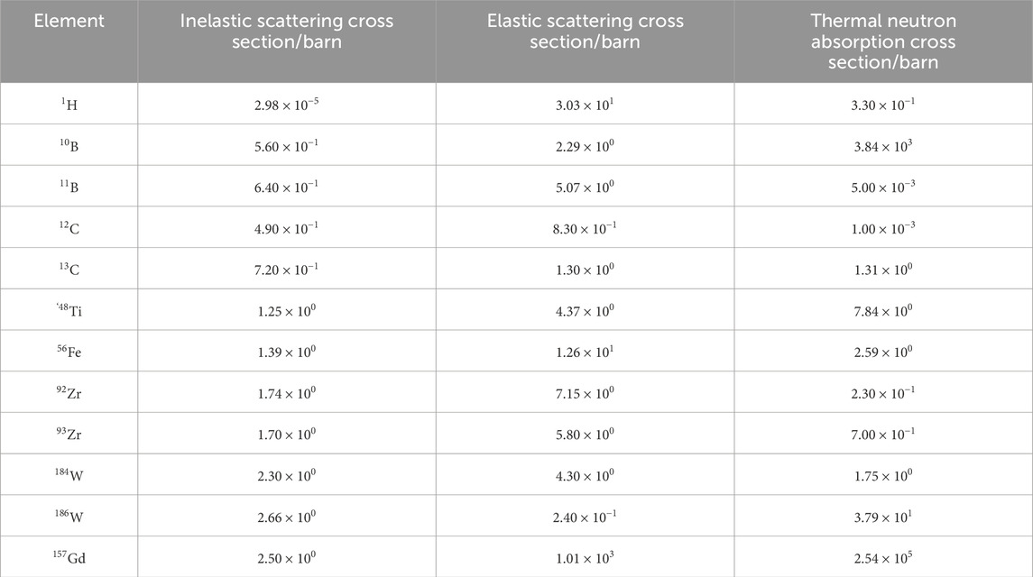
Table 1. Scattering and thermal neutron absorption cross sections of selected elements.
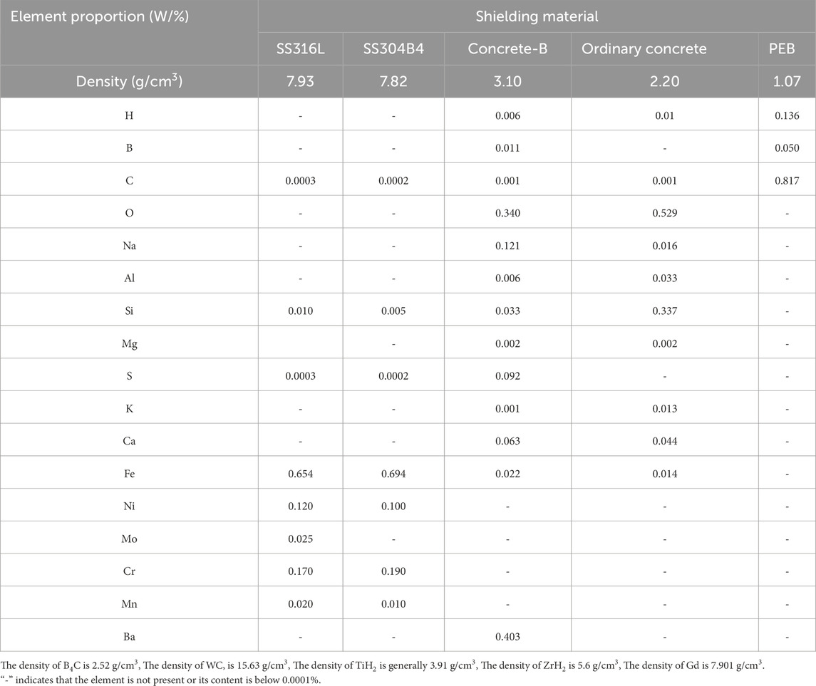
Table 2. Elemental composition and physical density of selected shielding materials.
3.2 Performance of single-layer materials
Using simplified shielding calculation model in Figure 1, the selected shielding materials were individually incorporated into the simulation framework for evaluation. Figure 2 illustrates the neutron energy spectrum generated through the plasma region in D-T fusion reactions, characterized by a primary energy of 14.1 MeV. The results indicate that, after traversing the fusion experimental device, the neutron population predominantly consists of fast neutrons (E > 0.1 MeV), with only a small fraction of thermal neutrons (E < 0.1 MeV) present. Limited thermal neutrons result from activation-induced secondary neutrons and structural materials within the fusion device, which contribute to secondary neutron production.
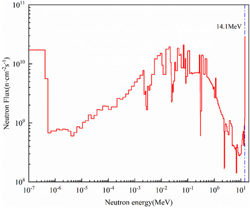
Figure 2. Energy spectrum of incident neutrons from plasma region.
The curve of the total neutron transmission factor as a function of shielding material thickness (Figure 3) demonstrates that tungsten carbide (WC) exhibits the lowest transmission factor among the selected materials. As the thickness increases from 0 cm to 50 cm, the transmission factor of WC decreases by six orders of magnitude, indicating superior neutron shielding performance. In contrast, ordinary concrete shows a significantly lower shielding efficiency, with its transmission factor decreasing by only three orders of magnitude over the same thickness range, making it the least effective shielding material in this study. Notably, while gadolinium (Gd) possesses a high thermal neutron absorption cross-section, its overall shielding performance does not meet expectations based on simulation results. The incident neutron spectrum analysis reveals that the majority of neutrons passing through Gd layer are fast neutrons. Due to insufficient moderation upon entering the material, these high-energy neutrons penetrate through without significant attenuation. Consequently, Gd primarily absorbs thermal neutrons generated after neutron interactions with the fusion device’s structural materials, leading to poor absorption of fast neutrons and a relatively weak overall neutron shielding effect.
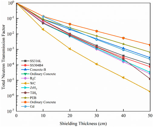
Figure 3. Variation of total neutron transmission factor with shielding material thickness.
Figure 4 depicts the transmission factor curves for fast and thermal neutrons as a function of shielding material thickness. The results indicate that WC exhibits the lowest fast neutron transmission factor among the materials analyzed, with its effectiveness improving as the shielding thickness increases. With a density of 15.63 g/cm3, WC contains a high concentration of tungsten (W) and carbon (C) per unit mass. W component plays a crucial role in neutron moderation, effectively reducing the energy of fast neutrons. Additionally, the presence of 186W isotope (28.43% in W) contributes to its thermal neutron absorption, boasting a large absorption cross-section of 37.86 b. This combination makes WC an effective shielding material for both fast and thermal neutrons. In comparison, while titanium hydride (TiH2) exhibits improved neutron shielding performance with increasing thickness, it is less effective than WC due to its lower density (approximately four times lower than WC). However, combining TiH2 with other shielding materials may enhance its overall performance. In Figure 4a, B4C demonstrates the fastest reduction in thermal neutron transmission factor as shielding thickness increases. This behavior is attributed to the high 10B content in B4C, which comprises 17.98% of B composition and features a large thermal neutron absorption cross-section of 3,837 b. Therefore, B4C is highly effective in absorbing thermal neutrons. Simulation results further reveal that PEB exhibits a relatively lower total neutron transmission factor compared to other shielding materials. Therefore, achieving enhanced shielding effectiveness would require an increase in PEB thickness. Despite this limitation, PEB’s low density and lightweight properties make it advantageous for shielding applications. Furthermore, PEB demonstrates strong elastic scattering and neutron moderation capabilities for neutrons below 1 MeV, making it particularly suitable for combination with materials that excel in fast neutron deceleration.
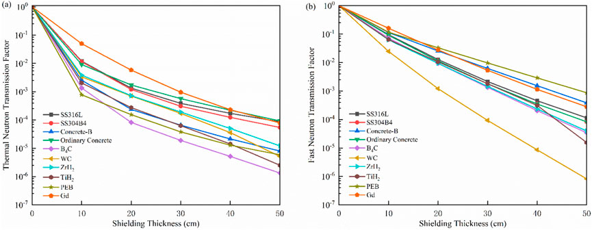
Figure 4. Comparison of thermal (a) and fast (b) neutron transmission factors across different shielding materials.
3.3 Performance of double-layer materials
The analysis of single-layer shielding materials indicates that WC and various hydride materials effectively moderate fast neutrons, whereas B4C and PEB excel in absorbing and moderating thermal neutrons. Based on these results, double-layer shielding combination scheme is proposed to enhance neutron attenuation. In this scheme, the total shielding thickness is maintained at 50 cm. The first layer consists of materials with high inelastic scattering cross-sections, which effectively slow down fast neutrons. The second layer is composed of materials with high thermal neutron absorption cross-sections, ensuring efficient absorption of thermalized neutrons (Li et al., 2023). To facilitate statistical analysis, the thickness of the first layer is incrementally increased by 2 cm, while the second layer’s thickness is reduced by 2 cm to maintain a constant 50 cm total thickness. The specific matching scheme is detailed in Table 3.
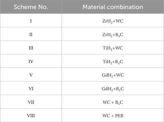
Table 3. Design schemes for double-layer shielding materials.
Figure 5 illustrates the variation in neutron transmission factor for different double-layer shielding configurations. When hydride materials are used as the first layer and WC as the second layer, the transmission factor initially increases before subsequently decreasing as the thickness of the hydride layer increases. This initial increase occurs because, when the hydride layer is thin, the primary shielding effect is dominated by WC, which, in a single-layer configuration, provides stronger shielding than the hydride materials. However, as the thickness of the hydride layer increases, WC layer becomes thinner, thereby weakening the overall shielding effectiveness and causing an increase in neutron transmission factor. Beyond a certain threshold, when the hydride layer becomes sufficiently thick, it assumes the primary role in neutron moderation, leading to an overall reduction in neutron transmission factor. For hydride-based combinations with B4C, gadolinium hydride (GdH2)-B4C and zirconium hydride (ZrH2)-B4C configurations exhibit an overall increasing trend in neutron transmission factor, indicating that this combination does not enhance shielding performance effectively. However, TiH2-B4C combination demonstrates a continuous decrease in neutron transmission factor as TiH2 layer thickness increases. When 48 cm of TiH2 is combined with 2 cm of B4C, the neutron transmission factor is reduced by 40% and 15% compared to using B4C and TiH2 individually. Furthermore, this combination results in an 84% reduction in weight compared to using WC alone, making it a promising material for applications where weight reduction is a critical factor, such as top building structures in fusion facilities. Additionally, WC-B4C combination demonstrates significant neutron shielding performance. When WC layer thickness ranges from 32 cm to 40 cm, and B4C layer thickness ranges from 10 cm to 18 cm, the neutron transmission factor reaches 10–5, achieving a 63% and 84% reduction compared to using WC and B4C individually.
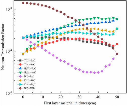
Figure 5. Neutron transmission factor for different double-layer shielding material combinations.
3.4 Performance of three-layer materials
To further enhance neutron shielding performance, the optimal WC-B4C combination identified in the previous analysis is augmented with PEB. Following dual-layer simulation, the WC-B4C composite demonstrates optimal shielding performance with a WC material thickness ranging between 30 and 40 cm. The addition of PEB is intended to leverage its high elastic scattering cross-section, thereby improving the moderation of intermediate-energy neutrons. As neutrons pass through WC layer, their energy is reduced to approximately 1 MeV, at which point PEB layer effectively slows them down further into thermal neutrons. These thermalized neutrons are then absorbed by B4C layer, enhancing the overall radiation shielding efficiency. The three-layer shielding material combination scheme is outlined in Table 4.

Table 4. Optimized three-layer shielding material combinations and configurations.
In Figure 6, the neutron transmission factors for all three-layer shielding configurations are reduced by approximately 50% compared to a 50 cm WC monolithic shield. Among the evaluated schemes, Scheme III exhibits the best shielding performance, not only enhancing neutron attenuation but also reducing overall material weight by 29% compared to WC alone. This significant weight reduction presents a promising shielding solution for fusion experimental devices. However, further verification using a plant neutron transport model is required to confirm its effectiveness in practical applications.
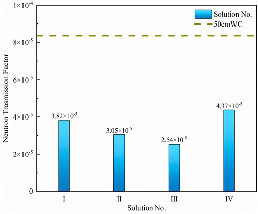
Figure 6. Comparison of neutron transmission factors for three-layer shielding material combinations and WC.
4 Simulation and analysis of plant neutron model
A plant neutron transport model was developed using MCNP4C version, initially excluding shielding materials to establish a baseline neutron transport behavior. The model incorporates key structural components, including the tokamak main device, tokamak hall, ground concrete, and an inclusion containment shield. The initial model dimensions are based on current international fusion shielding research and the geometric parameters of existing domestic fusion devices. An isotropic D-T neutron source is positioned at the center of the device, accounting for neutron interactions with ground concrete and air. Given the high-energy neutron flux and the complex plant geometry of the fusion device, the simulation calculations implement variance reduction techniques, such as cell importance weighting and weight window technology, by controlling the weight range of particles within specific regions, it ensures sufficient particle contribution in critical areas, thereby reducing variance and enhancing computational efficiency (Che et al., 2024; Zhang et al., 2024). Figure 7 depicts the cross-sectional view of the fusion experimental device building hall and inclusion Containment shield using Monte Carlo code.
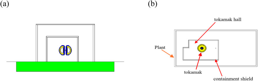
Figure 7. Cross-sectional view of fusion experimental device hall and containment shield: (a) py = 0; (b) pz = 0.
To validate the applicability and shielding performance of the radiation shielding material configurations selected through a simplified physical model in the plant-level neutronics simulations, an integrated assessment was performed. In response to supplemental constraints, including top-section structural loading limits and neutron flux perturbations induced by atmospheric scattering and vertical refractive effects, the shielding material in the upper region of the shielding assembly has been uniformly designed as PEB. The shielding configuration will be positioned on the side of the internal containment shield assembly proximal to the fusion device. For a 10 MW D-T fusion device, the neutron yield is ∼3.55 × 10¹⁸ n/s, calculated based on the D-T reaction cross-section and the device’s thermal power.
Figure 8 illustrates several shielding configurations that demonstrate effective neutron attenuation at varying levels of performance. To evaluate their effectiveness, these configurations were implemented into plant neutron transport model (Figure 7). To assess neutron flux distribution, the detection point is set at 1.5 meters above ground level, consistent with ICRP’s recommended standing height for radiation monitoring, with 1-m intervals along the left wall of the main hall. The variation in neutron transmission factors for different shielding combinations as a function of distance is presented in Figure 9. The simulation results indicate that Scheme IV exhibits the lowest neutron transmission factor, achieving a reduction of approximately one order of magnitude compared to the 50 cm PEB monolithic shield. Although Scheme IV sacrifices certain structural weight efficiency, the significant improvement in radiation protection justifies its implementation. Furthermore, Scheme IV reduces the neutron transmission factor by approximately 45% relative to Schemes II, III, and V, while maintaining a lighter overall weight than the other tested configurations.
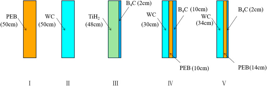
Figure 8. Comparison of different infill patterns in plant neutron shielding model.
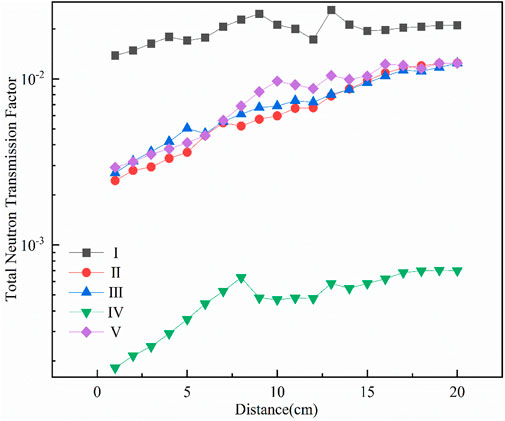
Figure 9. Variation of neutron transmission factor as a function of distance.
The neutron flux of Scheme IV was obtained using F card counting in combination with the neutron source strength. The neutron energy spectrum corresponding to Scheme IV is depicted in Figure 10. As neutrons pass through the first layer of WC material, Figure 10a illustrates a decreasing trend in neutron flux across different energy regions. To better visualize neutron energy distribution changes, the neutron flux was normalized (Figure 10b). The results indicate a significant reduction in fast neutron flux after passing through WC layer, with the overall energy spectrum shifting toward the low-energy region. This confirms that WC, due to its isotopes with high inelastic scattering cross-sections, effectively attenuates fast neutrons. In the left portion of Figure 10b, a noticeable increase in neutron flux is observed in the epithermal neutron region (E < 0.01 MeV). This increase occurs because certain fast neutrons are moderated to epithermal energy levels rather than being completely absorbed. However, after passing through the second layer of PEB, the neutron flux in the epithermal energy range decreases from 107 to 105, representing a two-order magnitude reduction, while the fast neutron flux remains relatively unchanged. The most significant decrease is observed in the intermediate-energy neutron region, confirming that isotopes with high elastic scattering cross-sections effectively moderate intermediate-energy neutrons. Finally, upon passing through the third layer of B4C, the thermal neutron flux is almost entirely absorbed, leading to an overall decrease in neutron flux. This confirms that 10B, with its high thermal neutron absorption cross-section, plays a critical role in neutron absorption. Overall, these results validate Scheme IV as an optimal shielding configuration, making it a promising option for radiation shielding in future D-T fusion experiments.
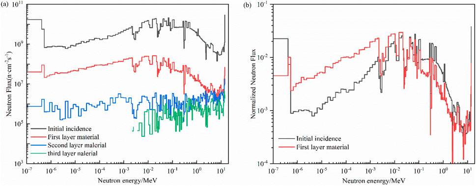
Figure 10. Neutron energy spectrum of plant neutron transport model for Scheme Ⅳ: (a) illustrates the neutron flux distribution during penetration through successive shielding slabs, (b) compares the incident neutron flux with the flux transmitted through the first shielding slab, normalized to the incident flux.
5 Conclusion
This study evaluates neutron shielding performance, material weight, and cost considerations to identify optimal shielding material combinations for D-T fusion experimental devices. Using neutron-photon coupling code, the attenuation of high-energy neutrons was analyzed across different shielding configurations. The research results provide insights into material selection and structural optimization for effective neutron shielding. The key conclusions derived from the simulation results are outlined as follows:
(1) In a simplified shielding calculation model, WC and hydride-based materials exhibit superior fast neutron absorption, while TiH2 and PEB demonstrate effective thermal neutron absorption.
(2) For a 50 cm double-layer shielding configuration, where WC thickness ranges from 30 cm to 40 cm and B4C thickness ranges from 10 cm to 20 cm, the neutron transmission factor is reduced by 63% and 84%, respectively, compared to using single-layer WC or B4C alone.
(3) When 48 cm of TiH2 is combined with 2 cm of B4C, the neutron transmission factor is reduced by 15% and 40%, respectively, compared to using 50 cm of TiH2 or B4C alone.
(4) In a simplified shielding calculation model, WC-PEB-B4C combination achieves a 50% reduction in the neutron transmission factor compared to using WC alone, demonstrating enhanced neutron attenuation efficiency
(5) Using a plant neutron transport model, Scheme IV achieves a one-order-of-magnitude reduction in neutron transmission factor compared to PEB alone, while also exhibiting 50% enhancement in shielding effectiveness compared to a single layer of WC and achieving 29% reduction in weight. This makes Scheme IV a strong candidate for radiation shielding applications in future fusion experimental devices.
(6) Practical Considerations:The shielding materials selected in the current solution are readily available but present certain limitations: for instance, the interfacial bonding of multilayered shielding materials requires careful consideration, and the current design has yet to address the swelling effects induced by boron-containing polyethylene. These challenges will be systematically resolved during subsequent engineering phases. Although the combined shielding scheme demonstrates superior shielding performance, its large-scale application may lead to prohibitively high costs. Potential niche applications could include the development of portable shielding equipment or localized protection for critical components in compact fusion devices.
Data availability statement
The original contributions presented in the study are included in the article/supplementary material, further inquiries can be directed to the corresponding author.
Author contributions
ZS: Formal Analysis, Software, Validation, Writing – original draft, Conceptualization, Investigation, Methodology. WX: Project administration, Validation, Writing – review and editing. CQ: Funding acquisition, Resources, Software, Visualization, Writing – review and editing. QS: Data curation, Funding acquisition, Resources, Software, Supervision, Writing – review and editing, Project administration. ZL: Conceptualization, Resources, Writing – review and editing. ZF: Data curation, Formal Analysis, Investigation, Validation, Writing – review and editing. YM: Data curation, Validation, Visualization, Writing – review and editing.
Funding
The author(s) declare that financial support was received for the research and/or publication of this article. This research was supported by China National Nuclear Corporation Basic Research Project on the development of new high-temperature-resistant and efficient shielding materials (Project No. CNNC-JCYJ-202238), National Natural Science Foundation of China (Grant No. 12205077), Southwestern Institute of Physics (Grant No. 2024YFE03070001), and Science and Technology Foundation of Sichuan Province (Grant No. 2024NSFSC0419). The authors express their sincere gratitude for this financial and technical support.
Conflict of interest
The authors declare that the research was conducted in the absence of any commercial or financial relationships that could be construed as a potential conflict of interest.
Generative AI statement
The author(s) declare that no Generative AI was used in the creation of this manuscript.
Publisher’s note
All claims expressed in this article are solely those of the authors and do not necessarily represent those of their affiliated organizations, or those of the publisher, the editors and the reviewers. Any product that may be evaluated in this article, or claim that may be made by its manufacturer, is not guaranteed or endorsed by the publisher.
References
Bell, A. C., Ballantyne, P., Gordon, C., and Wright, M. (1999). The safety case for JET D-T operation. Fusion Eng. Des. 47 (2-3), 115–130. doi:10.1016/S0920-3796(99)00080-0
Caldwell-Nichols, C. J., Russ, R. M., Bell, A. C., Davies, N., Haigh, A., Jones, H., et al. (1992). Radiation monitoring, environmental and health physics aspects during the first JET tritium experiment. Fusion Eng. and Des. 19 (2), 149–159. doi:10.1016/0920-3796(92)90069-G
Che, R., Liu, S., Tian, Z., and Chen, Y. (2024). Verification of shielding calculation capability of cosRMC with SINBAD fusion benchmarks. Fusion Eng. Des. 203, 114465. doi:10.1016/j.fusengdes.2024.114465
Giroletti, E., Bonomi, G., Donzella, A., Viesti, G., and Zenoni, A. (2012). Radiological risks from irradiation of cargo contents with EURITRACK neutron inspection systems. Radiat. Phys. and Chem. 81 (7), 758–765. doi:10.1016/j.radphyschem.2012.03.014
International Atomic Energy Agency. EXFOR: experimental nuclear reaction data. IAEA. Available online at: https://www-nds.iaea.org/exfor/endf.htm (Accessed December 17, 2024).
Keilhacker, M., Gibson, A., Gormezano, C., Lomas, P., Thomas, P., Watkins, M., et al. (1999). High fusion performance from deuterium-tritium plasmas in JET. Nucl. Fusion 39 (2), 209–234. doi:10.1088/0029-5515/39/2/306
Kiptily, V. G., Popovichev, S., Sharapov, S. E., Bertalot, L., Cecil, F. E., Conroy, S., et al. (2003). Gamma-diagnostics of alpha-particles in He4 and D–T plasmas. Rev. Sci. Instrum. 74 (3), 1753–1756. doi:10.1063/1.1534922
Kugel, H. W., Ascione, G., Elwood, S., Gilbert, J., Ku, L. P., Levine, J., et al. (1995). Measurements of tokamak fusion test reactor D-T radiation shielding efficiency. Fusion Eng. Des. 28 (7), 534–544. doi:10.1016/0920-3796(95)90080-2
Li, R., Liu, S., Zhang, X., Xiaoming, C., Junyun, Y., Qianming, H., et al. (2023). Nuclides selection method for nuclear reactor shielding based on non-dominated sorting. Ann. Nucl. Energy 182, 109633. doi:10.1016/j.anucene.2022.109633
Murari, A., Edlington, T., Angelone, M., Bertalot, L., Bolshakova, I., Bonheure, G., et al. (2008). Measuring the radiation field and radiation hard detectors at JET: recent developments. Nucl. Instrum. methods Phys. Res. 593, 492–504. doi:10.1016/j.nima.2008.05.058
Ninomiya, H. (1992). JT-60U latest results and future prospects. Phys. Fluids B Plasma Phys. 4 (7), 2070–2080. doi:10.1063/1.860480
Shen, Y. C., Lyu, B., Wang, F. D., Shi, Y. J., Wu, B., Li, Y. Y., et al. (2016). Observation of molybdenum emission from impurity-induced long-lived m = 1 mode on the experimental advanced superconducting tokamak. Chin. Phys. Lett. 33, 065205. doi:10.1088/0256-307X/33/6/065205
Strachan, J. D., Batha, S., Beer, M., Bell, M. G., Bell, R. E., Belov, A., et al. (1997). TFTR DT experiments. Plasma Phys. and Control. Fusion 39 (39), B103–B114. doi:10.1088/0741-3335/39/12B/008
Sukegawa, A. M., Kawasaki, H., and Okuno, K. (2010). Conceptual radiation shielding design of superconducting tokamak fusion device by PHITS. Aesj. Or. Jp. cache.yimg.Jp. 2, 375–381. doi:10.15669/pnst.2.375
Williams, R. G. (2011). Compendium of material composition data for radiation transport modeling. Richland, WA, United States: Pacific Northwest National Laboratory (PNNL). doi:10.2172/1023125
Zhang, X., Liu, S., Li, S., and Chen, Y. (2024). Development of multilevel mesh adaptivity for global variance reduction in Monte Carlo code cosRMC. Fusion Eng. Des. 202, 114372. doi:10.1016/j.fusengdes.2024.114372
Keywords: neutron shielding, radiation protection, multi-layer shielding, Monte Carlo simulation, neutron analysis
Citation: Shengqiang Z, Xinghua W, Qixiang C, Shen Q, Long Z, Fengchao Z and Miao Y (2025) Deuterium tritium fusion experiment device radiation shielding analysis and optimization. Front. Energy Res. 13:1581903. doi: 10.3389/fenrg.2025.1581903
Received: 23 February 2025; Accepted: 23 April 2025;
Published: 06 May 2025.
Edited by:
Shichang Liu, North China Electric Power University, ChinaReviewed by:
Tengfei Zhang, Shanghai Jiao Tong University, ChinaOussama Mehelli, Ecole Militaire Polytechnique (EMP), Algeria
Qingming He, Xi’an Jiaotong University, China
Chen Zhao, Nuclear Power Institute of China (NPIC), China
Yuefeng Qiu, Karlsruhe Institute of Technology (KIT), Germany
Copyright © 2025 Shengqiang, Xinghua, Qixiang, Shen, Long, Fengchao and Miao. This is an open-access article distributed under the terms of the Creative Commons Attribution License (CC BY). The use, distribution or reproduction in other forums is permitted, provided the original author(s) and the copyright owner(s) are credited and that the original publication in this journal is cited, in accordance with accepted academic practice. No use, distribution or reproduction is permitted which does not comply with these terms.
*Correspondence: Wu Xinghua, d3V4aEBzd2lwLmFjLmNu