 Yangqing Dan1
 Licheng Sun
- 1State Grid Zhejiang Electric Power Co., Ltd., Hangzhou, Zhejiang, China
- 2School of Automation, Wuhan University of Technology, Wuhan, Hubei, China
To improve power distribution control in systems with multiple Distributed Power Flow Controller (DPFC) sub-units, this study addresses the limitations of conventional strategies such as equal distribution and capacity ratio methods, which often result in low device utilization and high power losses, especially under low line regulation conditions. A novel DPFC topology is analyzed to understand device output characteristics and sub-unit loss mechanisms. Focusing on output voltage and capacity utilization, the research proposes a coordinated output control strategy that comprehensively considers total system losses, utilization rates of sub-units, and operational constraints. Simulation results demonstrate that the proposed method significantly enhances power flow control efficiency and reduces losses compared to traditional approaches, offering improved performance in scenarios with minimal line regulation requirements.
1 Introduction
With China’s deepening environmental protection concepts and the advancement of “dual carbon” goals, new energy power generation—represented by wind and solar energy—is rapidly expanding. However, the integration of new energy power sources presents novel challenges to the power system. On one hand, the volatility and intermittency of new energy generation intensify the uncertainty in power systems. On the other hand, large-scale grid connection of new energy sources has led to significant changes in power flow characteristics, with traditional transmission lines facing issues such as overload and bidirectional power flow. These uncontrolled power flows not only result in insufficient power supply in some regions and high transmission losses but may also reduce system stability and reliability.
The novel Distributed Power Flow Controller (DPFC), as an innovative flexible AC transmission device, demonstrates unique advantages in addressing these challenges. Compared to traditional DPFC, the most distinctive feature of the new DPFC is the addition of a shunt-side energy collection device. This innovative design enables the shunt converter to provide reactive power compensation while establishing harmonic circuits through the transformer neutral point to provide active power support for the series side, thus achieving coordinated series-shunt control. This improvement maintains the original DPFC advantages of low cost, high reliability, small footprint, and strong scalability while significantly enhancing system regulation capability and energy utilization efficiency.
Current research in novel DPFC primarily focuses on several aspects:
1. System modeling and analysis, where researchers strive to establish precise mathematical models considering series-shunt coupling effects
2. Control strategy optimization, including series-shunt coordinated control and multi-objective optimization control
3. Engineering application research, mainly exploring novel DPFC applications in scenarios such as large-scale new energy grid connection and microgrids
However, recent studies have shown that there is still significant room for optimization of DPFC control strategies. Literature (Song et al., 2021; New Distribution System, 2021; Wang et al., 2021; DE et al., 2018) conducted a comprehensive review of loss minimization in distributed power systems, pointing out that the balance between equipment utilization and loss is a key challenge in current research. Literature (Abas et al., 2020) proposed a coordinated control strategy that considered equipment aging and efficiency, and improved the overall efficiency of the system by dynamically adjusting the working state of each subunit. In terms of multi-objective optimization, literature. (Liu et al., 2007). took the uncertainty of renewable energy into account and proposed a DPFC optimization model with greater adaptability. Literature (Das et al., 2010) used deep reinforcement learning technology to realize the coordinated control of multiple DPFC in AC/DC hybrid power system, providing a new idea for equipment coordination under complex working conditions. The application of neural network technology in DPFC control has also made a breakthrough. Literature (Lu et al., 2023) developed an adaptive control scheme based on machine learning, which can automatically adjust control parameters according to different working conditions, and significantly improve the system stability under the infiltration condition of high proportion of renewable energy. Literature (Shahnia et al., 2014) proposed a hybrid optimization method combining gray Wolf optimization and particle swarm optimization, which achieved good results in the optimal placement and operation control of DPFC. Literature (Alwash et al., 2023; Zolfaghari et al., 2022; Qian et al., 2024; Chen et al., 2023; Zhang et al., 2023) comprehensively evaluated the application value of DPFC in renewable energy grid-connection from the perspective of power grid toughness, and proposed a comprehensive evaluation framework. However, existing research still has some limitations: most control methods fail to fully utilize the regulation capability of the shunt side; the series-shunt coordination mechanism needs improvement; and system overall efficiency and economic performance still have room for enhancement. Recent improved methods, such as optimization allocation based on state classification and cluster control strategies, have made progress in some aspects but still need enhancement in regulation speed, operational losses, and equipment utilization. When using the averaging method with inconsistent sub-unit capacities, larger-capacity sub-units have low utilization rates, and the entire system’s control range is constrained by the smallest capacity sub-unit, resulting in poor economic efficiency. With the proportional method, power output is distributed according to sub-unit capacity ratios, leading to low overall device utilization and high losses when regulation requirements are small.
Literature (Zhang et al., 2023) proposes centralized management and optimization allocation schemes for DPFC, completing optimization allocation tests of DPFC main control units based on real-time digital simulation systems. Literature (Luo et al., 2023) proposes a real-time optimization allocation method for sub-module regulation based on “state classification and regulation performance priority determination.” While these optimization schemes in (Zhang et al., 2023; LUO et al., 2023) require multiple rounds of debugging, resulting in slow regulation speed, their priority determination targets only device adjustable capacity. This leads to high device operation losses when regulation targets are small, with large-capacity sub-modules operating long-term while small-capacity sub-modules have low utilization, resulting in poor economic benefits and safety.
Literature (Wang et al., 2025) proposes a cluster control strategy enabling distributed flexible AC transmission devices to maintain stable compensation efficiency throughout the operating range but does not consider device capacity differences and operational losses. Literature (Yang et al., 2024) proposes DPFC sub-unit control switching strategies through centralized control, enriching DPFC application scenarios and enhancing application flexibility, but essentially remains an averaging method (Jie et al., 2024; Chen et al., 2024; Yutao et al., 2024; Yifei et al., 2024).
Based on the novel DPFC topology, this paper analyzes device losses in detail, including shunt-side third harmonic output devices. Considering device capacity differences and operational loss variations (Yuduo et al., 2022; Zhang et al., 2018; Zhou et al., 2020), we propose a DPFC coordinated output control strategy (hereinafter referred to as “coordinated output method”) that can reduce overall device losses while improving sub-unit utilization from both output voltage and capacity utilization perspectives. PSCAD/EMTDC simulation analysis is used to verify the effectiveness of the proposed coordinated output control strategy.
The main innovations and contributions of this paper are as follows:
1. Based on the new DPFC topology, the equipment loss mechanism is analyzed in detail, especially the whole system loss including the third harmonic output device on the grid-connected side is systematically modeled
2. A novel DPFC coordinated output control strategy is proposed, which is optimized on the two core dimensions of output voltage and capacity utilization, achieving a significant reduction in equipment loss and a substantial increase in unit utilization.
3. The control strategy has a flexible unit selection mechanism, which can dynamically determine the number and type of input units according to the system adjustment demand, effectively solving the problem of low equipment utilization rate under the low adjustment demand of traditional average method and proportional method.
4. While ensuring accurate voltage regulation, the proposed method significantly improves the utilization efficiency of large-capacity units and reduces the overall system loss, providing a new technical scheme for the practical engineering application of distributed power flow controllers.
Compared with the existing methods, the coordinated output control strategy proposed in this paper has higher equipment utilization efficiency and lower system loss. It is especially suitable for low regulation demand scenarios and has important significance for improving energy utilization efficiency and equipment economy of distribution network.
2 Novel DPFC topology and operational loss analysis
2.1 Traditional DPFC topology structure
A complete DPFC system consists of multiple DPFC sub-units, with the traditional DPFC sub-unit structure shown in Figure 1.
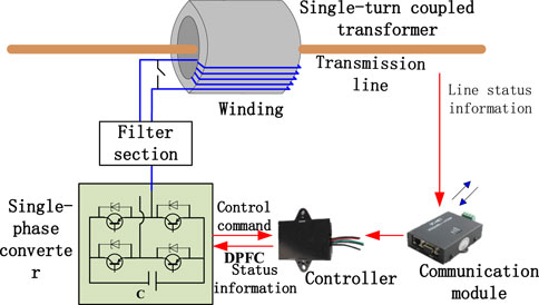
Figure 1. Traditional DPFC sub-unit.
The traditional DPFC device consists only of multiple series units, with its equivalent circuit model shown in Figure 2. In this model, SA1, SA2, SB1, and SB2 are the switching tubes on each bridge arm, Lse is the single-phase converter filter inductor, Rse is the line equivalent resistance, Cdc is the DC capacitor, Udc is the single-phase converter capacitor voltage, Rloss is the single-phase converter loss, Use is the single-phase converter output voltage, U1 is the ground voltage at the series side left connection point, U2 is the ground voltage at the right connection point, iR is the converter output current, i is the DPFC AC side output current after LC filtering, and Cse is the filter capacitor.
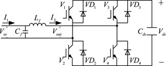
Figure 2. Novel DPFC shunt-side topology.
2.2 Novel DPFC topology structure
Compared to traditional DPFC, the novel DPFC system adds a shunt-side energy collection device. The shunt-side converter can provide reactive power compensation to the system and generate harmonics through the transformer neutral point to form a circuit providing active power support for the series side. In Figure 2, Us is the line sending-end voltage, Ur is the line receiving-end voltage, Use is the voltage output to the line through the series module (with adjustable amplitude and phase angle), I is the line current, and P is the line transmission power.
The topology structure diagram of the novel DPFC device is shown in Figure 3 below.

Figure 3. Novel DPFC device topology structure diagram.
2.3 Novel DPFC line operation loss analysis
If the series side stabilizes DC-side capacitor voltage through self-energy collection, line power flow control can only be achieved by injecting voltage at 90° to the line current, limiting the voltage control range to a line, as shown in the control phasor diagram in Figure 4. In Figure 4, Usec is the output voltage under capacitive compensation, Usel is the output voltage under inductive compensation on the shunt side, Urc is the receiving-end voltage under capacitive compensation, and Url is the receiving-end voltage under inductive compensation.
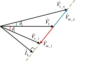
Figure 4. Series-side control phasor relationships based on self-energy collection.
Figure 4 shows the control phasor relationship of DPFC series side in its own energy collection mode. In this figure, Usec represents the output voltage vector under capacitive compensation, Vse_i represents the output voltage vector under inductive compensation, IL represents the line current vector, Vr_c represents the receiving voltage vector under capacitive compensation, Vr_i represents the receiving voltage vector under inductive compensation, and V1 represents the transmitting voltage. The phasor diagram clearly shows the mechanism of DPFC’s influence on the line voltage under different compensation modes: When the series side stabilizes the DC capacitor voltage through its own energy collection, the line power flow control can only be achieved by injecting a voltage of 90° with the line current into the line, which limits the control range of the voltage on the line. The angles
The DPFC series system contains multiple DPFC series units. Different series system power distribution methods result in different power allocations to each DPFC series unit by the distribution controller. Therefore, when each unit adjusts the transmission line according to its allocated power output, the device losses will also differ. According to DPFC operating principles, device losses during line compensation and regulation work can be divided into single-phase converter losses and line coupling transformer losses. Single-phase converter losses mainly include IGBT (Insulated Gate Bipolar Transistor) switching losses and freewheeling diode losses, while line coupling transformer losses include core losses and copper losses. This is shown in Equation 1 below.
Where: Eon(t) and Eoff(t) represent the turn-on and turn-off energy losses of the IGBT switch respectively; t is time; fs is the carrier frequency; T is the PWM (Pulse Width Modulation) modulation wave period; Rgon and Rgoff are the gate turn-on and turn-off resistances of IGBT under actual operating conditions; E(Rgon) and E(Rgoff) are the losses generated by the IGBT gate resistance during IGBT turn-on and turn-off processes under rated current conditions; kon and koff are the IGBT turn-on and turn-off loss coefficients; As shown in Equations 2, 3. the IGBT turn-on loss coefficient is represented by Equation 4.
According to Equation 5, the turn-off loss coefficient can be expressed as:
Without considering dead time, Si1(ti) and Si2(ti) are:
Where: E(Rgon_t) and E(Rgoff_t) are the factory test values of gate resistance turn-on and turn-off energy consumption under rated current; Eon_t and Eoff_t are the factory test values of IGBT turn-on and turn-off energy consumption per switching under rated current; Ut is the as shown in Equation 6, the IGBT loss during normal operation is:
Where: UCE(t) is the voltage time function generated between the IGBT collector and the emitter, and the unit is V; IC(t) is the time function of the current flowing through the IGBT collector, the unit is A; DQ(t) is the duty cycle of The total loss of the secondary tube is calculated by Equation 7, and the conduction loss, switching loss, and switching energy are calculated by Equations 8–10.
Where: Pon_D and Poff_D are the losses of diode in conduction and cut-off states respectively; UF(t) is the time function of voltage across the diode; IF(t) is the time function of current flowing through the diode; DT is the duty cycle of the diode; kDre is the loss coefficient corresponding to diode turn-off; EreR(Rg) is the gate resistance reverse recovery energy consumption; Ere(t) is the switching function corresponding to the diode.
The formula for calculating the core loss is shown in Equation 11.
Where: Pc is the core loss, the unit is W; K is the coefficient, which is related to the material characteristics of the iron core. f is the current frequency, unit is Hz; B is the magnetic induction intensity, the unit is T; α is an empirical coefficient with a typical value of 1.5–2.5 and no dimension; Calculation of copper loss can be done by using Equation 12:
Where: IL is the DPFC series control line current, the unit is A; ρ is the resistivity of the inductor, in Ω·m; l is the length of the inductor coil, in m; Scnil is the cross-sectional area of the inductor, expressed in m2.
the total transformer losses as shown in Equation 13 with the following:
Based on the above analysis, the total loss of DPFC series units and equipment after they are put into operation (Equation 14) is:
Where: PZ is the total loss generated after DPFC series unit equipment is put into operation, and the unit is W; Ps is IGBT switching loss, unit is W; P0 is diode loss, and the unit is W; Pw is the loss of the single-phase converter during normal operation, and the unit is W; PT is the transformer loss, expressed in W.
A comparison of the topological structures between conventional DPFC and the novel DPFC device is shown in Figure 5.

Figure 5. Schematic diagram comparing different DPFC topologies.
3 Novel DPFC device loss control strategy
3.1 Analysis of conventional power distribution methods
DPFC units are connected in series to power lines in a distributed manner. Based on different power line operating conditions, DPFC can achieve three regulation modes—impedance, voltage, and power flow—by modifying external control objectives. Therefore, in different DPFC operation modes, the corresponding DPFC losses can be expressed by Equation 15:
where Usei, Xsei, Ssei (i = 1,2,.,n, where n is the number of DPFC units connected in series) represent the equivalent voltage, equivalent impedance, and equivalent apparent power injected into the line by DPFC units, respectively.
The equivalent circuit model of multiple novel DPFC controlled power sources is shown in Figure 6. In this equivalent circuit, the reference phase is based on the line current phase, where Usei and θsei represent the magnitude and phase of the injection voltage of the ith DPFC series unit into the line, X and R represent the equivalent reactance and resistance on the DPFC branch of the power system, Us and δs represent the magnitude and phase of the line sending-end voltage, and Ur and δr represent the magnitude and phase of the line receiving-end voltage.
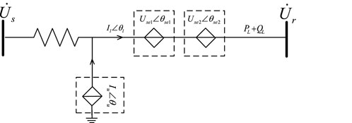
Figure 6. New DPFC Equivalent Circuit Model.
Figure 6 shows the equivalent circuit models of several new DPFC control power supplies. In this equivalent circuit, the line current phase is taken as the reference phase, where Usei and θsei respectively represent the voltage injected into the line by the DPFC series unit, X and R respectively represent the equivalent reactance and resistance on the DPFC branch of the power system, Us and δs respectively represent the voltage size and phase of the line sending terminal. Ur and δr represent the magnitude and phase of the line receiving terminal voltage, respectively. IL indicates the line current, Iu indicates the parallel side current. PL + QL indicates line power.
Instead, the active and reactive components of the line power flow can be calculated by Equations 16, 17 as:
where δsr is the phase difference between the sending-end voltage Us and receiving-end voltage Ur. It is evident that to control the active and reactive power flow of the power line, the most direct method is to control the output voltage Usei of DPFC units to the line.
Current power distribution strategies for multiple DPFC units mainly include averaging and proportional methods. The averaging method distributes power output equally among DPFC units based on the total output demand of the entire series system. The proportional method distributes power output according to the specific capacity of each DPFC unit. When the DPFC series system adopts the averaging method, defining UseΣ as the total required compensation voltage for the line, the output (i.e., the injection voltage Usei of the As shown in Equation 18, the output voltage of each DPFC unit is:
Replace: At this point, the total equipment loss of the DPFC series system is represented by Equation 19:
When the DPFC series system adopts the proportional method, defining SseΣ as the total installed capacity of the series system, Ssei as the rated capacity of series unit i, and hi as the proportion coefficient of a single series unit to the total installed capacity, When the proportional method is used for DPFC series systems, the total installed capacity can be calculated using Equation 20:
The capacity scaling factor for each cell is shown in Equation 21 as follows:
The output of each DPFC unit can be obtained from Equation 22:
At this point, the total DPFC equipment loss can be expressed by Equation 23 as:
Considering the possibility of equipment failure or change in operational status, the operational status variable Ds is introduced (Equation 24):
The output scheme changes accordingly. When this method is used, the output of each series of cells becomes the form shown in Equation 25:
At this point, the DPFC device loss is given by Equation 26:
When using the proportional method, the total installed capacity, capacity proportion coefficient, and series unit output all change. The total installed capacity can be calculated using Equation 27:
At this point, the DPFC equipment loss is represented by Equation 30:
Ssefi is represented by Equation 31:
When Usei = 0, Ssefi = 0, the DPFC series unit utilization rate is 0%. Evidently, the averaging method can effectively improve the average utilization rate of the DPFC series system, while the proportional method can address the limitation of larger capacity DPFC units being constrained by smaller capacity units. However, when the system’s total regulation requirement is small, regardless of whether the averaging or proportional method is used, all DPFC units must be operational, which reduces DPFC unit device utilization, shortens device lifespan, and affects operational reliability.
3.2 Coordinated processing control strategy considering series-parallel energy exchange
This study develops a coordinated output control strategy for DPFC series system units by considering device output voltage and capacity utilization, comprehensively accounting for total losses of the novel DPFC device, sub-unit utilization rates, and relevant constraints. DPFC series unit system-level control strategy is subject to multiple constraints, and finding the optimal solution from multiple constraints in practical analysis is a multi-objective optimization problem. Instead, a coordinated control strategy is proposed based on the concept of multi-objective constrained optimization (Equation 32):
where F(x) is the multi-objective function; fi(x) represents the sub-objective functions for each constraint condition, N is the number of sub-objective functions; x is the independent variable requiring optimization design; gj(x) represents inequality constraint conditions of the multi-objective function, JA is the number of inequality constraints; hk(x) represents equality constraint conditions of the multi-objective function, KA is the number of equality constraints. To ensure normal operation of DPFC series units in the line, the following constraint conditions must also be satisfied:
1. Total DPFC injection voltage constraint requirement (Equation 33) (i.e., the sum of output voltages from each series unit equals the system’s total required voltage):
2. The power flow constraints are shown in Equation 34 as follows:
where PL,ref is the reference value of active power for the controlled power line; PL,min and PL,max are the lower and upper limits of active power for the controlled power line, respectively.
3. The equipment capacity constraints are shown in Equation 35 as follows:
where Ur,i is the rated output voltage of DPFC series unit i; ke is the efficiency constraint coefficient, set to 0.8.
4. Transformer voltage constraint (Equation 36) with:
where Use min i is the minimum voltage required for driving the converter; Usemaxi is the maximum allowable injection voltage into the transmission line for DPFC series unit i.
5. Transformer capacity constraint as shown in Equation 37:
where STNi is the rated power of the single-turn coupling transformer between DPFC series unit i and the transmission line. To effectively regulate the controlled line power flow while reducing DPFC series unit losses, a control system optimization function is constructed. In order to efficiently regulate the controlled line power flow and reduce the DPFC device losses, a system optimization model is proposed (Equation 38):
where Ji is the control system optimization performance function; λ is a constant. The objective function given by Equation 39, the output voltage evaluation function as in Equation 40, and the capacity utilization evaluation function as in Equation 41:
where K(ui) is the loss function corresponding to DPFC sub-units; U(ui) and C(ui) are the evaluation functions for output voltage and capacity utilization of corresponding DPFC series system operating sub-units, respectively.
The final optimization function (Equation 42) is constructed using the Lagrangian method of:
The optimal solution parameters are shown in Equation 43 as follows;
The voltage control quantity Umin corresponding to Jmin is calculated, and the resulting control quantity directly serves as the input to the DPFC series system for the line.
Based on the above analysis, the implementation steps of the DPFC coordinated output control strategy are as follows:
1. Determine whether the active power and reactive power target values PLref and QLref for controlled line power flow regulation are within the specified constraint range: if within the specified range, proceed to the next step; if exceeding the specified range, the system line power flow regulation target needs to be adjusted to within constraints.
2. Determine whether the active and reactive power flow regulation requirements of the controlled line are within the adjustable range of the DPFC series system: if within the DPFC series system’s regulation range, proceed to the next step; if exceeding the DPFC series system’s adjustable range, readjust the power flow regulation requirements.
3. Combining Equations 18, 19, calculate the total compensation voltage UseΣ for the DPFC series system to regulate the active and reactive power of the controlled line. Under the constraint conditions of Equations 34–39, use neural network methods to solve Equation 42 (Jie et al., 2024) to obtain the DPFC output allocation scheme.
4. Finally, issue output allocation commands to each DPFC series unit, and each unit regulates the controlled line power flow according to the commands.
In this paper, the method based on BP neural network is used to solve the above multi-objective optimization problems. The structure of the neural network is designed as follows: the input layer contains parameters such as the system regulation requirement, the capacity of each subunit and the current state. The hidden layer was composed of three layers, and the number of neurons in each layer was 20, 15 and 10, respectively. The output layer outputs the optimal output voltage distribution scheme of each DPFC subunit. Levenberg-Marquardt algorithm was adopted for network training. The learning rate was set to 0.01, the momentum factor was set to 0.9, the maximum number of iterations was set to 5,000 and the target error was set to 10-6.
The main reasons for choosing neural networks over other optimization algorithms (such as genetic algorithms, particle swarm algorithms, etc.) are:
1. Real-time requirement: the calculation speed of neural network is fast after completion of training, which is suitable for DPFC real-time control application scenarios
2. Nonlinear mapping ability: This problem involves complex nonlinear mapping relationships, and neural networks have natural advantages in dealing with such problems
3. Generalization performance: The trained network can deal with the optimization solution under various working conditions and has good generalization ability
4. Engineering practicability: Neural network is easy to implement in embedded control system and easy for engineering application
The network training data is obtained through a large number of power system simulations, covering various operating conditions, including different load levels, various fault conditions and optimal distribution schemes under various control objectives. The network convergence ensures that the average error on 1,000 test samples is less than 3% through cross-validation of verification sets, which meets the requirements of engineering applications. The calculation procedure for DPFC losses is illustrated in Figure 7.
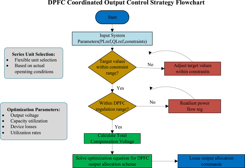
Figure 7. Flow chart of DPFC loss calculation.
The time complexity of DPFC coordinated output control strategy is mainly derived from the forward computation process of neural network. Assuming that the DPFC system contains n sub-units, the neural network contains L hidden layers, and the maximum number of neurons in each layer is M, the time complexity of the algorithm is O (LM2+nM). In practical applications, since L and M are relatively fixed, the time complexity can be simplified to O(n), which shows a linear growth, which ensures the scalability of the algorithm in large-scale DPFC system.
In this paper, the convergence of the algorithm is verified both theoretically and experimentally. In theory, since the multi-objective optimization problem is convex under given constraints, the neural network solution satisfies the convergence condition of gradient descent method after transformation by Lagrange multiplier method. The experimental results show that in 50 test cases of different sizes (the number of subunits varies from 5 to 50), the algorithm can converge to the solution with an error range of less than 1% in an average of 15 iterations, and the convergence time is approximately linear with the number of subunits.
In order to verify the performance of the algorithm on different scale problems, we tested DPFC systems with 10, 20, 30, 40 and 50 subunits respectively, and obtained an average calculation time of 15 ms, 28 ms, 42 ms, 56 ms and 69 ms respectively, which meets the requirements of real-time control of power systems (usually requiring response time less than 100 ms). The stability of the algorithm is verified by Monte Carlo simulation. Under the condition of parameter random disturbance ±10%, the control effect changes by less than 3%, which shows that the algorithm has good robustness.
4 Simulation analysis
The simulation system structure used in this study is shown in Figure 8. The specific parameters are: sending-end voltage Us effective value is 65.1 kV; receiving-end voltage Ur effective value is 63.5 kV; phase difference between sending and receiving end voltages is 8°; transformer rated capacity is 0.5 kVA; leakage inductance is 0.0002 p. u.; silicon steel sheet thermal conductivity kg = 18 W/(m·K); copper thermal conductivity kt = 398 W/(m·K); under natural cooling conditions, room temperature is set to 30°C; heat transfer coefficient α = 10–14 W/(m2·K); the equivalent impedances of internal power sources at both system ends are selected as Z1 = j0.0628 Ω and Z4 = j0.0314 Ω; the system line conductor type is LGJ-400, line L1 conductor length is 20 km, line L2 conductor length is 25 km, calculated impedance Z2 is (1.59 + j7.722) Ω, impedance Z3 is (1.92 + j9.286) Ω. Ten DPFC series units are installed on line L2, divided into groups A and B: the first five series units (numbered 1–5) have identical capacities, with each unit’s rated capacity being 0.1 MVA and rated output voltage being 0.15 kV, classified as DPFC series unit group A; the latter five series units (numbered 6–10) have identical capacities, with each unit’s rated capacity being 0.2 MVA and rated output voltage being 0.3 kV, classified as DPFC series unit group B.
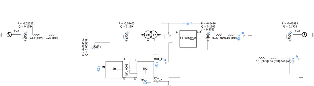
Figure 8. Simulation system structure.
The simulation steps are as follows:
1. At 0.3s, engage the primary system of all DPFC series units and the DC-side capacitor voltage control module of single-phase converters. The DC-side capacitor voltage target value for DPFC series unit group A is 1.8 kV, and for group B is 3 kV.
2. At 1.5s, perform voltage compensation for the line according to the three different output distribution methods described earlier, with the total target value of required compensation voltage for the controlled line being 0.9 kV.
The DPFC series system output distribution method proposed in this paper aims to reduce device losses and improve device utilization. Therefore, the simulation results for DC capacitor voltage Udc, line active power PL, output voltage UseΣ, and line current IL are consistent across all three output distribution methods. The coordinated output method alone is used to demonstrate the complete process from DPFC initial engagement to line power flow regulation, as shown in Figure 9.
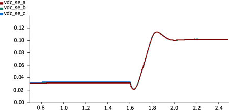
Figure 9. Dc capacitor voltage of each unit in the new DPFC
As shown in Figure 10, at around 0.8s, the DC capacitor voltages of all DPFC series units steadily reach their target values; all series units in group A reach their target value (1.8 kV) and engage after 1.5 s. From Figure 11, it can be observed that around 1.6 s, the DC capacitor voltages of all DPFC series units steadily reach their target values. All series units reach their target values and engage in line regulation after 2.0 s, at which point the capacitor voltage shows slight fluctuations, consistently stabilizing within ±0.5% of the target value.
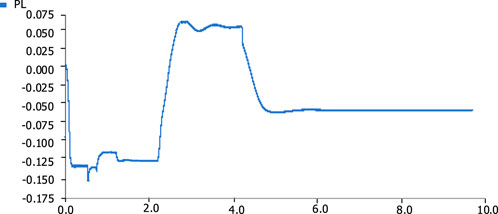
Figure 10. Controlled power flow in the line.
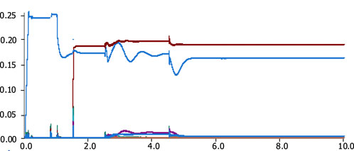
Figure 11. Third harmonic on the series side.
As shown in Figure 12's simulation results, the averaging method does not consider potential capacity differences between series units. This issue becomes prominent when system adjustment requirements are low and direct capacity differences between devices are large, resulting in low device utilization. Compared to the averaging method, while the proportional method frees the entire DPFC series system’s regulation capability from the constraints of minimum capacity devices, it cannot resolve the issue of units being unable to receive higher power output when the overall adjustment amount is small. Furthermore, both methods engage all series units in operation, which may prevent system regulation targets from being achieved when certain series units in the system experience failures. Figure 13 shows the proportion of different types of losses for DPFC.
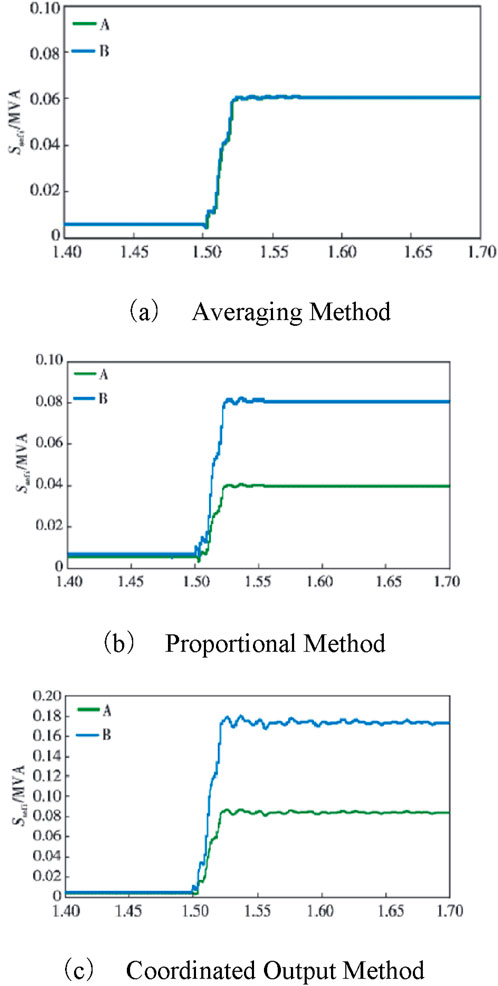
Figure 12. Capacity usage of each series unit under different output allocation methods. (A) Averaging method; (B) proportional method; (C) coordinated output method.

Figure 13. Capacity usage of each series unit under different output allocation methods.
The coordinated output method proposed in this paper can flexibly select the number and types of series units to engage based on system regulation requirements while ensuring higher device utilization rates for all operating series units. This device utilization rate includes both the ratio of actual output voltage to rated output voltage and the ratio of used capacity to rated capacity, as detailed in Table 1.
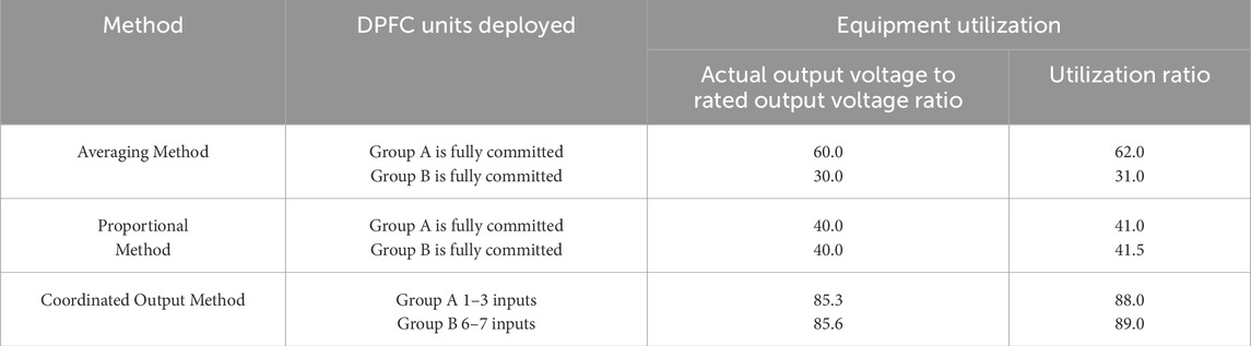
Table 1. DPFC series unit utilization.
From Table 2, it is evident that the coordinated output method shows clear advantages in both the number of engaged units and device utilization rates, maintaining output voltage and capacity utilization above 85% of rated values. With the first two methods, series units may operate in low-efficiency states for extended periods, and with excessive device engagement, the overall device losses of the series system are higher.
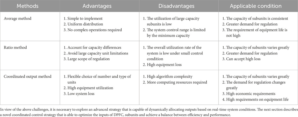
Table 2. Different methods have differences and applicable conditions.
5 Conclusion
This paper first categorized and analyzed DPFC series system device losses and calculated individual device output and total device losses based on current conventional output methods. To improve series unit device utilization while precisely regulating line voltage and reducing DPFC series system device losses, this paper proposed a DPFC series unit coordinated output control strategy. Using the PSCAD/EMTDC simulation platform, 10 DPFC series units were divided into two groups based on capacity and simulated in a typical 110 kV system. The simulation provided DPFC series system unit output conditions and device losses under different output distribution methods, leading to the following conclusions:
1. The system-level coordinated output control strategy proposed in this paper for DPFC series systems can ensure precise voltage regulation of DPFC series units on the line;
2. While ensuring series unit operational reliability, compared to traditional averaging and proportional methods, the coordinated output control strategy can flexibly engage series units based on actual operating conditions, significantly improving device utilization rates, achieving actual output voltage above 85% of rated values and device capacity utilization above 88% of rated values; 3. Compared to DPFC series system total device losses when using averaging or proportional methods, the coordinated output control strategy proposed in this paper can reduce overall DPFC series system device losses by approximately 50%.
Although the coordinated output control strategy proposed in this paper shows obvious advantages in reducing equipment loss and improving equipment utilization, the research still has the following limitations and further exploration directions:
1. Practical application challenges: In practical engineering applications, the accurate acquisition of system parameters and real-time communication may face challenges, especially in large-scale distribution networks, requiring further research on robust control strategies based on limited and incomplete information.
2. Algorithm scalability: Although theoretical analysis shows that the algorithm has good scalability, in a very large scale DPFC system (such as more than 100 subunits), the algorithm performance and communication overhead need to be further verified and optimized.
3. Integration with other control strategies: Combining the coordinated output strategy proposed in this paper with advanced technologies such as adaptive control and predictive control may further improve system performance, which is an important direction for future research.
4. Balance between economy and reliability: Although this paper mainly focuses on equipment loss and utilization, in practical applications, it is necessary to consider equipment life, maintenance costs and other factors to establish a more comprehensive economic evaluation model.
5. Uncertainty factors: In the face of increased system uncertainty brought about by new energy access, how to design a robust DPFC coordinated control strategy to cope with power fluctuations and system parameter changes, etc., still needs in-depth research.
Data availability statement
The original contributions presented in the study are included in the article/supplementary material, further inquiries can be directed to the corresponding author.
Author contributions
YD: Writing – original draft. HZ: Conceptualization, Data curation, Writing – original draft. JW: Data curation, Writing – original draft. YF: Data curation, Methodology, Writing – original draft. LY: Conceptualization, Methodology, Writing – original draft. LS: Conceptualization, Writing – original draft.
Funding
The author(s) declare that financial support was received for the research and/or publication of this article. This research was funded by the Technology Project of State Grid Zhejiang Electric Power Research Institute technology projects grant number (B311JY240008).
Acknowledgments
This article is grateful to State Grid Zhejiang Electric Power Co. Ltd. Project for funding.
Conflict of interest
Authors YD, HZ, and JW were employed by State Grid Zhejiang Electric Power Co. Ltd.
The remaining authors declare that the research was conducted in the absence of any commercial or financial relationships that could be construed as a potential conflict of interest.
The authors declare that this study received funding from o State Grid Zhejiang Electric Power Co. Ltd. The funder had the following involvement in the study: undertook the work of study design and data collection in this paper.
Generative AI statement
The author(s) declare that no Generative AI was used in the creation of this manuscript.
Publisher’s note
All claims expressed in this article are solely those of the authors and do not necessarily represent those of their affiliated organizations, or those of the publisher, the editors and the reviewers. Any product that may be evaluated in this article, or claim that may be made by its manufacturer, is not guaranteed or endorsed by the publisher.
References
Abas, N., Dilshad, S., Khalid, A., Saleem, M. S., and Khan, N. (2020). Power quality improvement using dynamic voltage restorer. IEEE Access 8, 164325–164339. doi:10.1109/access.2020.3022477
Alwash, S., Ibrahim, S., and Abed, A. (2023). Distribution system reconfiguration with soft open point for power loss reduction in distribution systems based on hybrid water cycle algorithm. Energies 16 (1), 199. doi:10.3390/en16010199
Chen, L. I., Yao, D. A. I., Peng, WANG, et al. (2023). Active and reactive power coordinated optimization of active distribution networks considering dynamic reconfiguration and SOP. IET Renew. Power Gener., 1–12. doi:10.1049/rpg2.12814
Chen, Y., Wang, P., Chen, F., et al. (2024). The application of distributed positioning technology in distribution network fault location. Electr. Equip. Econ. (02), 91–94.
Das, D., Divan, D. M., and Harley, R. G. (2010). Power flow control in networks using controllable network transformers. IEEE Trans. Power Electron. 25 (7), 1753–1760. doi:10.1109/TPEL.2010.2042076
DE, ARAUJOLR, Penido, D. R. R., Carneiro, S., and Pereira, J. L. R. (2018). Optimal unbalanced capacitor placement in distribution systems for voltage control and energy losses minimization. Electr. Power Syst. Res. 154, 110–121. doi:10.1016/j.epsr.2017.08.012
Jie, JIAN, Jinli, ZHAO, Haoran, J. I., Bai, L., Xu, J., Li, P., et al. (2024). Supply restoration of data centers in flexible distribution networks with spatial-temporal regulation. IEEE Trans. Smart Grid 15 (1), 340–354. doi:10.1109/tsg.2023.3286844
Liu, L., Zhu, P., Kang, Y., and Chen, J. (2007). Power-flow control performance analysis of a unified power-flow controller in a novel control scheme. IEEE Trans. Power Deliv. 22 (3), 1613–1619. doi:10.1109/TPWRD.2006.886799
Lu, M., Qin, M., Kacetl, J., Suresh, E., Long, T., and Goetz, S. M. (2023). A novel direct-injection universal power flow and quality control circuit. IEEE J. Emerg. Sel. Top. Power Electron. 11 (6), 6028–6041. doi:10.1109/JESTPE.2023.3321882
Luo, Z., Sun, Y., Hang, Li, Xiao, Y., Liu, B., Wang, T., et al. (2023). Power management and coordinated control strategy of flexible interconnected AC/DC hybrid microgrid with back-to-back converters. Int. J. Circuit Theory Appl. 51 (11), 5173–5196. doi:10.1002/cta.3694
Qian, R., Yuan, X., Zou, X., et al. (2024). SOP low voltage ride through control strategy based on characteristic impedance of feeder line. Guangdong Electr. Power 37 (06), 70–78. doi:10.3969/j.issn.1007-290X.2024.06.008
Shahnia, F., Ghosh, A., Ledwich, G., and Zare, F. (2014). Voltage unbalance improvement in low voltage residential feeders with rooftop PVs using custom power devices. Int. J. Electr. Power and Energy Syst. 55, 362–377. doi:10.1016/j.ijepes.2013.09.018
Song, M., Tao, J., Zhang, H., et al. (2021). “Autonomous-synergic control of reactive voltage of distribution network considering renewable energy access,” in Proceedings of the CSU-epsa, 34, 38–47.9
Tang, A., Lulu, M. A., Peng, Q. I. U., Jingen, S., Qian, C., Minyuan, G., et al. (2022). Research on the harmonic currents rates for the exchanged energy of unified distributed power flow controller. IET Generation, Transm. and Distribution 17 (3), 530–538. doi:10.1049/gtd2.12741
Tang, A., Xing, SONG, Shang, Y., et al. (2024). Harmonic mitigation method and control strategy of offshore wind power system based on distributed power flow controller. Automation Electr. Power Syst. 48 (02), 20–28. doi:10.13334/j.0258-8013.pcsee.220221
Tang, A., Yi, YANG, Yang, H., et al. (2023). Research on topology and control method of uninterrupted ice melting device based on non-contact coupling power flow controller. Proc. CSEE 43 (22), 8666–8674.
Tang, A., Zhai, X., Lu, Z., Zheng, X., and Xu, Q. (2021). A new distributed power flow controller topology for distribution networks. Trans. China Electrotech. Soc., 36(16):3400–3409. doi:10.19595/j.cnki.1000-6753.tces.200744
Wang, H., Jiang, T., Wu, Y., et al. (2021). Analysis on distribution network power quality considering new energy grid-connected power generation. Electr. Autom. 43 (4), 20–23.
Wang, W., Tang, A., Wei, F., Yang, H., Xinran, Li, and Peng, J. (2025). Electric vehicle charging load forecasting considering weather impact. Appl. Energy 383 (2025), 125337. doi:10.1016/j.apenergy.2025.125337
Yang, Z., Huidong, M. I. N., Fan, YANG, Lei, Y., He, X., Sun, H., et al. (2024). A novel control strategy for soft open point to address terminal voltage violations and load rate imbalance in low-voltage power distribution station areas. Sensors 24 (6), 1976. doi:10.3390/s24061976
Yifei, H. U., Feng, QIAN, Hailong, L. I., et al. (2024). Island fault recovery method of distribution network based on flexible interconnection device with energy storage. Distribution and Util. 41 (02), 21–27. doi:10.19421/j.cnki.1006-6357.2024.02.003
Yuduo, ZHAO, Xiong, W., Yuan, X., and Zou, X. (2022). A fault recovery strategy of flexible interconnected distribution network with SOP flexible closed-loop operation. Int. J. Electr. Power and Energy Syst. 142 (Part B), 108360. doi:10.1016/j.ijepes.2022.108360
Yutao, Xu, Qihui, F., Tan, Z., et al. (2024). Optimal power restoration strategy for multi-terminal flexible interconnected distribution networks based on flexible interconnection device and network reconfiguration. Trans. China Electrotech. Soc. 39 (9), 1–13. doi:10.19595/j.cnki.1000-6753.tces.231927
Zhang, G., Yuan, X., Xiong, W., Feng, Q., and Zhao, Y. (2023). Research on power supply recovery control technology of distribution network embedding with DC links. Int. J. Electr. Power and Energy Syst. 152, 109265. doi:10.1016/j.ijepes.2023.109265
Zhang, J., Xiang, W., Luo, G., et al. (2018). Solution and its key issue analysis for load transfer without power interruption of distribution lines with 30°Phase angle difference. Automation Electr. Power Syst. 42 (01), 74–81. doi:10.7500/AEPS20170425001
Zhi, X. U., Tang, J., Jiang, Y., Qin, R., Ma, H., Yang, Y., et al. (2022). Analysis of fault characteristics of distribution network with PST loop closing device under small current grounding system. Energies 15 (7), 2307. doi:10.3390/en15072307
Zhou, N., Gu, F., Chao, L., et al. (2020). APowerTransfer optimization model of active distribution networks in consideration of loop closing current constraints. Trans. China Electrotech. Soc. 35 (15), 3281–3291. doi:10.19595/j.cnki.1000-6753.tces.190909
Keywords: distributed power flow controller, unit output voltage, unit capacity utilization, device losses, coordinated output
Citation: Dan Y, Zhong H, Wang J, Fei Y, Yu L and Sun L (2025) Research on the coordinated output control strategy of novel DPFC based on multi-objective optimization. Front. Energy Res. 13:1582162. doi: 10.3389/fenrg.2025.1582162
Received: 24 February 2025; Accepted: 31 March 2025;
Published: 24 April 2025.
Edited by:
Xiao-Kang Liu, Huazhong University of Science and Technology, ChinaReviewed by:
Yang Liu, Shenyang University of Technology, ChinaFei Tang, Wuhan University, China
Ziwen Liu, Hohai University, China
Yikai Wang, North China Electric Power University, China
Copyright © 2025 Dan, Zhong, Wang, Fei, Yu and Sun. This is an open-access article distributed under the terms of the Creative Commons Attribution License (CC BY). The use, distribution or reproduction in other forums is permitted, provided the original author(s) and the copyright owner(s) are credited and that the original publication in this journal is cited, in accordance with accepted academic practice. No use, distribution or reproduction is permitted which does not comply with these terms.
*Correspondence: Licheng Sun, MzMxNzQ2MDk1NEBxcS5jb20=