 Lu Ma
Lu Ma Ming Qin1
 Xin Shen
 Su Wang
- 1China Three Gorges Corporation, Wuhan, China
- 2Shanghai Jiao Tong University, Shanghai, China
- 3Shanghai Non-Carbon Energy Conversion and Utilization Institute, Shanghai, China
As the blade size of wind turbine ascends, the potential flutter issue has become a crucial factor in the safety design of wind turbines. The high flexibility and strong nonlinearity result in the possibility of flutter for ultra-large horizontal axis wind turbine blades even at low rotor speed. With the IEA 15 MW wind turbine blade as the research object, the dynamic model of the wind turbine blade aeroelastic system was established. Research on the aeroelastic response during flutter at low rotational speeds and the multi-degree-of-freedom coupling characteristics therein was conducted. The results indicate that under the operating conditions of low rotational speed and high wind speed, the wind turbine blade can undergo multi-degree-of-freedom coupled flutter involving flapwise-edgewise-torsional coupling. Only the edgewise-torsional coupling characteristics are presented in the frequency domain. However, from the energy perspective, it is found that the flutter is maintained by the combined work of the aerodynamic forces in all three degrees of freedom. Different blade segments contribute differently, and the middle section and the tip of the blade make the main contribution. There exists a distinct coupling phenomenon in the development of the instantaneous aerodynamic power of each degree of freedom.
1 Introduction
In recent years, the development trend of large-scale wind turbines has led to the rapid increase in the size of wind turbine blades. However, the limited capacity of existing blade materials has led to the increase in the flexibility of wind turbine blades, and the possibility of flutter has gradually increased. The flutter problem of wind turbines becomes increasingly prominent with the increase in the size of wind turbines, and the flutter problem is basically not considered in the operation of early small-size wind turbines (Hansen, 2007). The blade flutter margin of large wind turbines with blade length below 100 m is still sufficient, and the possibility of flutter during operation is still limited. For instance, the critical flutter rotor speed of NREL 5 MW wind turbines with blade length of about 60 m exceeds 150% of the rated rotor speed (Hansen, 2007; Pourazarm et al., 2016). The flutter margin of super large wind turbines with blade length exceeding 100 m is greatly reduced. For example, the critical flutter speed of SNL 100–00 wind turbine is only about 1.1 times of the rated rotor speed (Griffith and Ashwill, 2011). Lower flutter margin means that wind turbines are more likely to enter the flutter state when faced with complex and changeable actual incoming flow. Therefore, flutter of long flexible blades above 100 m has become a key factor that cannot be ignored in the design of ultra-large wind turbines (Wang et al., 2016).
The aeroelastic system of wind turbines contains a variety of complex nonlinear factors, and the strength of the nonlinearity increases with the increase of the size of wind turbines, which increases the difficulty in the study of flutter characteristics. Researchers have done a lot of research on this. Meehan (Meehan, 2023) studied the chaotic motion characteristics of wind turbine blades after flutter from the airfoil point of view. Shakya et al. (2022) used numerical simulation methods to conduct time-domain aeroelastic analysis on the blades of NREL 5MW, SNL 61.5 and SNL 100–00 wind turbines, focusing on the influence of geometric nonlinear factors on aeroelastic stability. Farsadi and Kayran (2021) proposed a classical flutter analysis method in frequency domain considering flow compressibility, based on the new issue that the flow velocity near the tip of wind turbines increases in recent years under the trend of large-scale wind turbines and the need to consider air compressibility. Zhuang and Yuan (2024) analyzed the influence of parameter changes in different regions of the blades on flutter characteristics based on the Euler-Bernoulli beam theory combined with Theodorsen non directional aerodynamic loads. Hayat et al. (2016) numerically simulated the aerodynamic stability of 5 MW wind turbine blades under runaway condition, and focused on the influence of the bend-torsional coupling characteristics of the blade structure on the aerodynamic stability. Zhang (2022) developed a nonlinear aerodynamic analysis method of blades based on coupled beam model by using numerical simulation and experiment, and studied the natural vibration characteristics, flutter characteristics and their influencing parameters of 5 MW wind turbine blades. Chen et al. (2020) paid attention to the bend-bend coupling effect of the blade structure in the numerical simulation, and found that the influence of the bend-bend coupling on the aerodynamic response of the blade cannot be ignored.
In terms of the flutter problems of ultra-large wind turbines with rotor diameters exceeding 200 m, some researches have been conducted in recent years, but they are not sufficiently in-depth or adequate. Qian et al. (2024) conducted numerical simulation based on the geometrically exact beam theory (GEBT) and blade element momentum theory (BEMT), and studied the influence of control strategy and structural parameters on flutter performance of 15mw wind turbine blades. Loubeyres et al. (2022) investigates stall-induced vibrations in an isolated IEA-15-RWT blade under idling conditions through code-to-code comparisons and parametric analyses, revealing critical dependencies on wind misalignment angles and aerodynamic polar datasets, while elucidating unstable aeroelastic modes via a simplified spring-mounted airfoil model. Li et al. (2023) investigates the impact of bend-twist coupling on the structural characteristics and flutter limits of IEA 15 MW wind turbine blades through parametric analysis of fiber angles in skin and spar cap, revealing that symmetric layup configurations significantly enhance flutter resistance while optimizing structural stiffness, thereby providing critical insights for the design of large-scale wind turbine blades. Lu et al. (2022) pioneered a 3D aeroelastic scaling framework for wind turbine blades, integrating stiffness equivalence and synchronized vibration-force measurements to reveal asymmetric flutter mechanisms, and the blade-root reaction force method demonstrates superior accuracy in predicting instability thresholds.
Most of the existing studies focus on flutter of wind turbine blades under high rotational speed and high aerodynamic load conditions. However, in this paper, the aeroelastic characteristics of flexible blades above 100 m of 15 MW horizontal axis wind turbines at low speed are studied, and it is found that high flexibility and strong nonlinearity lead to flutter of ultra-large wind turbine blades at low rotational speed. The multi-degree-of-freedom coupling characteristics are analyzed in detail. The results show that at low rotational speed, flapwise-edgewise-torsional coupled flutter occurs on the long and flexible blade of the wind turbine. The vibration in the three degrees of freedom includes the edgewise mode natural frequency and torsional mode natural frequency. The maintenance of flutter is contributed by aerodynamic work at each degree of freedom, and there is an obvious coupling phenomenon in the development of instantaneous aerodynamic power.
2 Methodology and object
In this paper, the wind turbine aeroelastic system is numerically simulated based on the aeroelastic model coupled with unsteady BEMT and GEBT model. After building the aeroelastic model of the whole wind turbine, all the components other than the blades are regarded as rigid bodies, and the variable yaw angle is fixed at 0°. The influence of tower shadow effect, wind shear and yaw factors on the flow is ignored to focus on the aeroelastic characteristics of the wind turbine blades.
In the numerical simulation of wind turbines, the multi-degree-of-freedom vibration of blades is decomposed into flapwise direction along the wind turbine axis, edgewise direction along the wind turbine rotation direction, and torsional direction along the blade central axis in the structural dynamics model, as shown in Figure 1A. The positive direction of flapwise movement and aerodynamic force is defined as the downstream direction, the positive direction of edgewise movement and aerodynamic force is defined as the opposite direction of wind turbine rotation, and the positive direction of torsional movement and aerodynamic force is defined as the direction of increasing the Angle of attack.
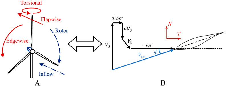
Figure 1. (A) Terminology for degrees of freedom of wind turbine blade and (B) velocity triangle of wind turbine section airfoil.
Figure 1B further shows the velocity triangle of blade section airfoil. Where,
2.1 Aerodynamic model
In the calculation of aerodynamic load, a model based on unsteady BEMT is constructed, which considers blade tip correction, hub loss, wake correction, and Leishman-Beddoes dynamic stall model to consider aerodynamic nonlinear characteristics. Compared with vortex theory methods (Sessarego et al., 2018) and computational fluid dynamics methods (Tran and Kim, 2015), the adoption of BEMT has significant advantages of high computational efficiency, and can ensure acceptable computational accuracy after introducing necessary amendments to the model. Therefore unsteady BEMT is selected in this study. Some key calculation formulas can be expressed as follows.
As shown in Figure 1B, the blade section velocity consists of incoming flow velocity, wind wheel rotation velocity, induced velocity and blade motion velocity, and the relationship among them can be given according to Equation 1:
The traditional BEMT is only applicable to quasi-steady problems, so the unsteady BEMT introduces the dynamic inflow model (Snel and Schepers, 1995) to be applicable to the calculation of unsteady problems, as shown in Equations 2, 3:
Where
2.2 Structural model
The structural module is solved by Geometrically Exact Beam Theory (GEBT). The GEBT can consider transverse shear and bending of the section, as well as large displacement and rotation, so it can capture the coupling effects between the six degrees of freedom of the beam, including extension, bending, shear and torsion. In GEBT, the motion governing equation can be expressed as Equations 4, 5:
Where
The constitutive equation can be expressed as Equations 6, 7:
Where
Where
2.3 IEA 15 MW wind turbine
In this study, the IEA 15 MW wind turbine (Gaertner et al., 2020) is taken as the research object. The blade length of this wind turbine is about 120 m, which is a typical long and flexible blade with strong nonlinear characteristics. Various studies on the aeroelastic and flutter characteristics of IEA 15 MW wind turbines have been accumulated (Qian et al., 2024; Loubeyres et al., 2022; Li et al., 2023; Lu et al., 2022). Table 1 shows some basic parameters of the IEA 15 MW wind turbine.
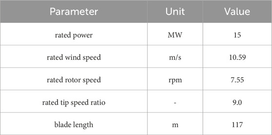
Table 1. Basic parameters of the IEA 15 MW wind turbine.
First of all, the vibration mode of the blade is calculated based on the condition that the rotor speed is 0 and there is no aerodynamic load. The results are shown in Table 2. In Table 2, the modal frequency calculation results of the aeroelastic model in this paper are compared with those in the literature, and it is found that the overall error between the modal frequencies is small, which verifies the accuracy of the aeroelastic model in this paper.
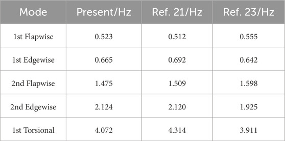
Table 2. Mode frequency of the IEA 15 MW wind turbine.
First of all, the vibration mode of the blade is calculated based on the condition that the rotor speed is 0 and there is no aerodynamic load. The results are shown in Table 2. In Table 2, the modal frequency calculation results of the aeroelastic model in this paper are compared with those in the literature, and it is found that the overall error between the modal frequencies is small, which verifies the accuracy of the aeroelastic model in this paper.
3 Results and discussion
3.1 Time domain analysis of wind turbine aeroelastic response
Figure 2A shows the tip vibration signal of the blades of IEA 15 MW wind turbine at a rotor speed of 5.5 rpm and a wind speed of 15.6 m/s. Under the working condition shown in Figure 3, in the initial stage of vibration, flutter energy has not accumulated, and blades mainly vibrate with rotation frequency under the influence of gravity. The vibration period is about 10.9 s, the flapwise amplitude is about 0.56 m, the edgewise amplitude is about 2.40 m, and the torsional amplitude is about 0.9°. Later, with the continuous input of aerodynamic energy, the amplitude gradually accumulates in an exponential form, and finally reaches a stable state of Limited Cycle Oscillation (LCO), which contains multiple frequency components. Finally, the flapwise amplitude is about 1.49m, the edgewise amplitude is about 5.40 m, and the torsional amplitude is about 13.1°. In addition, it can be seen from Figure 3 that during the gradual accumulation of amplitude, the average flapwise displacement decreases somewhat, reflecting the inherent load reduction characteristics of the blade itself.
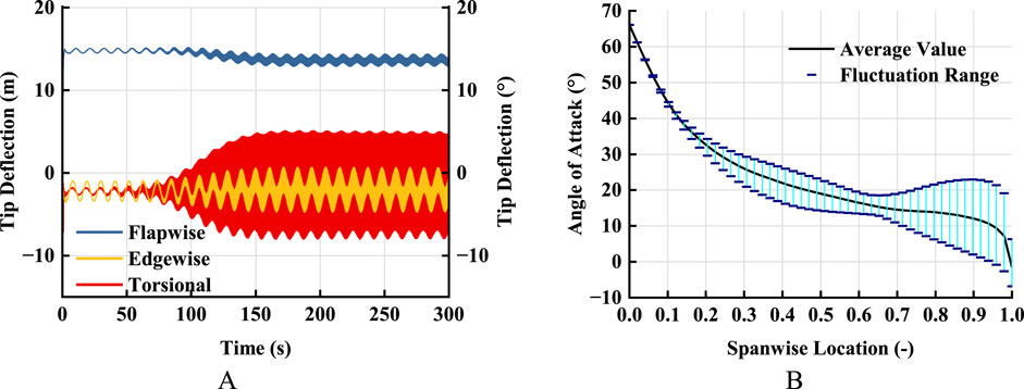
Figure 2. (A) Blade tip deflection and (B) spanwise distribution of Angle of attack (rotor speed 5.5 rpm, wind speed 15.6 m/s).
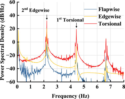
Figure 3. Spectrum of blade tip deflection (rotor speed 5.5 rpm, wind speed 15.6 m/s).
Figure 2B shows the distribution of angle of attack at each position of blade extension when flutter occurs at a rotor speed of 5.5 rpm and a wind speed of 15.6 m/s, including the average value and fluctuation range. As can be seen from the Figure, when the blade vibrates under this working condition, the local average angle of attack at the working section of the blade is roughly 10°–30°, and gradually decreases along the blade root to the blade tip. The fluctuation range of the angle of attack of each section of the working section is 0–30°. In the part below 65% blade spanwise location, the AOA is always greater than 12° and the fluctuation range is less than 10° when the blade is vibrating. In the part between 65 and 100% spanwise location, the fluctuation of the AOA is further enhanced. The fluctuation of the AOA reaches more than 20° in the section from 88% spanwise location to blade tip. Rapid and large fluctuations at high average AOA will result in significant nonlinear effects of aerodynamic force on the blade, which further enhances the nonlinear characteristics of aeroelastic response of the blade.
3.2 Frequency domain characteristic analysis of wind turbine aeroelastic response
Figure 3 shows the spectrum diagram of blade tip vibration signal when the rotor speed is 5.5 rpm and the wind speed is 15.6 m/s. The dominant frequency in the spectrum is 2.2 Hz, which represents the second edgewise mode. In addition, the first torsional mode natural frequency is close to the second harmonic of the second edgewise mode natural frequency, so it is concluded that the spectrum of each degree of freedom also contains significant first torsional mode natural frequency.
As can be seen from Figure 5, the inherent coupling characteristics of each degree of freedom in the blade structure are reflected in the consistency of each peak value of the spectrum of each degree of freedom, that is, the blade vibration in each degree of freedom is carried out at the same frequency. The difference of the frequency spectrum of each degree of freedom is mainly due to the high natural frequency of the first torsional mode, so the high-frequency component of the torsional spectrum is relatively strong.
3.3 Aerodynamic work analysis of wind turbine aeroelastic response
When the blade vibrates stably, the instantaneous aerodynamic power of each blade element and the aerodynamic work done per unit vibration period can be calculated according to Equations 9, 10:
Where
Figure 4 shows the spanwise distribution of aerodynamic work done per unit vibration period when the blade is vibrating stably. As can be seen from the Figure, the aerodynamic work of flapwise, edgewise and torsional degrees of freedom all have influences on flutter, and the flapwise and edgewise direction have stronger influences. Flutter is mainly affected by the parts above 20% blade spanwise location, and the aerodynamic work from the blade root to 20% blade spanwise location is almost negligible. In flapwise direction, the aerodynamic force of the whole blade is positive, and work in the blade tip area above 90% blade spanwise location accounts for the largest proportion. In edgewise direction, the positive aerodynamic work is performed at 20–57% blade spanwise location, the negative aerodynamic work is performed at 57–75% blade spanwise location, and the most important positive aerodynamic work is performed at the blade tip aera above 75% blade spanwise location. In torsional direction, negative aerodynamic work is performed in 63%–80% of the blade spanwise location, and positive aerodynamic work is performed in the rest area of the blade.
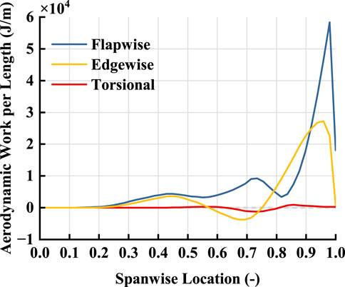
Figure 4. Spanwise distribution of single period aerodynamic work under stable vibration.
Figure 5 shows the instantaneous aerodynamic power at each degree of freedom within one blade rotation period after the blade reaches a stable LCO state when flutter occurs. Because the vibration frequency during flutter is much higher than the rotor rotation frequency, the signal in one blade rotation period nearly contains all the vibration characteristics. It can be seen from Figure 5 that the aerodynamic nonlinear factors and structural nonlinear factors together lead to significant nonlinear aerodynamic work development on the blade surface. In the Figure, the aerodynamic work near the tip of the blade fluctuates greatly, which is consistent with the large-period aerodynamic work near the tip of the blade in Figure 4.
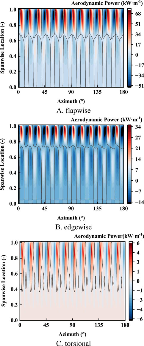
Figure 5. Development of aerodynamic power per rotation period during LCO. (A) flapwise. (B) edgewise. (C) torsional.
For further analysis of the development process of instantaneous aerodynamic power, in flapwise direction, as shown in Figure 5A, in the blade vibration process, the upper and lower sections of the blade alternately perform positive and negative work with the boundary of 65% blade spanwise location. The aerodynamic power fluctuation is the most severe in the 80%–98% blade spanwise location. In edgewise direction, as shown in Figure 5B, when the blade vibrates, the upper and lower sections of the blade alternately perform positive work and negative work at the boundary of 72% blade spanwise location, and the aerodynamic power fluctuation is the most severe at the 85%–98% blade spanwise location. In torsional direction, as shown in Figure 5C, the fluctuation of aerodynamic power mainly exists in the part above 40% blade spanwise location, and the 40%–100% blade spanwise location enters the positive aerodynamic power state almost simultaneously at some time, and then gradually exits from the blade root to the tip. In addition, Figure 5 indicates that the energy changes on all 3 degrees of freedom are tightly coupled. The positive and negative peaks of aerodynamic power in each degree of freedom appear synchronously, and the aerodynamic power fluctuation is basically the same frequency and phase.
Figure 6 show the phase trajectory of aerodynamic force at 69% and 94% blade spanwise location. It can be seen from the Figure that in the 69% blade spanwise location, in torsional direction, the phase trajectory is dominated by the counterclockwise ring, which corresponds to the local negative aerodynamic work. Due to the constant change of blade balance position under the action of gravity, the flapwise and edgewise direction do not show obvious phase trajectory loops, but it can be roughly judged that the clockwise and counterclockwise directions are respectively dominant, corresponding to the positive aerodynamic work in the flapwise direction and negative aerodynamic work in the edgewise direction. In the 90% blade spanwise location, the clockwise phase trajectory ring dominates the flapwise and edgewise direction, but the phase trajectory in the torsional direction shows the alternating characteristics of positive and negative work.
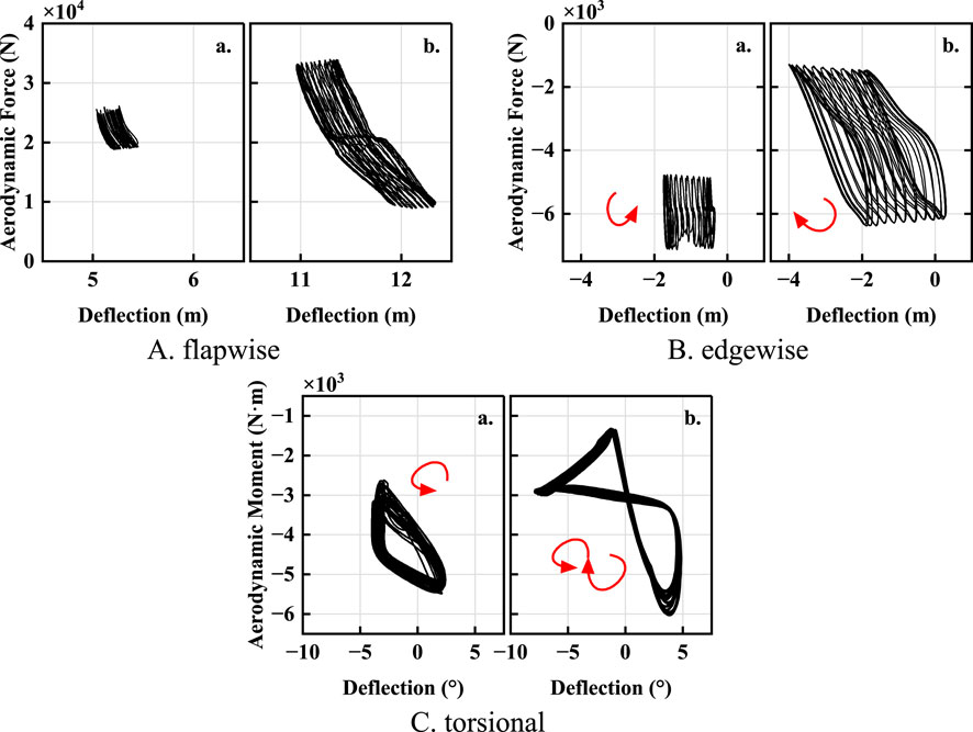
Figure 6. Phase trajectory of aerodynamic moment per rotation period during LCO (A) 69% spanwise; (B) 94% spanwise). (A) flapwise. (B) edgewise. (C) torsional.
4 Conclusion
Based on the aeroelastic model of wind turbine coupled with unsteady BEMT and GEBT, the flutter characteristics of IEA 15 MW wind turbine at low rotor speed are analyzed. The results show that the multi-degree-of-freedom coupling flutter of flapwise-edgewise-torsional degrees of freedom will occur at high wind speed at 73% rated speed. Because of the inherent bend-torsional coupling characteristics of the blade structure, the vibration spectrum of the blade in the three degrees of freedom is the same, including the edgewise natural frequency and the torsional natural frequency. The analysis of aerodynamic force and work shows that flutter is maintained by the joint action of flapwise, edgewise and torsional degrees of freedom, especially flapwise and edgewise direction. The analysis of instantaneous aerodynamic power further verifies the flapwise-edgewise-torsional coupling characteristics of energy during flutter. There is an obvious coupling phenomenon in the development of instantaneous aerodynamic power at each degree of freedom.
Data availability statement
The original contributions presented in the study are included in the article/supplementary material, further inquiries can be directed to the corresponding author.
Author contributions
LM: Writing – original draft, Writing – review and editing. MQ: Conceptualization, Data curation, Formal Analysis, Funding acquisition, Investigation, Methodology, Project administration, Resources, Software, Supervision, Validation, Visualization, Writing – review and editing. XZ: Conceptualization, Data curation, Formal Analysis, Funding acquisition, Investigation, Methodology, Project administration, Resources, Software, Supervision, Validation, Visualization, Writing – review and editing. XS: Conceptualization, Data curation, Formal Analysis, Funding acquisition, Investigation, Methodology, Project administration, Resources, Software, Supervision, Validation, Visualization, Writing – review and editing. SW: Conceptualization, Data curation, Formal Analysis, Funding acquisition, Investigation, Methodology, Project administration, Resources, Software, Supervision, Validation, Visualization, Writing – review and editing.
Funding
The author(s) declare that financial support was received for the research and/or publication of this article. The research is supported by China Three Gorges Corporation (202303058) and National Key Research and Development Project of China (2023YFB4203100). The funder was not involved in the study design, collection, analysis, interpretation of data, the writing of this article, or the decision to submit it for publication.
Conflict of interest
Authors LM, MQ, and XZ were employed by China Three Gorges Corporation.
The remaining authors declare that the research was conducted in the absence of any commercial or financial relationships that could be construed as a potential conflict of interest.
Generative AI statement
The author(s) declare that no Gen AI was used in the creation of this manuscript.
Publisher’s note
All claims expressed in this article are solely those of the authors and do not necessarily represent those of their affiliated organizations, or those of the publisher, the editors and the reviewers. Any product that may be evaluated in this article, or claim that may be made by its manufacturer, is not guaranteed or endorsed by the publisher.
References
Bortolotti, P., Chetan, M., Branlard, E., Jonkman, J., Platt, A., Slaughter, D., et al. (2024). Wind turbine aeroelastic stability in OpenFAST. J. Phys. Conf. Ser. IOP Publ. 2767 (2), 022018. doi:10.1088/1742-6596/2767/2/022018
Chen, G., Chen, J., and Pang, X. P. (2020). Analysis on bending-bending coupled aeroelastic response of horizontal axiswind turbine blades. Acta energiae solaris sin. 41 (05), 70–76. doi:10.19912/j.0254-0096.2020.05.011
Farsadi, T., and Kayran, A. (2021). Classical flutter analysis of composite wind turbine blades including compressibility. Wind Energy 24 (1), 69–91. doi:10.1002/we.2559
Gaertner, E., Rinker, J., Sethuraman, L., Zahle, F., Anderson, B., Barter, G., et al. (2020). IEA wind TCP task 37: definition of the IEA 15-megawatt offshore reference wind turbine. Golden, CO (United States): National Renewable Energy Lab. NREL.
Griffith, D. T., and Ashwill, T. D. (2011). The sandia 100-meter all-glass baseline wind turbine blade: SNL100-00. Springfield, VA: Sandia National Laboratories, 1–62.
Hansen, M. H. (2007). Aeroelastic instability problems for wind turbines. Wind Energy Int. J. Prog. Appl. Wind Power Convers. Technol. 10 (6), 551–577. doi:10.1002/we.242
Hayat, K., de Lecea, A. G. M., Moriones, C. D., and Ha, S. K. (2016). Flutter performance of bend–twist coupled large-scale wind turbine blades. J. Sound Vib. 370, 149–162. doi:10.1016/j.jsv.2016.01.032
Li, B., Tian, D., Wu, X., Meng, H., and Su, Y. (2023). The impact of bend–twist coupling on structural characteristics and flutter limit of ultra-long flexible wind turbine composite blades. Energies 16 (15), 5829. doi:10.3390/en16155829
Li, Y. J., and Wang, T. G. (2017). Dynamic analysis of wind turbine blade based on different references. Acta energiae solaris sin. 38 (01), 16–22. doi:10.19912/j.0254-0096.2017.01.003
Loubeyres, J., Pfister, J. L., Blondel, F., and Guy, N. (2022). Stall flutter instabilities on the IEA-15 reference wind turbine in idling conditions: code-to-code comparisons and physical analyses. J. Phys. Conf. Ser. IOP Publ. 2265 (3), 032019. doi:10.1088/1742-6596/2265/3/032019
Lu, M. M., Ke, S., Wu, H., Gao, M. e., Tian, W. x., and Wang, H. (2022). A novel forecasting method of flutter critical wind speed for the 15 MW wind turbine blade based on aeroelastic wind tunnel test. J. Wind Eng. Industrial Aerodynamics 230, 105195. doi:10.1016/j.jweia.2022.105195
Meehan, P. A. (2023). Prediction and suppression of chaos following flutter in wind turbines. Nonlinear Dyn. 111 (24), 22153–22176. doi:10.1007/s11071-023-08841-9
Pourazarm, P., Modarres-Sadeghi, Y., and Lackner, M. (2016). A parametric study of coupled-mode flutter for MW-size wind turbine blades. Wind Energy 19 (3), 497–514. doi:10.1002/we.1847
Qian, X., Zhang, B., Gao, Z., Wang, T., Zhang, L., and Li, Y. (2024). Flutter limit optimization of offshore wind turbine blades considering different control and structural parameters. Ocean. Eng. 310, 118558. doi:10.1016/j.oceaneng.2024.118558
Sessarego, M., Ramos-Garcia, N., and Shen, W. Z. (2018). Analysis of winglets and sweep on wind turbine blades using a lifting line vortex particle method in complex inflow conditions. J. Phys. 1037, 022021. doi:10.1088/1742-6596/1037/2/022021
Shakya, P., Sunny, M. R., and Maiti, D. K. (2022). Nonlinear flutter analysis of a bend-twist coupled composite wind turbine blade in time domain. Compos. Struct. 284, 115216. doi:10.1016/j.compstruct.2022.115216
Snel, H., and Schepers, J. G. (1995). Joint investigation of dynamic inflow effects and implementation of an engineering method. Petten, Netherlands: Energy research Centre of the Netherlands ECN.
Tran, T. T., and Kim, D. H. (2015). The platform pitching motion of floating offshore wind turbine: a preliminary unsteady aerodynamic analysis. J. Wind Eng. Industrial Aerodynamics 142, 65–81. doi:10.1016/j.jweia.2015.03.009
Wang, L., Liu, X. W., and Kolios, A. (2016). State of the art in the aeroelasticity of wind turbine blades: aeroelastic modelling. Renew. Sustain. Energy Rev. 64, 195–210. doi:10.1016/j.rser.2016.06.007
Wang, Q., Sprague, M. A., Jonkman, J., Johnson, N., and Jonkman, B. (2017). BeamDyn: a high-fidelity wind turbine blade solver in the FAST modular framework. Wind Energy 20 (8), 1439–1462. doi:10.1002/we.2101
Zhang, Y. (2022). Research on vibration and flutter characteristics of large wind turbine blade. Beijing: North China Electric Power University.
Keywords: wind turbine, aeroelasticity, multi-degree-of-freedom coupling, flutter, blade element momentum theory
Citation: Ma L, Qin M, Zhang X, Shen X and Wang S (2025) Analysis of flutter characteristics of ultra-large horizontal axis wind turbine blades at low rotor speed. Front. Energy Res. 13:1586142. doi: 10.3389/fenrg.2025.1586142
Received: 02 March 2025; Accepted: 21 April 2025;
Published: 15 May 2025.
Edited by:
Agnimitra Biswas, National Institute of Technology, IndiaCopyright © 2025 Ma, Qin, Zhang, Shen and Wang. This is an open-access article distributed under the terms of the Creative Commons Attribution License (CC BY). The use, distribution or reproduction in other forums is permitted, provided the original author(s) and the copyright owner(s) are credited and that the original publication in this journal is cited, in accordance with accepted academic practice. No use, distribution or reproduction is permitted which does not comply with these terms.
*Correspondence: Shen Xin, c2hlbnhpbkBzanR1LmVkdS5jbg==