 Lu Ma
Lu Ma Yijia Li
 Le Zhou
 Hao Guo
 Xin Shen
 Zhaohui Du2,3
- 1China Three Gorges Corporation, Wuhan, China
- 2School of Mechanical Engineering, Shanghai Jiao Tong University, Shanghai, China
- 3Shanghai Non-carbon Energy Conversion and Utilization Institute, Shanghai, China
Introduction: Swept blades can achieve effective load reduction, thereby improving the operational performance of wind turbines. To investigate the impact of hundred-meter-level swept blades on the load characteristics of wind turbines, this paper takes the IEA-15 MW wind turbine as the subject.
Methods: Based on the free-wake lifting line theory model and the geometrically exact beam theory model, the load characteristics of straight blades and swept blades under rated conditions are compared.
Results and discussion: The results show that swept blades undergo greater torsional deflection, thereby reducing the effective angle of attack of the blades and achieving load reduction. The influence of different sweep parameters on load characteristics is also discussed. The study finds that the load reduction effects of the sweep starting point and sweep index are similar, while the load reduction effect of the sweep displacement is the most significant, and it becomes more pronounced as the sweep displacement increases. Additionally, under yaw conditions, as the sweep displacement increases, the gradually increasing torsional deflection and the gradually decreasing amplitude of the flapwise speed fluctuation lead to a downward trend in both the mean and fluctuation amplitude of the angle of attack.
1 Introduction
Floating offshore wind turbines operate in complex, variable, and unpredictable marine environments throughout the year (Yang et al., 2020; Yang et al., 2023a; Yang et al., 2023b). Under the combined effects of wind, waves, and currents, these turbines are not only influenced by unsteady inflow but also by the periodic motion of the floating platform and the additional acceleration caused by the reciprocating bending deflection of the blades. These factors intensify blade load fluctuations and deflection, reducing the fatigue life of the blades. Therefore, effective load control of floating wind turbine blades is crucial for the stable and safe operation of wind turbines (Shen et al., 2021; Zhang et al., 2020).
Current load reduction strategies for wind turbines can be categorized into active and passive control methods. In addition to the conventional pitch control, emerging active load reduction techniques in recent years primarily involve installing mechanical actuators to modify the airfoil shape or angle of attack, thereby controlling blade loads (Zhang et al., 2014; Han et al., 2023; Qi et al., 2022). Passive load reduction is achieved by altering the blade’s geometric structure or ply orientation to induce bend-twist coupling. This design allows overloaded blades to naturally twist toward a nose-down direction during bending deflection, reducing the angle of attack and partially shedding loads. Compared to active load control, passive load reduction is easier to implement in engineering practice. There are two main approaches to achieve passive load reduction: blade sweep (Larwood et al., 2014b; Stäblein et al., 2016; Pavese et al., 2017; Chen et al., 2019a) and asymmetric composite layup. Among them, blade sweep does not require changes to the blade’s layup design, resulting in relatively lower design complexity.
Many studies have concentrated on the design of the swept blade for load reduction of the wind turbine. Larwood et al. (2014b) conducted parametric and scaling studies on swept blades for wind turbines, using the CurveFAST aeroelastic code. They analyzed a 750 kW turbine and extended the study to 1.5 MW, 3 MW, and 5 MW turbines. The results showed that tip sweep had the most significant impact on load reduction and energy production. Successful designs were achieved for 1.5 MW and 3 MW turbines, but the 5 MW turbine exhibited twist instability at high wind speeds, suggesting limitations for larger turbines. Stäblein et al. (2016) used eigenvalue analysis and the HAWCStab2 tool to study the effects of bend-twist coupling on the aeroelastic properties of the DTU 10 MW wind turbine. They introduced material-based coupling through cross-sectional stiffness matrices and found that edge-twist coupling increased damping for feathering and decreased it for stall. Flap-twist coupling increased frequency and reduced damping for feathering, while the opposite occurred for stall. The study confirmed load alleviation benefits but highlighted stability challenges, particularly for edgewise modes. Pavese et al. (2017) used a multidisciplinary design optimization (MDO) framework to optimize a 10-MW wind turbine blade, incorporating sweep as a design variable. The study employed a multi-fidelity approach, combining steady-state and frequency-domain models to estimate loads. The optimization aimed to minimize blade mass and blade root flapwise fatigue damage equivalent loads (DELs). The results demonstrated that including sweep in the MDO process allowed for further reductions in blade mass (2%–3%) and flapwise fatigue DELs (8%) compared to straight blades. The study concluded that swept blades could passively control loads, improving overall turbine performance. Chen et al. (2019a) employed an advanced aeroelastic model based on the Free Wake Vortex Lattice Model (FWVLM) and Geometrically Exact Beam Theory (GEBT) to study the potential of backward swept blades in mitigating load variations caused by vertical wind shear. The study focused on the NREL 5-MW reference wind turbine and compared the performance of baseline and swept blades. The results showed that backward swept blades effectively reduced the amplitude of flapwise root moment variations and mean rotor yaw and tilt moments, albeit at the cost of increased blade root torsion moment. The study concluded that backward swept blades could passively alleviate fatigue loads in shear wind conditions. Thangavelu et al. (2021) conducted aeroelastic performance analysis using CFD and FEA to investigate the effect of yaw angle on HAWT swept blades. The study compared swept and un-swept blades under yaw angles of 0°, 10°, 30°, and 60° at a wind speed of 10 m/s. The results indicated that yaw error negatively affected both swept and un-swept blades, but swept blades exhibited better performance in terms of higher rotor power and lower deflection. The study concluded that swept blades offer improved stability and power generation under yaw conditions compared to un-swept blades. McWilliam et al. (2022) introduced a Post-Optimum Sensitivity Analysis (POSA) method to study the impact of design constraints and parameters on wind turbine blade performance. They used statistical techniques to automatically tune numerical gradients and applied this method to swept wind turbine blades. The study found that introducing sweep reduces sensitivity to blade root flap-wise bending moments but increases sensitivity to material failure and blade root torsion moments. The POSA method was shown to be effective in identifying key design drivers without requiring multiple optimization runs.
The aforementioned studies have confirmed the load reduction effectiveness of swept blades and laid a foundation for further research in this area. However, most of these studies focused on 5 MW wind turbines, which do not provide sufficient data support for the development of current 15 MW or even 20 MW wind turbines. Therefore, this paper investigates the load reduction characteristics of swept blades on the IEA-15 MW wind turbine under unsteady operating conditions and examines the impact of different sweep parameters on the load reduction performance of the blades.
2 Methodology and research object
2.1 Aeroelastic method
This paper investigates the load reduction characteristics of swept blades for a 15 MW wind turbine under unsteady operating conditions, utilizing the lifting line free vortex wake model and the geometrically exact beam model. In previous work, these models were discussed and compared in detail. To ensure the completeness of this paper, a brief overview of these models is provided in this section. For more detailed information on the models, please refer to the relevant literatures (Sebastian and Lackner, 2012; Shen et al., 2018; Bauchau, 2011; Hodges, 2009; Chen et al., 2019b).
The free vortex wake model can accurately predict the load characteristics of wind turbines under unsteady operating conditions. It also accounts for the dynamic evolution of the wake and its impact on the induced velocity at the rotor plane. The governing equation for the wake evolution is given by Equation 1.
where
The geometrically exact beam model accounts for the bend-twist coupling characteristics and nonlinear deflections of blades with swept designs. The governing equation of this model is given by Equation 2.
where,
2.2 Research object
This study selects the IEA-15 MW wind turbine as the research object. The IEA-15 MW is an upwind, horizontal-axis wind turbine featuring a rotor diameter of 240 m, a hub height of 150 m, and blade length of 117 m. The turbine is mounted on a monopile foundation with a diameter of 10 m, suitable for a water depth of 30 m and a burial depth of 45 m below the seabed. The cut-in and cut-out wind speeds are 3 m/s and 25 m/s respectively, and the rated wind speed is 10.59 m/s. The rated rotational speed is 7.55 rpm, and the design tip-speed ratio is 9. Basic parameters of the IEA-15 MW wind turbine are listed in Table 1 (Gaertner et al., 2020).
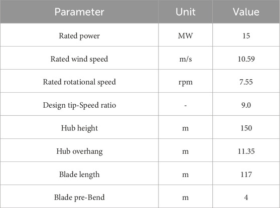
Table 1. Basic parameters of the IEA-15 MW wind turbine.
3 Results and discussion
3.1 Definition method of swept blade
Swept blade can effectively alter the aerodynamic forces acting on the blades by adjusting their geometric shape, gradually inclining from the root to the tip, thereby enhancing the aerodynamic performance and structural stability of wind turbines. As the scale of wind turbines continues to expand, the design of swept blades has become an important strategy for optimizing aerodynamic performance and reducing load fluctuations in large wind turbines. Based on the bend-twist coupling characteristics of swept blades, passive load reduction control for unsteady loads can be achieved, reducing the amplitude of load fluctuations. Compared to active pitch control, passive control offers advantages such as rapid response and no reliance on actuators. Larwood et al. (2014a) found that swept blades can effectively reduce the fatigue loads on the blades, improve wind turbine performance, and extend the fatigue life of the blades.
The geometric shape of the swept blades established in this paper follows an exponential form, and the specific formula is as Equation 3:
In the formula,
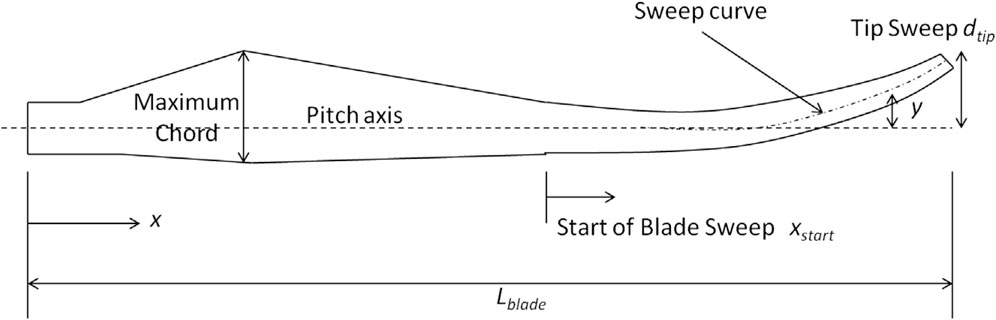
Figure 1. Schematic diagram of swept blade parameters (Larwood et al., 2014a).
3.2 Comparison between straight blade and swept blade
To thoroughly analyze the load reduction mechanism of swept blades, this section compares and analyzes the load characteristics, blade deflection, and sectional angle of attack differences between the straight blade (i.e., the IEA-15 MW prototype blade) and a specific swept blade under rated conditions. The swept blade in question has a sweep index of 2, a sweep starting point at 0.2 R, and a sweep displacement of 2 m. Table 2 lists the mean values and fluctuation amplitudes of the rotor power, thrust, and root moments for both the straight blade and the swept blade under rated conditions (namely 10.59 m/s and 7.55 rpm). As the present study focus on the aeroelastic performance under unsteady condition of the IEA-15 MW wind turbine, the servo control is not considered in the present study.
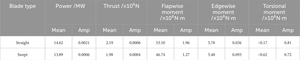
Table 2. Mean and amplitude of loads for the straight and swept blades under rated conditions.
The results show that the swept blade design effectively reduces the mean values and fluctuation amplitudes of the rotor loads, as well as the mean values and fluctuation amplitudes of the flapwise and edgewise moments at the blade root. However, the absolute mean value of the torsional moment increases significantly. Specifically, the mean values of power and thrust decrease by approximately 4.99% and 9.59%, respectively, while the mean values of the flapwise and edgewise moments decrease by approximately 11.98% and 5.19%, respectively. In contrast, the mean value of the torsional moment increases by approximately 264.71%.
Figure 2 presents the contour plots of the normal thrust distribution with respect to the azimuth angle for both the straight blade and the swept blade under rated conditions. The results indicate that the normal thrust distribution on the rotor plane of the straight blade is significantly greater than that of the swept blade, particularly in the spanwise region from 60% to 90%, where the difference is most pronounced. Due to the concentrated and uneven distribution of radial aerodynamic loads on the straight blade, larger loads are generated at the blade root, thereby exacerbating the fatigue loads at the root. In comparison to the straight blade, the swept blade exhibits a smaller mean normal thrust and a more uniform distribution of radial aerodynamic loads. This demonstrates that the swept design effectively reduces the peak normal thrust and the non-uniformity of the radial aerodynamic load distribution on the blade.
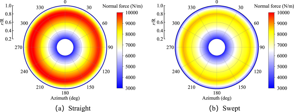
Figure 2. Contour of normal thrust with azimuth angle for the two types of blades under rated conditions. (a) Straight (b) Swept.
Figure 3 presents the contour plots of blade deflection with respect to the azimuth angle for both the straight blade and the swept blade under rated conditions. It can be observed that, due to the effective reduction of normal thrust by the swept design, the flapwise deflection of the swept blade is significantly smaller than that of the straight blade, particularly in the tip region (r/R = 0.9∼1.0), where this characteristic is most pronounced. Primarily influenced by gravity, the difference in edgewise deflection between the straight blade and the swept blade is relatively small. At the 90° azimuth angle, the edgewise deflection is larger due to the tangential force aligning with the direction of gravity, while at the 270° azimuth angle, the edgewise deflection is smaller as the tangential force opposes the direction of gravity. The torsional deflection of the swept blade is significantly greater than that of the straight blade, with the difference becoming increasingly evident in the spanwise region from 60% to 100%. Additionally, the negative value of torsional deflection indicates that the blade undergoes torsional deflection in the direction of reducing the angle of attack. Therefore, compared to the straight blade, the swept blade exhibits more significant torsional deflection, leading to a reduction in the effective angle of attack and thereby achieving load reduction.
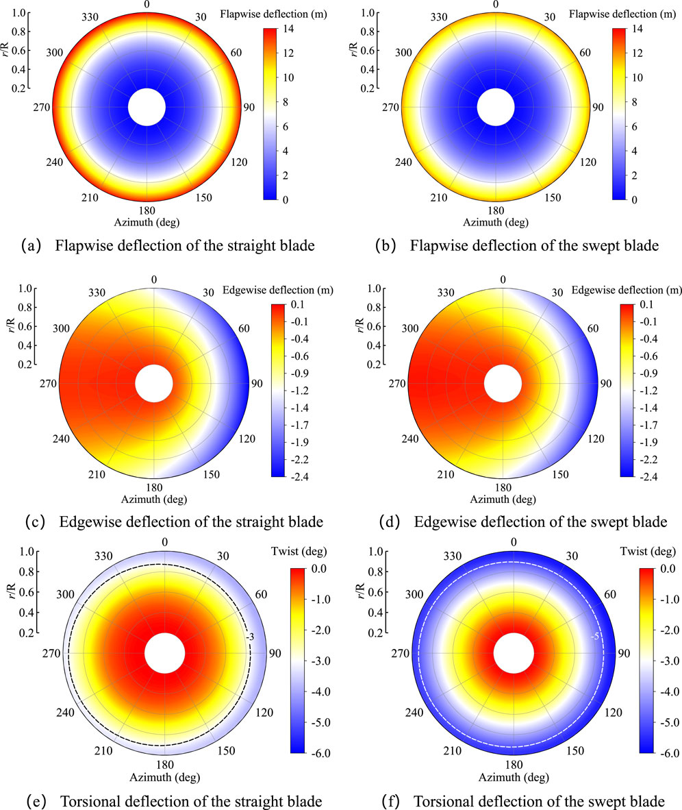
Figure 3. Contour of deflection with azimuth angle for the two types of blades under rated conditions. (a) Flapwise deflection of the straight blade (b) Flapwise deflection of the swept blade (c) Edgewise deflection of the straight blade (d) Edgewise deflection of the swept blade (e) Torsional deflection of the straight blade (f) Torsional deflection of the swept blade.
To further investigate the influence of blade torsional deflection on the angle of attack, Figure 4 presents the spanwise amplitude distributions of the angle of attack and torsional deflection for both the straight blade and the swept blade. The results show that, compared to the straight blade, the swept blade exhibits a reduction in both the mean value and fluctuation amplitude of the angle of attack, with the mean value decreasing significantly. At the same time, the mean value of torsional deflection for the swept blade increases notably, while its fluctuation amplitude decreases significantly. Therefore, the swept design, through its unique bend-twist coupling characteristics, induces greater torsional deflection in the blade under aerodynamic loads, thereby reducing the effective angle of attack and achieving load reduction for both the blade and the rotor. Additionally, the smaller fluctuation amplitudes of torsional deflection and angle of attack in the swept blade indicate that the swept design can effectively enhance the stability of the blade’s dynamic response, thereby extending the operational lifespan of the wind turbine. However, it is noteworthy that the torsional moment at the root of the swept blade increases significantly, which requires careful consideration and trade-offs during the design process of swept blades.
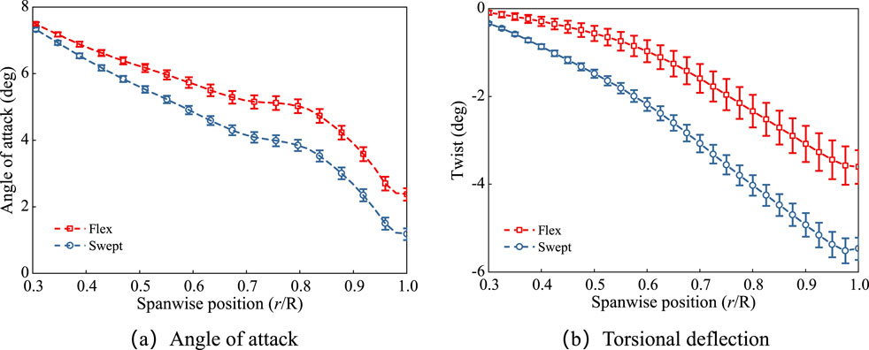
Figure 4. Angle of attack and torsional deflection spanwise amplitude under rated conditions. (a) Angle of attack (b) Torsional deflection.
3.3 Discussion on the influence of different sweep parameters
The swept blade adjusts the aerodynamic loads by optimizing the blade’s geometric shape. Its bending-torsion coupling characteristics significantly enhance the impact of torsional deflection on the angle of attack, thereby achieving a better load reduction effect. Therefore, for large wind turbines, a reasonable swept design can effectively improve the stability of the wind turbine, and the discussion and analysis of the swept parameters are of great significance. To comprehensively analyze the impact of different swept parameters on the wind turbine’s load characteristics, this section selects an unsteady operating condition with a yaw angle of 40° as the inflow environment. Based on a swept blade with a sweep index of 2, a sweep starting position of 0.2 R, and a sweep displacement of 2 m, three swept parameters are changed to thoroughly investigate the influence of each parameter on the wind turbine’s load performance.
Different sweep indices imply differences in the variation of the blade’s swept shape along the spanwise direction. A lower sweep index results in a more gradual sweep shape, while a higher sweep index leads to a steeper sweep shape. To deeply analyze the impact of the sweep index on the load reduction effect of flexible blades and wind turbine loads, a comparative design scheme based on the blade’s geometric sweep parameters was proposed. In the study, the sweep start position was fixed at 0.2 R, and the sweep displacement was fixed at 2 m. Different swept blades were constructed by adjusting the sweep index (values of 2, 3, 4, and 5). Figure 5 gives the bar charts of the mean and amplitude of the wind turbine loads under different sweep index conditions with a yaw angle of 40°. It can be observed that as the sweep index increases, the mean thrust of the wind turbine increases, while the mean tilt moment and yaw moment decrease. When the sweep index increases from 2 to 4, both the mean wind turbine power and thrust show a downward trend, and the fluctuation amplitude of the tilt and yaw moments also decreases. These changes are more significant when the sweep index increases from 2 to 4. However, when the sweep index increases from 4 to 5, both the mean wind turbine power and thrust, as well as the fluctuation amplitudes of the tilt and yaw moments, show slight increases. Additionally, the fluctuation amplitude of the wind turbine power does not show a clear regular trend with the increase in the sweep index, reaching its minimum value at a sweep index of 3.
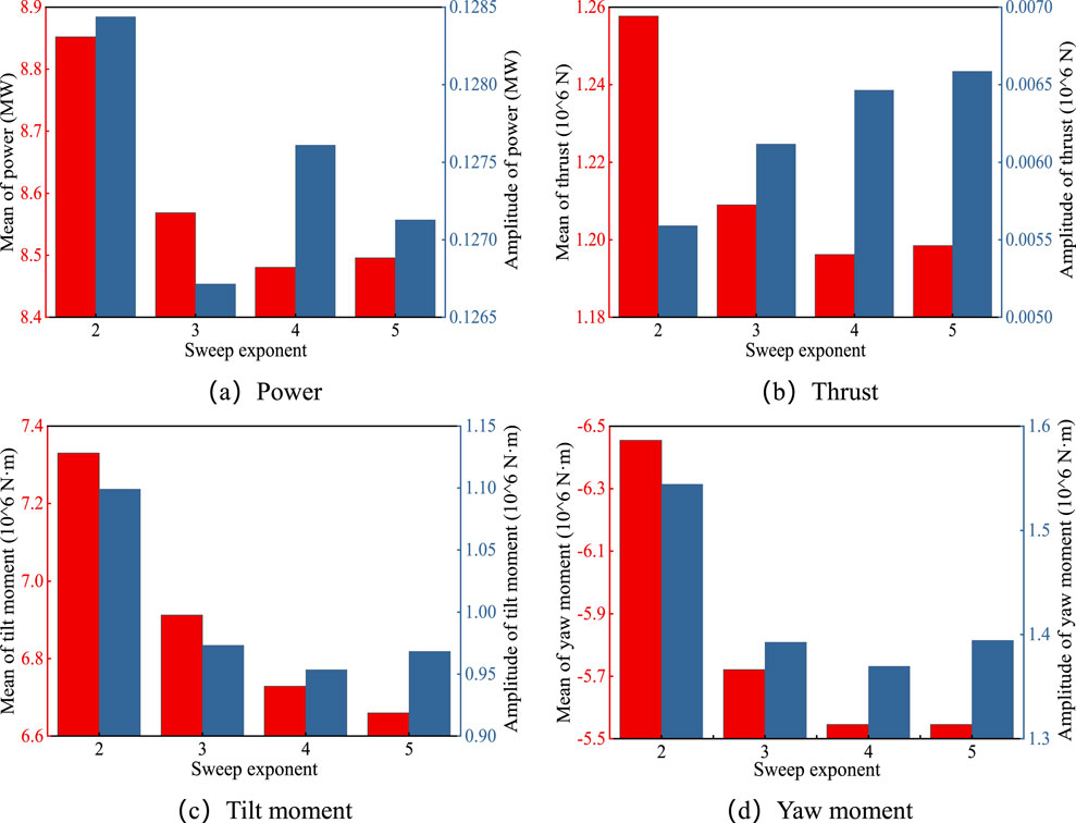
Figure 5. Bar chart of the mean amplitude of wind turbine loads under different sweep indices. (a) Power (b) Thrust (c) Tilt moment (d) Yaw moment.
Figure 6 gives the distribution of the mean and fluctuation amplitude of the torque at the blade root under different sweep indices with a yaw angle of 40°. It can be observed that when the sweep index increases from 2 to 3, the mean flapwise moment significantly decreases, while the mean tilt moment slightly decreases, and the fluctuation amplitudes of both decrease slightly. When the sweep index increases from 3 to 5, the mean values and fluctuation amplitudes of both the flapwise moment and tilt moment change little. The difference in the mean values of the flapwise and tilt moments at sweep indices 2 and 5 is approximately 2.49 × 10⁶ N·m and 0.14 × 10⁶ N·m, respectively. Additionally, the absolute value of the mean torsional moment gradually decreases with an increase in the sweep index. The fluctuation amplitude of the torsional moment decreases slightly as the sweep index increases from 2 to 3, and from 3 to 5, the changes in amplitude become consistent. The difference in the mean torsional moment at sweep indices 2 and 5 is approximately 0.21 × 10⁶ N·m.
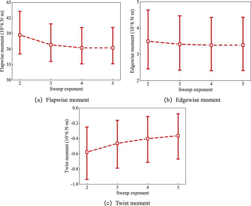
Figure 6. Torque fluctuation amplitude at the blade root under different sweep indices. (a) Flapwise moment (b) Edgewise moment (c) Twist moment.
The sweep start position refers to the radial location at which the blade’s swept shape begins to change. Different sweep start positions mean that the radial range of the blade involved in the sweep design differs, leading to variations in the blade’s bending-torsion coupling characteristics. Similar to the approach used to discuss the sweep index, this study designs multiple comparative schemes. By fixing the sweep index at 2 and the sweep displacement at 2 m, different swept blades were designed by adjusting the sweep start position (at 0.2 R, 0.3 R, 0.4 R, and 0.5 R along the span). The impact of these changes on blade loads was analyzed under yaw conditions. Figure 7 presents the bar charts of the mean and amplitude of the wind turbine loads under different sweep start positions. It can be observed that as the sweep start position increases, the mean wind turbine power and thrust gradually decrease, while the fluctuation amplitude of the wind turbine thrust significantly increases. The wind turbine power gradually decreases within the sweep start position range of 0.1 R–0.3 R, but significantly increases at 0.4 R, showing no clear regularity. The mean and fluctuation amplitudes of the wind turbine tilt moment and yaw moment significantly decrease as the sweep start position increases, indicating that increasing the sweep start position can effectively reduce the torque loads on the wind turbine.
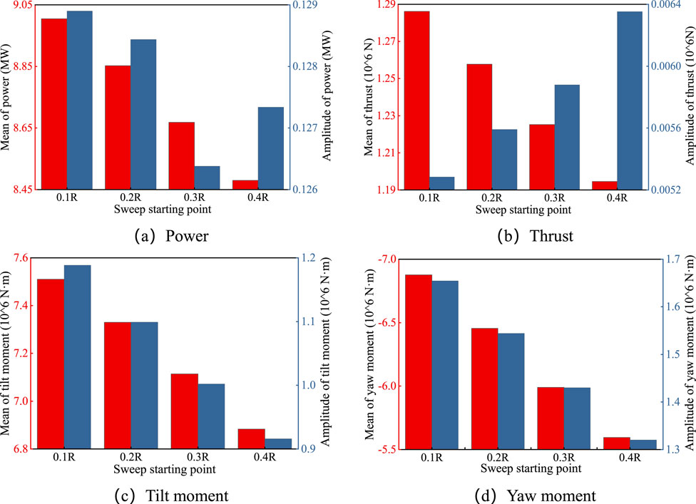
Figure 7. Bar chart of the mean amplitude of wind turbine loads at different sweep starting positions. (a) Power (b) thrust (c) tilt moment (d) yaw moment.
Figure 8 shows the effect of different sweep start positions on the mean and fluctuation amplitude of the torque at the blade root under a yaw angle of 40°. The results indicate that as the sweep start position increases, the mean flapwise moment at the blade root decreases significantly, and the fluctuation amplitude slightly decreases. The difference in the mean flapwise moment at sweep start positions of 0.1 R and 0.4 R is approximately 3.6 × 10⁶ N·m. The mean and fluctuation amplitude of the edgewise moment at the blade root show a slight decreasing trend. The difference in the mean edgewise moment at sweep start positions of 0.1 R and 0.4 R is approximately 0.23 × 10⁶ N·m. The absolute value of the mean torsional moment and its fluctuation amplitude gradually decrease, with the change in the fluctuation amplitude being relatively small. At sweep start positions of 0.1 R and 0.4 R, the difference in the mean torsional moment is approximately 0.16 × 10⁶ N·m.
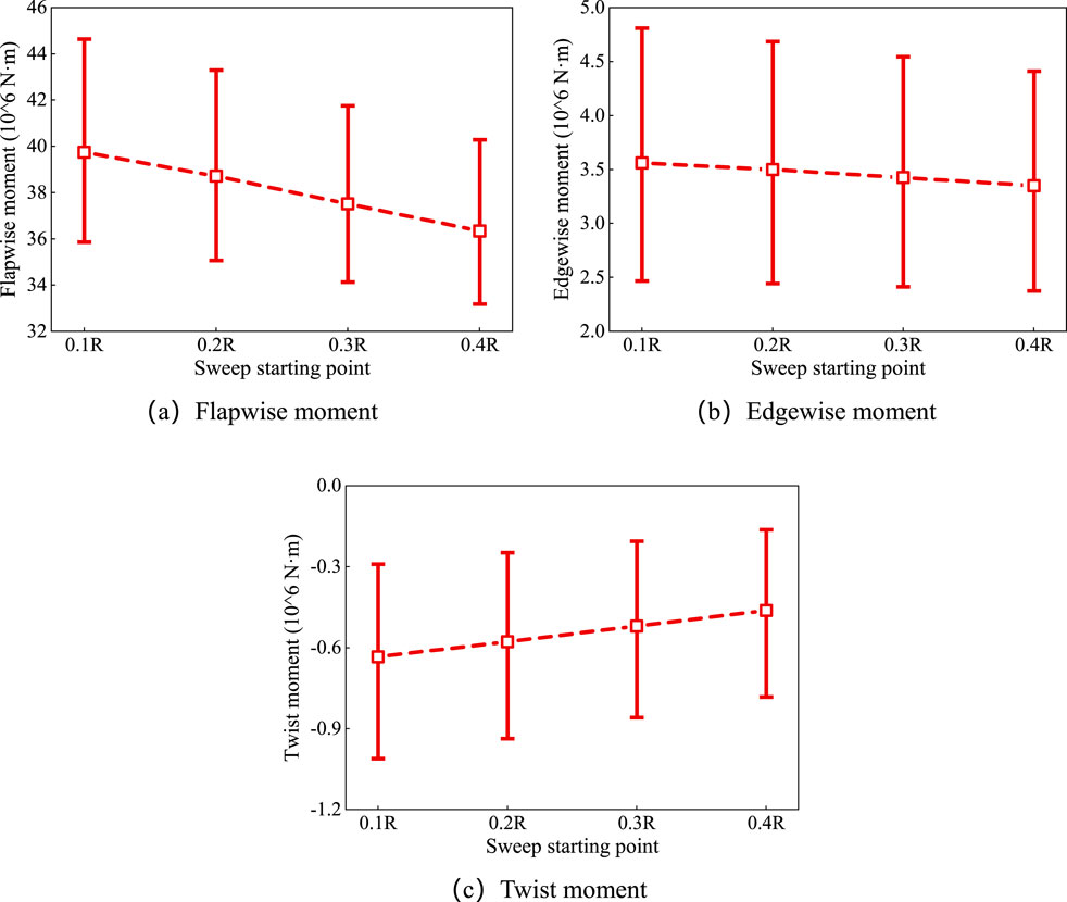
Figure 8. Torque fluctuation amplitude at the root under different starting positions. (a) Flapwise moment (b) edgewise moment (c) twist moment.
The sweep displacement refers to the offset of the blade axis in the direction of the airfoil’s trailing edge. Different sweep displacements represent variations in the blade’s sweep amplitude and shape, thus affecting the aerodynamic load distribution characteristics of the blade. In this study, a method similar to the previous approach is used, with the sweep index fixed at 2 and the sweep start position at 0.2 R. Different swept blade shapes are designed by changing the sweep displacement (2 m, 4 m, 6 m, 8 m, and 10 m), and the impact on blade loads is analyzed under yaw conditions. Similarly, the effect of different sweep displacements on wind turbine and blade loads was analyzed under a yaw angle of 40°. Figure 9 presents the bar charts of the mean and fluctuation amplitude of the wind turbine loads under different sweep displacements. The results show that as the sweep displacement increases, the mean and fluctuation amplitudes of wind turbine power, tilt moment, and yaw moment all decrease significantly. The mean thrust of the wind turbine gradually decreases with the increase in sweep displacement, while its fluctuation amplitude shows a continuous increasing trend. However, the fluctuation amplitude of wind turbine thrust is relatively small compared to its mean value and can be considered negligible in terms of overall impact. Overall, as the sweep displacement increases, both the mean and fluctuation amplitude of the wind turbine loads show a decreasing trend, demonstrating a more significant load reduction effect.
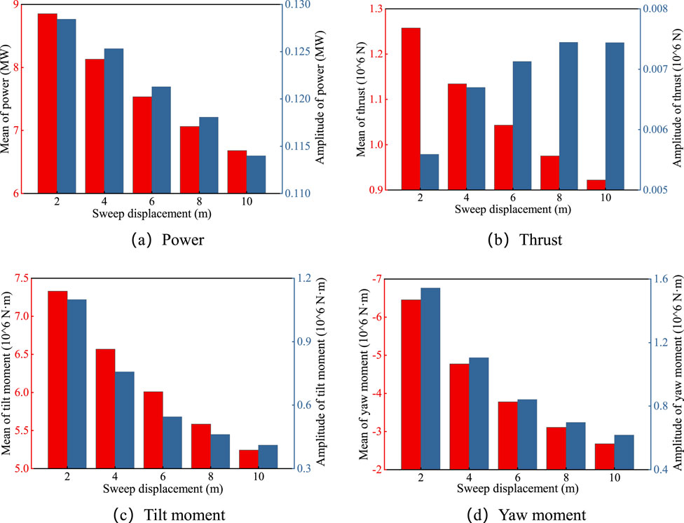
Figure 9. Bar chart of the mean amplitude of wind turbine loads under different sweep displacements. (a) Power (b) Thrust (c) Tilt moment (d) Yaw moment.
Figure 10 shows the effect of different sweep displacements on the mean and fluctuation amplitude of the torque at the blade root under yaw conditions. From the chart, it can be observed that as the sweep displacement increases, both the mean and fluctuation amplitude of the blade root flapwise moment decrease. Specifically, at sweep displacements of 2 m and 10 m, the difference in the mean flapwise moment is approximately 12.41 × 10⁶ N·m, and the difference in the fluctuation amplitude is approximately 4.91 × 10⁶ N·m. The mean and fluctuation amplitude of the edgewise moment at the blade root also gradually decrease with the increase in sweep displacement. When the sweep displacement increases from 2 m to 10 m, the mean edgewise moment decreases by approximately 0.87 × 10⁶ N·m, and the fluctuation amplitude decreases by approximately 0.91 × 10⁶ N·m. Additionally, as the sweep displacement increases, the absolute value of the mean torsional moment at the blade root increases significantly, indicating a more pronounced effect of torsional moment at the blade root. Its fluctuation amplitude shows a slow decreasing trend. From a sweep displacement of 2 m–10 m, the absolute value of the mean torsional moment increases by approximately 0.77 × 10⁶ N·m, while the fluctuation amplitude decreases by about 0.13 × 10⁶ N·m. The results show that sweep displacement has a significant impact on the torque characteristics at the blade root. As the sweep displacement increases, the swept blade effectively reduces the flapwise and edgewise moments at the blade root but leads to a significant increase in the torsional moment.
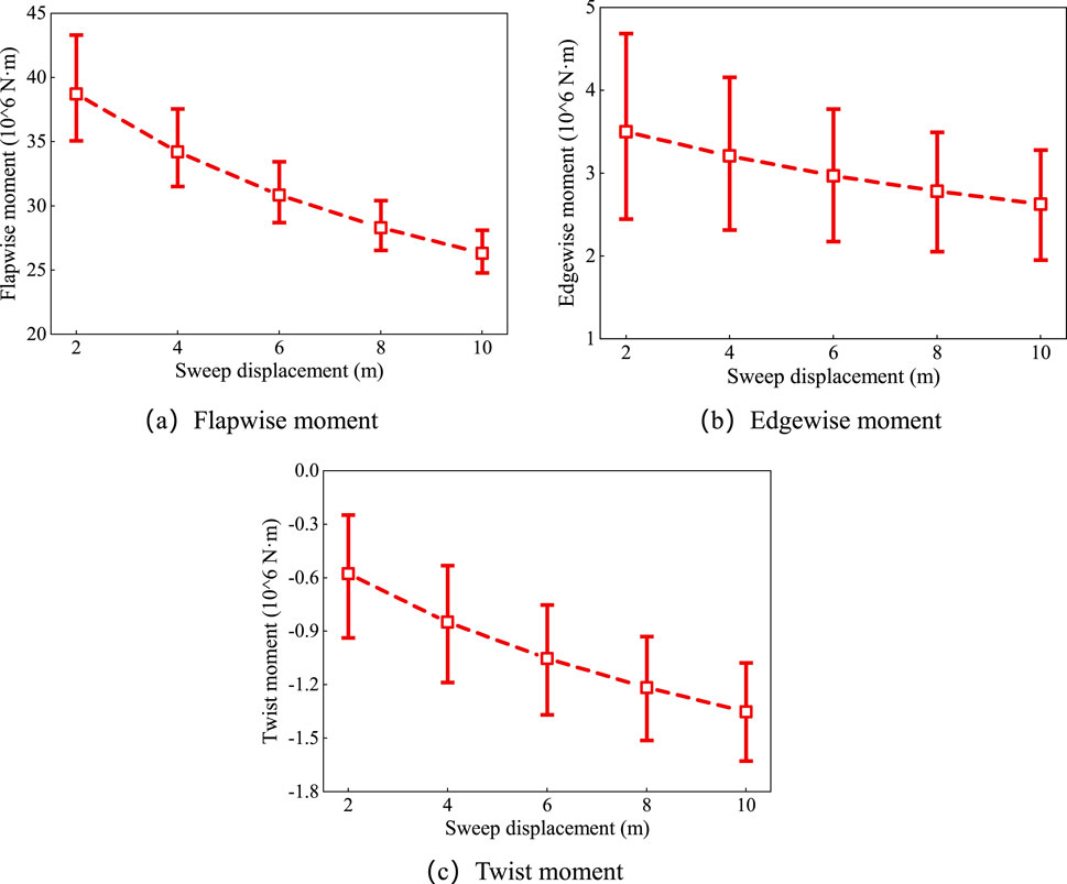
Figure 10. Torque fluctuation amplitude at the root under different sweep displacements. (a) Flapwise moment (b) edgewise moment (c) twist moment.
From the above analysis, it can be seen that the sweep index and sweep start position show similar performance in load reduction, while the sweep displacement has the most significant effect on load reduction. However, large-angle torsional deflections significantly increase the mean torsional moment at the blade root, especially as the sweep displacement increases, the absolute value of the mean torsional moment rises considerably. Additionally, the decrease in the angle of attack caused by torsional deflection inevitably leads to a reduction in wind turbine output power, thus affecting the wind energy utilization efficiency. Therefore, in the design of swept blades, it is necessary to comprehensively consider the range of output power and the impact of bending-torsion coupling characteristics on the torsional moment. Within the allowable range of torsional moments, the sweep displacement can be appropriately increased to effectively reduce the mean and fluctuation amplitude of the flapwise and edgewise moments, thereby optimizing the wind turbine load reduction.
3.4 Aeroelastic characteristics of blade with different sweep displacement
Based on the analysis in the previous section, it is clear that sweep displacement can significantly reduce the mean and fluctuation amplitude of the blade root flapwise moment and edgewise moment loads, thus effectively decreasing blade fatigue damage and structural losses, extending the lifespan of both the blade and the entire system. Therefore, to further analyze the load reduction characteristics of swept blades, this section performs an aeroelastic coupling characteristic analysis of swept blades with different sweep displacements (2 m, 6 m, and 10 m) under a yaw angle of 40°, with a sweep index of 2 and a sweep start position of 0.2 R. From the previous analysis of the overall wind turbine loads, it is evident that as the sweep displacement increases, the mean and fluctuation amplitude of the overall wind turbine load significantly decrease. Additionally, the mean and fluctuation amplitudes of the blade root flapwise moment and edgewise moment also decrease substantially. Although the fluctuation amplitude of the torsional moment gradually decreases, its mean value significantly increases.
To further analyze the blade loads, Figure 11 shows the contour of the blade normal thrust distribution with azimuth angle for the IEA-15 MW wind turbine prototype flexible blade and swept blades with different sweep displacements under yaw conditions. It can be observed that for the straight blade, the thrust distribution on the upper and lower wind turbine planes during one rotation exhibits significant asymmetry, with the thrust mean on the upper half of the wind turbine plane higher than that on the lower half. When the sweep displacement is 2 m, the blade thrust mean significantly decreases, especially on the left half of the wind turbine plane, where the thrust reduces noticeably from 70% to 90% of the blade span. The thrust distribution across the wind turbine plane becomes more uniform compared to the prototype, though some asymmetry still remains. As the sweep displacement increases further to 6 m and 10 m, the blade thrust mean decreases further, and the thrust distribution across the wind turbine plane becomes increasingly uniform, with the asymmetry gradually diminishing. When the sweep displacement reaches 10 m, the blade thrust mean is at its lowest, and the fluctuation amplitude significantly decreases. Therefore, compared to straight blades, swept blades can significantly reduce the mean and fluctuation amplitude of blade thrust, thereby weakening the non-uniformity of the thrust distribution across the wind turbine plane, with these characteristics becoming more pronounced as the sweep displacement increases.
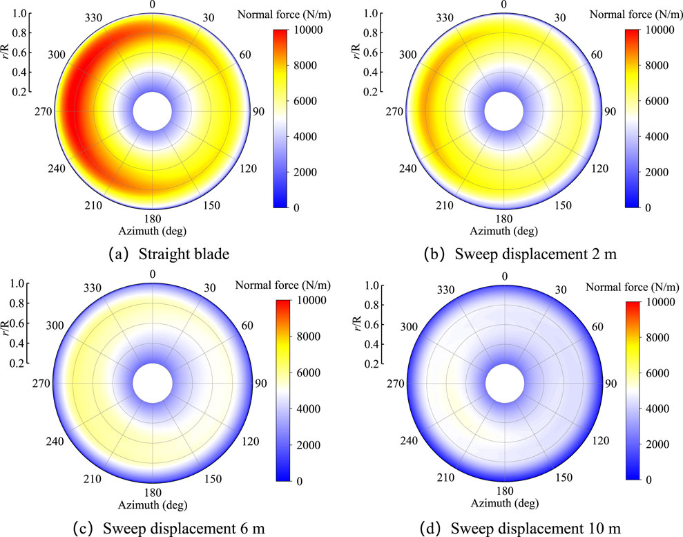
Figure 11. Contour of thrust with azimuth angle for the straight and swept blades under yaw conditions. (a) Straight blade (b) sweep displacement 2 m (c) sweep displacement 6 m (d) sweep displacement 10 m.
The flexible blade undergoes deflection when subjected to aerodynamic loads, resulting in complex aeroelastic phenomena. Figure 12 shows the deflection distribution of a straight blade and swept blades with different sweep displacements (2 m, 6 m, and 10 m) under yaw conditions. From left to right, the figures represent the straight blade and swept blades with sweep displacements of 2 m, 6 m, and 10 m, respectively. From the chart, it can be observed that as the sweep displacement increases, the flapwise deflection generally decreases, with the most significant reduction occurring in the blade tip region (r/R = 0.8–1.0). At a sweep displacement of 10 m, the flapwise deflection reaches its lowest value. This indicates that as the sweep displacement increases, the load on the blade decreases significantly, thereby reducing the flapwise deflection and its fluctuation amplitude. Primarily influenced by gravity, the blade undergoes larger edgewise deflection towards the airfoil’s trailing edge at a 90° azimuth angle, while at a 270° azimuth angle, the edgewise deflection is smaller, directed towards the airfoil’s leading edge. Regarding torsional deflection, increasing the sweep displacement significantly increases the blade’s torsional deflection. When the sweep displacement increases to 6 m and 10 m, the torsional deflection becomes significantly greater than that of the straight blade. However, larger torsional deflection leads to a significant increase in the torsional moment at the blade root.
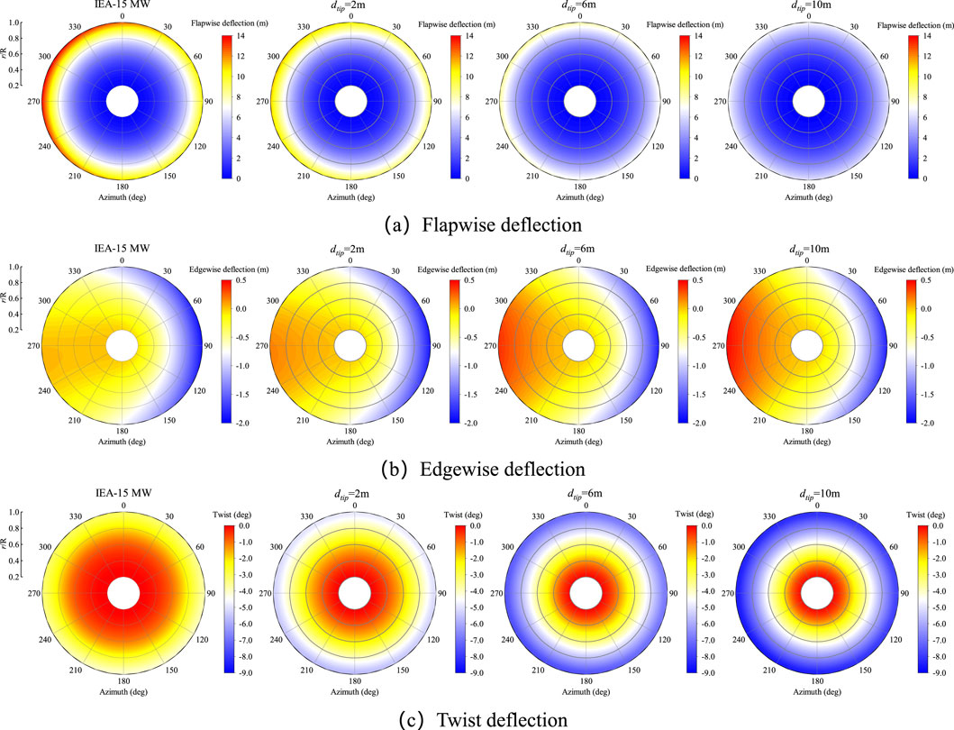
Figure 12. Contour of deflection with azimuth angle for the straight and swept blades under yaw conditions. (a) Flapwise deflection (b) edgewise deflection (c) twist deflection.
The angle of attack of the blade is a key factor determining the aerodynamic load distribution, while the coupling velocity induced by flapwise deflection and the torsional deflection both have significant effects on the angle of attack. Figure 13 shows the spanwise amplitude distribution of the blade’s angle of attack and flapwise velocity under yaw conditions. As shown in Figure 13a, with the increase in sweep displacement, the gradually increasing torsional deflection causes the mean angle of attack to gradually decrease, which effectively reduces the mean blade and wind turbine loads. Additionally, the fluctuation amplitude of the angle of attack also decreases progressively with the increase in sweep displacement. This is because the flapwise velocity, by affecting the axial component of the airfoil section’s velocity triangle, significantly reduces the fluctuation amplitude of the angle of attack. From Figure 13b, it can be observed that as the sweep displacement increases, the mean flapwise velocity at each section of the blade does not change significantly, but the fluctuation amplitude decreases substantially. At the blade tip region, the fluctuation amplitudes of the flapwise velocity for the straight blade and blades with different sweep displacements (2 m, 6 m, and 10 m) are 3.36 m/s, 2.24 m/s, 1.14 m/s, and 0.73 m/s, respectively.
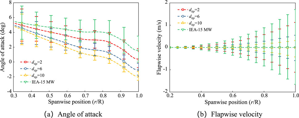
Figure 13. Angle of attack and flapwise velocity spanwise amplitude for the straight and swept blades under yaw conditions. (a) Angle of attack (b) Flapwise velocity.
The shape changes of the swept blade and the load reduction effect influence the wake profile characteristics of the wind turbine, thereby altering the induced effect of the wake on the wind turbine. Figure 14 shows the top view of the wake profile of the wind turbine under yaw conditions for the straight blade and various swept blades. It can be observed that as the sweep displacement increases, the wake distribution gradually becomes more uniform, the spacing between the vortex lines increases, and the disturbance intensity significantly decreases, resulting in a more stable overall wake profile. The wake vortex lines for the straight blade are more closely spaced, and the disturbance intensity is higher. When the sweep displacement increases to 2 m, the spacing between the vortex lines widens, and the wake distribution becomes more uniform, although some disturbances remain. As the sweep displacement increases further to 6 m and 10 m, the wake distribution becomes more uniform and stable, with the overall disturbance significantly reduced and the vortex line spacing noticeably increased. This indicates that a larger sweep displacement in blade design can effectively reduce wake disturbances, making them more stable.
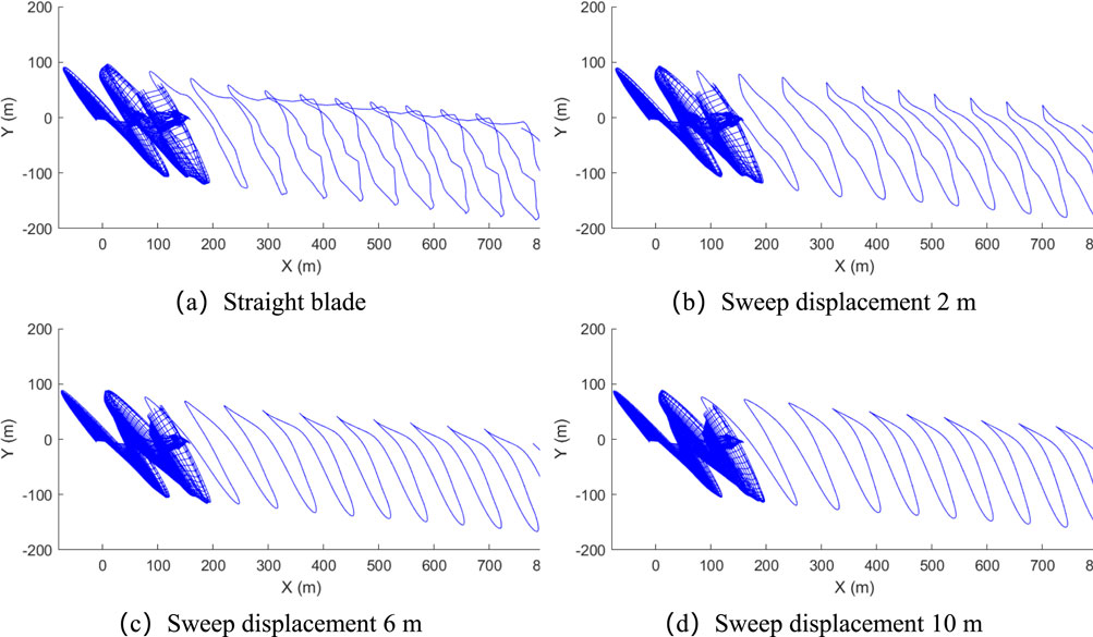
Figure 14. Wake contour of the wind turbine for the straight and swept blades under yaw conditions. (a) Straight blade (b) Sweep displacement 2 m (c) sweep displacement 6 m (d) sweep displacement 10 m.
4 Conclusion
The present study focuses on the IEA-15 MW wind turbine and compares the load characteristics of straight and swept blades under rated operating conditions based on the lifting-line free vortex wake method and geometrically exact beam model. The impact of different sweep parameters on the load characteristics is discussed, and the unsteady aeroelastic coupling characteristics of the wind turbine with swept blades under yaw conditions are analyzed. The following conclusions are obtained:
1) Under rated operating conditions, compared to the straight blade, the swept blade experiences larger torsional deflection in the downward direction due to aerodynamic loads, which reduces the effective angle of attack of the blade, achieving a load reduction effect on both the wind turbine and the blade. Additionally, the fluctuation amplitude of the angle of attack and torsional deflection in the swept blade is smaller, effectively alleviating the fatigue load on the blade.
2) Under yaw conditions, as the sweep index increases from 2 to 4, the mean wind turbine loads and blade root moments show a clear decreasing trend. From 4 to 5, the blade root moment becomes consistent, and the mean wind turbine load starts to increase again. When the sweep start position moves from 0.1 R to 0.3 R, both the wind turbine load and the blade root moment mean values decrease significantly. When the sweep start position moves from 0.3 R to 0.4 R, the fluctuation amplitude of the wind turbine power slightly increases. As the sweep displacement increases from 2 m to 10 m, the wind turbine load decreases significantly, but the mean torsional moment increases substantially. For the blade root moment, the sweep index and sweep start position show similar load reduction effects, while the sweep displacement has the most significant load reduction effect.
3) Under yaw conditions, as the sweep displacement increases: the mean and fluctuation amplitude of the blade thrust significantly decrease, and the thrust distribution across the wind turbine plane gradually becomes more uniform; flapwise deflection shows a decreasing trend, with the most noticeable reduction occurring in the blade tip region; influenced by gravity, the blade experiences large edgewise deflection towards the airfoil’s trailing edge at a 90° azimuth angle, and smaller edgewise deflection towards the airfoil’s leading edge at a 270° azimuth angle; torsional deflection significantly increases, with torsional deflection at sweep displacements of 6 m and 10 m being notably greater than that of the straight blade; the wake distribution becomes more uniform, with vortex line spacing increasing and disturbance intensity decreasing, resulting in a more stable wake profile. Furthermore, as the sweep displacement increases, the progressively increasing torsional deflection and the decreasing fluctuation amplitude of the flapwise velocity lead to a downward trend in both the mean and fluctuation amplitude of the angle of attack.
Data availability statement
The original contributions presented in the study are included in the article/supplementary material, further inquiries can be directed to the corresponding author.
Author contributions
LM: Resources, Writing – review and editing. YL: Software, Writing – original draft, Writing – review and editing. LZ: Methodology, Writing – original draft, Writing – review and editing. HG: Resources, Writing – review and editing. XS: Project administration, Resources, Writing – review and editing. ZD: Supervision, Writing – review and editing.
Funding
The author(s) declare that financial support was received for the research and/or publication of this article. The present study is supported by China Three Gorges Corporation (202303070) and National Key Research and Development Project of China (2023YFB4203100). The funder was not involved in the study design, collection, analysis, interpretation of data, the writing of this article, or the decision to submit it for publication.
Acknowledgments
The authors thank the editor and reviewers for their valuable comments.
Conflict of interest
Authors LM and HG were employed by China Three Gorges Corporation.
The remaining authors declare that the research was conducted in the absence of any commercial or financial relationships that could be construed as a potential conflict of interest.
Generative AI statement
The author(s) declare that no Generative AI was used in the creation of this manuscript.
Publisher’s note
All claims expressed in this article are solely those of the authors and do not necessarily represent those of their affiliated organizations, or those of the publisher, the editors and the reviewers. Any product that may be evaluated in this article, or claim that may be made by its manufacturer, is not guaranteed or endorsed by the publisher.
References
Chen, J., Shen, X., Zhu, X., and Du, Z. (2019a). A study on the capability of backward swept blades to mitigate loads of wind turbines in shear flow. J. Energy Resour. Technol. 141 (8), 081201. doi:10.1115/1.4042716
Chen, J., Shen, X., Zhu, X., and Du, Z. (2019b). Study on composite bend-twist coupled wind turbine blade for passive load mitigation. Compos. Struct. 213, 173–189. doi:10.1016/j.compstruct.2019.01.086
Gaertner, E., Rinker, J., Sethuraman, L., Zahle, F., Anderson, B., Barter, G. E., et al. (2020). IEA wind TCP task 37: definition of the IEA 15-megawatt offshore reference wind turbine. Golden, CO (United States): National Renewable Energy Lab. NREL.
Han, Z., Chen, H., Chen, Y., Su, J., Zhou, D., Zhu, H., et al. (2023). Aerodynamic performance optimization of vertical axis wind turbine with straight blades based on synergic control of pitch and flap. Sustain. Energy Technol. Assessments 57, 103250. doi:10.1016/j.seta.2023.103250
Hodges, D. H. (2009). Geometrically exact, intrinsic theory for dynamics of curved and twisted anisotropic beams. AIAA J. 47 (5), 1308–1309. doi:10.2514/1.40556
Larwood, S., Van Dam, C., and Schow, D. (2014a). Design studies of swept wind turbine blades. Renew. Energy 71, 563–571. doi:10.1016/j.renene.2014.05.050
Larwood, S., Van Dam, C. P., and Schow, D. (2014b). Design studies of swept wind turbine blades. Renew. Energy 71 (11), 563–571. doi:10.1016/j.renene.2014.05.050
McWilliam, M. K., Dicholkar, A. C., Zahle, F., and Kim, T. (2022). Post-optimum sensitivity analysis with automatically tuned numerical gradients applied to swept wind turbine blades. Energies 15 (9), 2998. doi:10.3390/en15092998
Pavese, C., Tibaldi, C., Zahle, F., and Kim, T. (2017). Aeroelastic multidisciplinary design optimization of a swept wind turbine blade. Wind Energy 20 (12), 1941–1953. doi:10.1002/we.2131
Qi, L., Cao, H., Zhang, Y., Zhang, M., Shi, K., and Xu, J. (2022). Data-driven control of the coupled loads for floating wind turbine systems based on deformable trailing edge flaps. Ocean. Eng. 250, 111083. doi:10.1016/j.oceaneng.2022.111083
Sebastian, T., and Lackner, M. A. (2012). Development of a free vortex wake method code for offshore floating wind turbines. Renew. Energy 46, 269–275. doi:10.1016/j.renene.2012.03.033
Shen, X., Chen, J., Hu, P., Zhu, X., and Du, Z. (2018). Study of the unsteady aerodynamics of floating wind turbines. Energy 145, 793–809. doi:10.1016/j.energy.2017.12.100
Shen, X., Zhu, X., and Du, Z. (2021). Load control and unsteady aerodynamics for floating wind turbines. J. power energy 235 (6), 1501–1526. doi:10.1177/0957650921993255
Stäblein, A. R., Hansen, M. H., and Verelst, D. R. (2016). Modal properties and stability of bend-twist coupled wind turbine blades. Wind Energy Sci. Discuss., 1–27.
Thangavelu, S. K., Chow, S. F., Sia, C. C. V., and Chong, K. H. (2021). Aeroelastic performance analysis of horizontal axis wind turbine (HAWT) swept blades. Mater. Today Proc. 47, 4965–4972. doi:10.1016/j.matpr.2021.04.315
Yang, Y., Bashir, M., Michailides, C., Li, C., and Wang, J. (2020). Development and application of an aero-hydro-servo-elastic coupling framework for analysis of floating offshore wind turbines. Renew. Energy 161, 606–625. doi:10.1016/j.renene.2020.07.134
Yang, Y., Fu, J., Shi, Z., Ma, L., Yu, J., Fang, F., et al. (2023a). Performance and fatigue analysis of an integrated floating wind-current energy system considering the aero-hydro-servo-elastic coupling effects. Renew. Energy 216, 119111. doi:10.1016/j.renene.2023.119111
Yang, Y., Shi, Z., Fu, J., Ma, L., Yu, J., Fang, F., et al. (2023b). Effects of tidal turbine number on the performance of a 10 MW-class semi-submersible integrated floating wind-current system. Energy 285, 128789. doi:10.1016/j.energy.2023.128789
Zhang, M., Li, X., Tong, J., and Xu, J. (2020). Load control of floating wind turbine on a Tension-Leg-Platform subject to extreme wind condition. Renew. Energy 151, 993–1007. doi:10.1016/j.renene.2019.11.093
Keywords: aeroelastic performance, yaw condition, free vortex wake method, geometrically exact beam theory, swept blades
Citation: Ma L, Li Y, Zhou L, Guo H, Shen X and Du Z (2025) Load reduction characteristics of swept blade for 15 MW wind turbine. Front. Energy Res. 13:1591837. doi: 10.3389/fenrg.2025.1591837
Received: 11 March 2025; Accepted: 23 April 2025;
Published: 20 May 2025.
Edited by:
Agnimitra Biswas, National Institute of Technology, IndiaReviewed by:
Bofeng Xu, Hohai University, ChinaYang Yang, Ningbo University, China
Nur Alom, National Institute of Technology Meghalaya, India
Copyright © 2025 Ma, Li, Zhou, Guo, Shen and Du. This is an open-access article distributed under the terms of the Creative Commons Attribution License (CC BY). The use, distribution or reproduction in other forums is permitted, provided the original author(s) and the copyright owner(s) are credited and that the original publication in this journal is cited, in accordance with accepted academic practice. No use, distribution or reproduction is permitted which does not comply with these terms.
*Correspondence: Xin Shen, c2hlbnhpbkBzanR1LmVkdS5jbg==