 Qihui Feng1
 Jikai Li
- 1Electric Power Research Institute of Guizhou Power Grid Co. Ltd., Guiyang, China
- 2XJ Electric Co. Ltd., Xuchang, China
In this paper, A coordinated power quality improvement control strategy for three-phase four-Leg flexible interconnection converter (3P4L-FIC) based AC/DC hybrid distribution networks is proposed, which can address three-phase unbalance issues in AC area and double frequency ripple issue in DC area simultaneously without extra components. Firstly, for the problems of three-phase load unbalance in the AC station area, the split-phase power decoupling control based power quality optimization is delivered for 3P4L-FIC based hybrid distribution networks. Secondly, the doubling frequency pulsation mechanism of DC bus voltage during three-phase unbalanced compensation conditions is analyzed in detail, and a DC voltage doubling frequency ripple migration scheme based on hybrid proportional-integral and resonant controller (PI-R) is proposed. Finally, the 3P4L-FIC based low-voltage multi-distribution area simulation model constructed by Matlab/Simulink is verified, and the results show that the three-phase imbalance of the low-voltage AC line is completely compensated, and the double-frequency ripple of the DC bus voltage is greatly reduced, which realizes the synergistic enhancement of the power quality of the AC-DC distribution area.
1 Introduction
With the advancement of the “dual-carbon” goals, distributed renewable energy and electrified loads are rapidly integrated into low-voltage distribution networks, leading to prominent issues such as three-phase imbalance and voltage violations (Xu et al., 2022; Mocci et al., 2025; Tang et al., 2023). The flexible interconnection system for distribution areas employs power electronic conversion devices to establish flexible DC channels between and within distribution areas (Shi et al., 2023; Liu et al., 2023; Sheng et al., 2024). This system enables power quality management in AC distribution areas, dynamic capacity expansion of distribution areas, and efficient/reliable accommodation of large-scale high-penetration distributed generation and high-proportion electrified terminal loads (Xiao et al., 2024; Si et al., 2024; Cai et al., 2023; Zheng et al., 2024; Wang et al., 2008).
Compared with conventional three-leg four-wire flexible interconnection converters, three-phase four-leg (3P4L) converters offer advantages including higher DC voltage utilization, reduced requirements for DC-side input capacitance, and effective control of zero-sequence components. These merits have gradually made them a research hotspot for flexible interconnection converters in distribution areas. Shao and Ma (2008), Lu et al. (2020) implemented individual phase voltage control based on established mathematical models of three-phase four-leg inverters, but their control loops lack complete decoupling, resulting in suboptimal performance. Sun et al. (2020), Zhang et al. (2017), Tan et al. (2019) proposed sequence decomposition strategies combined with feedforward methods to address asymmetric output voltage issues through sequence-decoupled control, though grid harmonics were not considered. Yan et al. (2018), Nguyen and Choi (2018) utilized repetitive controllers to suppress harmonic components and improve grid current quality in three-phase four-leg grid-connected inverters, but their control structures and parameter tuning remain relatively complex.
However, the previous studies effectively address unbalanced loads and harmonic suppression on the AC side but fail to consider that double-frequency instantaneous power fluctuations caused by negative-sequence and zero-sequence components under three-phase AC imbalance conditions propagate to the DC side, inducing double-frequency disturbances. Current solutions for double-frequency power decoupling mainly include passive and active power decoupling methods. Passive power decoupling employs large parallel capacitors (Zeng et al., 2018) or LC resonant circuits (Wang et al., 2024) to absorb double frequency power but suffers from high implementation costs and limited effectiveness. Active power decoupling utilizes switching devices to exchange power with decoupling capacitors for pulsating power compensation (Tao et al., 2023; Huang et al., 2023; Zhang et al., 2023; Luo et al., 2023; Fan et al., 2023; Xu et al., 2020). While enhanced switching configurations improve secondary ripple suppression, they simultaneously escalate system power losses. Tan et al. (2025) proposes a control strategy for three-phase four-leg PWM rectifier under unbalanced grid voltage conditions, which aims at achieving not only no second harmonic in dc output voltage, but also unity power factor operation for each phase. Zhou and Lu (2025), Bhowmick et al. (2025) used an active power decoupling (APD) or boost converter circuit to suppression the double-frequency disturbances in DC bus, while the additional APD circuit will increase the system cost.
To address these limitations, this paper proposes a coordinated AC-DC distribution area power quality optimization strategy based on split-phase power decoupling and resonant control, comprehensively considering three-phase imbalance, voltage violations in AC distribution areas, and double-frequency ripple issues in DC distribution areas. The strategy is implemented within the three-phase four-leg flexible interconnected converter (3P4L-FIC) based distribution area architecture shown in Figure 1. Specifically, a power decoupling control strategy based on positive-negative-zero sequence separation is introduced at the inverter side (VSC2) to address the three-phase load unbalance issues. Simultaneously, a resonant-based double-frequency current suppression strategy is implemented at the flexible interconnection rectifier (VSC1) side to mitigate double-frequency voltage ripples in DC distribution areas. The proposed strategy can address three-phase unbalance issues in AC area and double frequency ripple issue in DC area simultaneously without extra components.
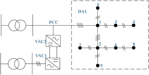
Figure 1. Diagram of 3P4L-FIC based AC/DC hybrid distribution networks.
The rest of this study is structured thus. Section 2 presents the mathematical model of 3P4L Converters. Section 3 presents a mechanism of double-frequency DC voltage ripples under unbalanced operating conditions. Section 4 proposes a coordinated power quality improvement strategy for AC-DC distribution areas. Section 5 gives simulation validation and analysis, and Section 6 summarizes the key conclusions drawn from our study.
2 Mathematical model of three-phase four-leg converters
Conventional three-phase three-leg converters exhibit interphase coupling in output power, thereby lacking the capability for independent three-phase power regulation. In contrast, the 3P4L-FIC introduces a zero-sequence leg to the traditional three-leg topology (as illustrated in Figure 2), enabling each port to generate independent voltages, which structural enhancement facilitates decoupled control of unbalanced three-phase power.
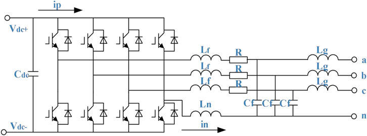
Figure 2. Topology architecture of three-phase four-leg converter.
Using the current through the filter inductor Lf of the three-phase four-leg inverter
Where
From Equations 1–3, it is evident that if the neutral inductor and its equivalent resistance are neglected, the three-phase four-leg inverter system reduces to three independent single-phase full-bridge inverter systems. When the neutral inductor is considered, however, mutual coupling arises between the bridge legs, preventing the system from being treated as three decoupled inverter units. This observation underscores the inherent difficulty in achieving decoupled control of the three-phase four-leg inverter in the three-phase stationary coordinate frame.
Translating the fundamental sinusoidal components from the three-phase stationary coordinate frame into a two-phase stationary coordinate frame, followed by Laplace transformation, yields the system’s frequency-domain control model, expressed as
It can be seem from the Equations 4–6 that under small-signal perturbations around the quiescent operating point, since the DC voltage
From Equations 7–9, it can be observed that the mathematical model of the three-phase four-leg converter is mutually decoupled in the
3 Mechanism of DC double frequency voltage ripple under unbalanced operating conditions
The three-phase four-leg inverter is directly connected to the low-voltage distribution network via an LCL filter. In the three-phase four-wire system, due to the inclusion of zero-sequence voltage and current components, the system’s instantaneous real power
It can be seem from Equation 10 that the zero-sequence instantaneous power in the system is independent of the positive- and negative-sequence instantaneous powers. According to (Dong et al., 2020; Gao et al., 2016), the instantaneous complex power output from the converter’s AC side can be expressed as (excluding the zero-sequence component).
In Equation 11,
The zero-sequence voltage and current components are defined as
In the Equation 12,
In the equations,
By integrating the above analysis, the total instantaneous power of the three-phase four-wire system is expressed as
From Equation 14, under unbalanced operating conditions, the instantaneous power fluctuations at the second harmonic frequency generated by the negative-sequence and zero-sequence components will penetrate into the DC side, causing second harmonic frequency disturbances in the DC network. This seriously affects the reliability and stability of the system.
4 Coordinated power quality improvement strategy for 3P4L-FIC based AC-DC distribution areas
Figure 3 shows the overall block diagram of the proposed coordinated power quality improved control strategy for 3P4L-FIC distribution areas, which consists of two part. One is the split phase power decoupling control strategy for three phase unbalance compensation of the AC distribution network, which is based on the positive, negative, and zero sequence separation control on the inverter side (VSC2) of the 3P4L-FIC. The other one is hybrid proportional-integral and resonant controller (PI-R) based double-frequency voltage ripple suppression strategy for DC-bus, which is implemented on the rectifier side (VSC1) of the 3P4L-FIC. The proposed coordinated strategy can address three-phase unbalance issues in AC area and double frequency ripple issue in DC area simultaneously without extra components.
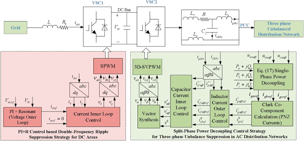
Figure 3. Overall diagram of the proposed coordinated power quality improvement strategy for 3P4L-FIC based AC-DC distribution areas.
4.1 Split-phase power decoupling control based three-phase unbalance compensation strategy for AC distribution areas
Based on the mathematical model of the 3P4L-FIC established in Section 2 under the
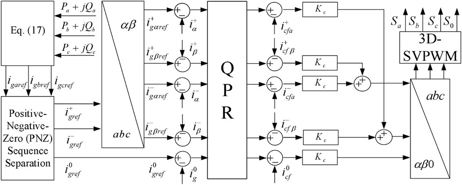
Figure 4. The overall control block diagram of the proposed split-phase power decoupling strategy in VSC2.
In the diagram, Kr is the proportional coefficient, and QPR denotes the Quasi-Proportional Resonant (QPR) controller, whose transfer function is expressed as:
In Equation 15,
Based on the generalized instantaneous reactive power theory for single-phase systems (Akagi et al., 2007), the αβ two-phase signals are constructed to obtain the single-phase instantaneous active power and reactive power.
In Equation 16
Due to the advantages of the Second-Order Generalized Integrator (SOGI), such as harmonic filtering, the SOGI (Wei et al., 2016) is adopted to construct the αβ-axis signals for
4.2 PI-R control based double-frequency ripple suppression strategy for DC areas
The emergence of double-line-frequency voltage ripple components on the DC side, combined with the insufficient gain of conventional rectifier control loops at double-line-frequency, results in the inability of standard rectifier control systems to maintain stable DC voltage output under unbalanced load conditions. According to the Internal Model Principle, to achieve zero steady-state error tracking of the double-line-frequency pulsating components in the output voltage caused by load imbalance, the controller must incorporate sinusoidal internal models at the corresponding frequencies. This ensures that the open-loop magnitude-frequency characteristic curve of the system exhibits infinite gain at double-line-frequency (Zou et al., 2014; Ortega et al., 2021).
To address the double-line-frequency disturbances in the DC bus caused by three-phase imbalance in the AC distribution area, this paper employs a damped resonant controller to suppress the double-line-frequency pulsating components within the control loop. A voltage outer loop PI-R control strategy is proposed, with its expression given in Equation 17. The overall control block diagram of the VSC1 ripple suppression strategy is illustrated in Figure 5.
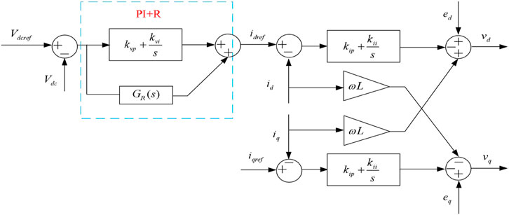
Figure 5. The overall control block diagram of PI-R control based double-frequency ripple suppression strategy in VSC1.
In Equation 18,
Figure 6 shows the comparison of voltage loop frequency response characteristics between the conventional voltage outer loop and the inverter with the introduced resonant controller. The parameters of the PI-R controller are set as follows: proportional coefficient
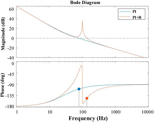
Figure 6. Comparison bode diagram between PI and PI-R outer loop.
5 Simulation verification and analysis
A simulation model of the dual-terminal low-voltage flexible interconnected grid, as shown in Figure 1, was developed on the MATLAB platform. The converter system parameters and control parameters are summarized in Tables 1, 2. Based on measurement data from a demonstration construction project in a city in Guizhou Province, this study analyzes whether the distribution area experiences operational issues such as three-phase imbalance and voltage deviation under typical conditions, with the power factor set to 0.9. The operational data for Distribution Area I are as follows:
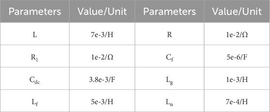
Table 1. System parameters.
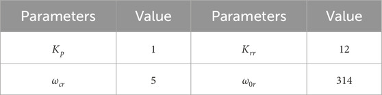
Table 2. Control parameters.
Scenario 1: Data from 12:00 noon are selected as a typical case of high photovoltaic (PV) penetration and low load proportion, three phase load and photovoltaic access data for substation area I are summarized in Table 3.
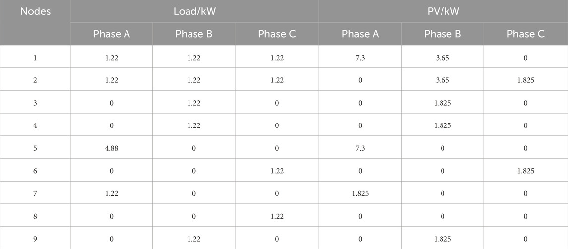
Table 3. Three phase load and photovoltaic access data for distributor area I (Scenario 1).
Scenario 2: Data from 18:00 (6:00 p.m.) are selected as a typical case of high load proportion and low PV penetration. The three phase load and photovoltaic access data for substation area I are summarized in Table 4.
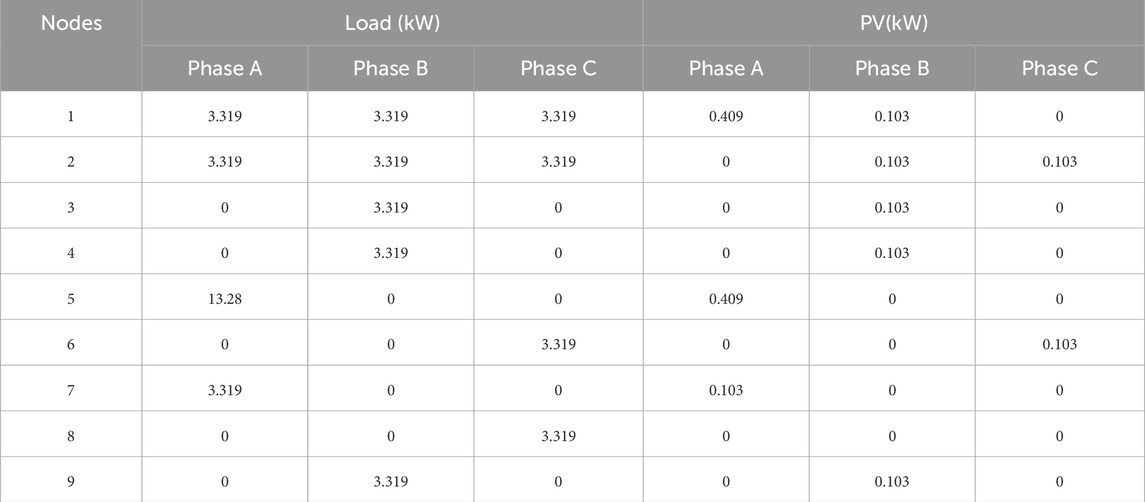
Table 4. Three phase load and photovoltaic access data for distribution area I (Scenario 2).
5.1 Verification of power quality optimization strategy for AC distribution areas
Scenario 1: Figures 7a–c illustrate the PCC voltage waveforms, source-side output current waveforms, and three-phase unbalance rates before and after implementing the proposed three-phase unbalance compensation control strategy. When the compensation strategy is blocked, the distribution area operated independently, with Distribution Area I bearing the full three-phase unbalanced load. The three-phase unbalance rate of its output currents entirely depended on the load level, resulting in a PCC voltage unbalance rate of approximately 3% and a source-side output current unbalance rate as high as 47%, exceeding the 2% three-phase unbalance limit. This severely compromised the stable operation of the distribution area. After enable the compensation strategy, the PCC voltage unbalance rate was reduced to nearly 0%, and the source-side current unbalance rate decreased to around 1.7%, significantly mitigating the three-phase imbalance and complying with the system’s unbalance limit requirements.
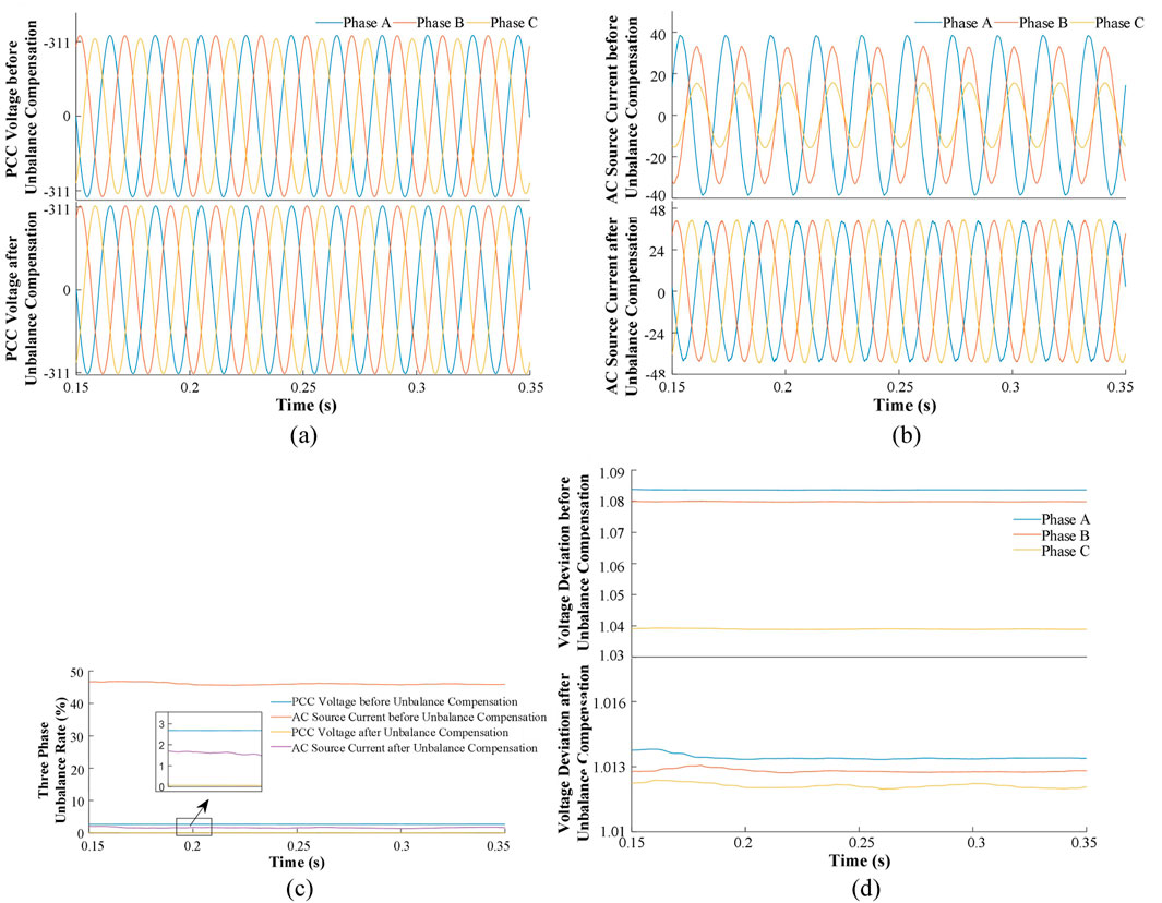
Figure 7. Comparison waveform under scenario 1 before and after the unbalance compensation. (a) PCC Voltage Waveform. (b) Grid AC Source Output Current Waveform. (c) Three-Phase Unbalance Rate. (d) Voltage Deviation.
Figure 7d shows the voltage deviation value before and after unbalance compensation. During the high PV penetration and low load proportion period (midday), the PV generation exceeded the load demand, causing reverse power flow and overvoltage at the PCC. As shown in Figure 7d, the voltage deviations without compensation for Phases A, B, and C were 1.084 pu, 1.08 pu, and 1.039 pu, respectively. The deviations for Phases A and B exceeded the upper limit of 1.07 pu, risking insulation damage to equipment. When the compensation strategy is enabled, Distribution Area I transferred a portion of PV generation to Distribution Area II, reducing its voltage deviation. The PCC phase voltage deviations stabilized around 1.013 pu, closer to the nominal value of 1 pu, thereby enhancing equipment safety.
Figure 8 shows the current waveforms at the source-side, load-side, and inverter-side under the compensation conditions. As demonstrated in Figure 8, after implementing the compensation control strategy, the inverter-side output current compensates for the unbalanced load-side output current, thereby reducing the three-phase unbalance rate of the source-side output current and mitigating its adverse impact on system stability.
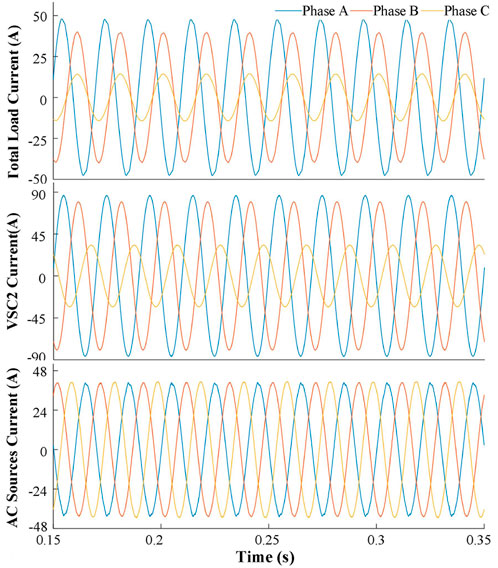
Figure 8. The current waveform on the load, AC sources and VSC2 sides under the compensation conditions.
Scenario 2: Figures 9a–c illustrate the PCC voltage waveforms, source-side output current waveforms, and three-phase unbalance rates before and after implementing the proposed three-phase unbalance compensation control strategy. As shown in Figures 9a–c, under Scenario two operating conditions, the PCC voltage unbalance rate is approximately 3.1%, and the source-side output current unbalance rate reaches 27%, both exceeding the three-phase unbalance limit. After enable the compensation strategy, the PCC voltage unbalance rate is reduced to around 0.1%, and the source-side current unbalance rate decreases to 0.9%, effectively mitigating the three-phase imbalance and meeting the system’s unbalance limit requirements. Figure 9d shows the voltage deviation waveforms before and after the unbalance compensation. During the low PV penetration and high load proportion period (evening), reduced PV generation combined with increased load demand leads to under voltage at the PCC. As seen in Figure 9d, the voltage deviations without compensation for Phases A, B, and C are 0.92 pu, 0.956 pu, and 0.974 pu, respectively. The deviations for Phases A and B fall below the lower voltage deviation limit (0.97 pu). When the compensation strategy is enabled, the PCC phase voltage deviations stabilize near 1 pu, ensuring safer operation of the distribution area. Figure 10 shows the current waveforms on the source side, the load side, and the inverter side under the compensation conditions. It can be seen that, after implementing the compensation control strategy, the output current on the inverter side compensates for the unbalanced output current on the load side, achieving three-phase balance on the source side.
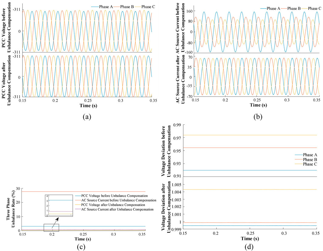
Figure 9. Comparison waveform under scenario 1 before and after the unbalance compensation. (a) PCC Voltage Waveform. (b) Grid-Side Output Current Waveform. (c)Three-Phase Unbalance Rate. (d) Voltage Deviation.
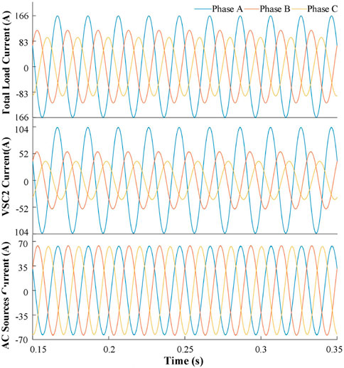
Figure 10. The current waveform on the load, AC sources and VSC2 sides under the compensation conditions.
5.2 Verification of the double-frequency ripple suppression strategy
Figure 11a, b show the double-line-frequency waveforms of the DC bus voltage under Scenarios one and 2, respectively, comparing traditional PI control with the PI-R control. As shown in Figures 11, 12, the conventional PI voltage outer loop fails to suppress the double-line-frequency pulsating components in the DC voltage. In contrast, the PI-R control effectively mitigates the double-frequency components by introducing a resonant controller into the traditional control loop, while maintaining excellent steady-state characteristics.
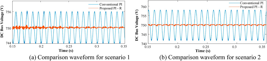
Figure 11. Comparison of PI and PI-R control voltage waveform under different scenarios. (a) Comparison waveform for scenario 1. (b) Comparison waveform for scenario 2.
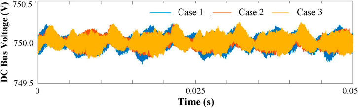
Figure 12. Suppression performance comparison of DC bus voltage ripple under different inductance parameters.
To validate the proposed strategy sensitive to the change of the inductance value,the suppression performance of DC bus voltage ripple under different inductance parameters are carried out. The results are plotted in Figure 12, in which three cases are set. All the inductance values both in inverter and rectifier side in Case 1 are reduced by 50%, and increase 50% in Case 3, and Case 2 keep the same value as Table 1. It can be seem that under different inductance variations, the double-frequency peak-to-peak ripple in dc bus voltage can be suppressed by the proposed method within the range of ±1 V, which fully demonstrates that the proposed strategy sensitive to the change of the inductance value.
Table 5 summarizes the performance comparison between the proposed control strategy and the traditional method under two scenarios. The results show that the proposed split-phase power decoupling method can reduce the power unbalance degree at the AC sources to less than 2%, which can ensure the safe and balanced operation of the AC transformer. Moreover, the proposed method can compensate for the voltage unbalance degree at the PCC point and simultaneously solve the voltage deviation problem. The proposed double-frequency ripple suppression method can effectively suppress the second - harmonic voltage, reducing the peak-peak DC voltage ripple pulsation to around 1–2 V at the minimum. The results fully demonstrate the effectiveness of the proposed control strategy.

Table 5. The performance comparison for conventional and proposed strategy.
6 Conclusion
This paper proposes a coordinated power quality improvement strategy for 3P4L-FCI based AC-DC distribution areas. To address issues such as three-phase imbalance and voltage limit violations in AC distribution areas, a split-phase power decoupling control strategy utilizing the three-phase four-leg converter is developed, effectively reducing the PCC voltage unbalance rate, source-side output current unbalance rate, and voltage deviations under two extreme operating conditions. Furthermore, by analyzing the double-line-frequency pulsation mechanism of the DC bus voltage under unbalanced AC distribution conditions, a double-frequency ripple suppression scheme based on a hybrid proportional-integral and resonant controller (PI-R) controller is proposed, which significantly mitigates the double-frequency components in the DC bus voltage. Finally, a MATLAB/Simulink-based simulation model of 3P4L-FCI based AC-DC distribution areas is established. The results validate the effectiveness of the proposed control strategies.
Data availability statement
The original contributions presented in the study are included in the article/supplementary material, further inquiries can be directed to the corresponding author.
Author contributions
QF: Conceptualization, Writing – original draft. JL: Conceptualization, Writing – review and editing. JZ: Conceptualization, Methodology, Writing – review and editing. YX: Funding acquisition, Supervision, Writing – review and editing. QH: Data curation, Investigation, Writing – review and editing. YG: Investigation, Validation, Writing – review and editing.
Funding
The author(s) declare that financial support was received for the research and/or publication of this article. This work was supported by Key Science and Technology Projects of China Southern Power Grid Corporation (GZKJXM20220041), and part by National Key Research and Development Program of China (2022YFE0205300).
Conflict of interest
Authors QF, JZ, YX, and YG were employed by Electric Power Research Institute of Guizhou Power Grid Co. Ltd. Authors JL and QH were employed by XJ Electric Co. Ltd.
The authors declare that this study received funding from China Southern Power Grid Corporation. The funder had the following involvement in the study: providing financial support for the construction of the simulation environment and data assistance, participated in manuscript revision and writing.
Generative AI statement
The authors declare that no Generative AI was used in the creation of this manuscript.
Publisher’s note
All claims expressed in this article are solely those of the authors and do not necessarily represent those of their affiliated organizations, or those of the publisher, the editors and the reviewers. Any product that may be evaluated in this article, or claim that may be made by its manufacturer, is not guaranteed or endorsed by the publisher.
References
Akagi, H., Watanabe, E. H., and Aredes, M. (2007). Instantaneous power theory and applications to power conditioning. Wiley-IEEE Press, 1–369. doi:10.1002/9781119307181
Bhowmick, S., Mukherjee, D., Basu, T. S., and Chakraborty, C. (2025). A three-phase four-leg neutral-point-clamped photovoltaic inverter with decoupled active and reactive power control and DC-link voltage ripple minimization under unbalanced grid operation. IEEE Trans. Power Electron. 40 (6), 7829–7843. doi:10.1109/tpel.2025.3538166
Cai, H., Guo, Q., Yang, R., et al. (2023). Dual-end grid-forming control of flexible DC transmission system for weak grid interconnection. Electr. Power Autom. Equip. 43 (09), 202–209. doi:10.16081/j.epae.202308014
Dong, H., Yuan, S., and Li, C. (2020). Power pulsation suppression of multi-source microgrid based on improved P/Q control. J. Shenyang Univ. Technol. 42 (01), 7–11. doi:10.79783/j.cnki.pspc.2217302
Fan, E., Zhao, L., and Li, Y. (2023). Second harmonic suppression and design of control parameters for a dual-active-bridge series resonant converter applied to a two-stage inverter. Power Syst. Prot. Control 51 (17), 58–68. doi:10.19783/j.cnki.pspc.221735
Gao, Y., Zhao, W., and Huang, S. (2016). Reactive power definitions in single-phase circuits based on instantaneous reactive power theory. Electr. Meas. and Instrum. 53 (20), 1–8. doi:10.3969/j.issn.1001-1390.2016.20.001
Huang, H., Chen, X., and Qu, Y. (2023). Distributed AC/DC converter and its active power decoupling control. Power Electron. 57 (10), 130–132+140. doi:10.3969/j.issn.1000-100X.2023.10.034
Liu, D., Liu, Z., Wang, T., Xie, Z., He, T., Dai, A., et al. (2023). A novel refined regulation method with modified genetic commutation algorithm to reduce three-phase imbalanced ratio in low-voltage distribution networks. Energies 16, 7838. doi:10.3390/en16237838
Lu, X., Sun, F., and Ma, W. (2020). Research on control strategy of three-phase four-leg inverter. Electr. Meas. and Instrum. 57 (12), 32–37. doi:10.19753/j.issn1001-1390.2020.12.006
Luo, X., Bian, D., and Zhao, X. (2023). Active power decoupling control strategy of single-phase inverter based on buck converter. Water Resour. Power 41 (06), 206–210. doi:10.20040/j.cnki.1000-7709.2023.20221534
Mocci, S., Ruggeri, S., and Pilo, F. (2025). Low-voltage renewable energy communities’ impact on the distribution networks. Energies 18, 126. doi:10.3390/en18010126
Nguyen, M.-K., and Choi, Y.-O. (2018). PWM control scheme for quasi-switched-boost inverter to improve modulation index. IEEE Trans. Power Electron. 33 (05), 4037–4044. doi:10.1109/tpel.2017.2717487
Ortega, R., García, V. H., García-García, A. L., Rodriguez, J. J., Vásquez, V., and Sosa-Savedra, J. C. (2021). Modeling and application of controllers for a photovoltaic inverter for operation in a microgrid. Sustainability 13, 5115. doi:10.3390/su13095115
Shao, Y., and Ma, H. A. (2008). Triangle wave injection control strategy for three-phase four-leg inverter. Electr. Meas. and Instrum. (01), 48–51+60. doi:10.3969/j.issn.1001-1390.2014.19.015
Sheng, W., Liu, K., and Li, Z. (2024). Review of basic theory and methods of morphological evolution and safe and efficient operation of new distribution system. High. Volt. Eng. 50 (01), 1–18. doi:10.13336/j.1003-6520.hve.20232145
Shi, F., Ma, Y., and Xu, D. (2023). Improved stability control method of LCL-type grid-connected inverter under weak grid. Renew. Energy Resour. 41 (12), 1700–1704. doi:10.13941/j.cnki.21-1469/tk.2023.12.014
Si, J., Wu, X., Guo, Q., Hui, C., Liang, C., Junhui, H., et al. (2024). Review of flexible interconnection of regional grids interconnection planning and operation techniques for high percentage of renewable energy consumption. Power Syst. Technol., 1–18. doi:10.13335/j.1000-3673.pst.2023.2116
Sun, Y., Chen, Y., and Shi, K. (2020). “Improved sequential control strategy for three-phase four-leg inverter.” in Proceedings of the CSU-EPSA Shanghai, China. 32 (02), 105–112. doi:10.19635/j.cnki.csu-epsa.000183
Tan, C., Xing, Y., Chen, Q., and Liyan, Z. (2019). Anti-windup strategy of repetitive controller for three-phase four-leg grid-tied inverter. Trans. China Electrotech. Soc. 34 (17), 3631–3639. doi:10.19595/j.cnki.1000-6753.tces.180581
Tan, G., Guo, X., Zhao, W., Qi, L., and Sun, X. (2025). Second harmonic suppression for DC output voltage of three-phase four-leg PWM rectifier under unbalanced grid voltage conditions. IEEE Trans. Power Electron., 1–17. doi:10.1109/tpel.2025.3551801
Tang, W., Zhang, Q., and Zhang, L. (2023). Concept, key technologies and development direction of multilevel AC/DC interconnection in new distribution system. Automation Electr. Power Syst. 47 (06), 2–17. doi:10.7500/AEPS20221031014
Tao, H., Yang, N., and Wang, H. (2023). Ripple analysis and control of MAPD cascaded H-bridge rectifier under capacitor mismatch. Electr. Mach. Control 27 (12), 145–158. doi:10.15938/j.emc.2023.12.015
Wang, L., Zang, S., and Li, C. (2024). A single-phase current-source converter based on the symmetrical half-bridge power decoupling topology. Transactions of China Electrotechnical Society 39 (24), 1–13. doi:10.19595/j.cnki.1000-6753.tces.231924
Wang, Z., Lin, J., and Chen, H. (2008). Control of distributed power inverter with unbalanced and nonlinear loads. Automation Electr. Power Syst. (01), 48–51+60. doi:10.3321/j.issn:1000-1026.2008.01.011
Wei, Z., Ru, X., and Shi, W. (2016). Control strategy for microgrid inverter under unbalanced load conditions. Automation Electr. Power Syst. 40 (20), 76–82. doi:10.7500/AEPS20151028004
Xiao, Q., Xu, J., and Jia, H. (2024). Analysis of the influence of overmodulation conditions on the operational stability of the hybrid modular multilevel. J. Tianjin Univ. Sci. Technol. 57 (02), 123–136. doi:10.11784/tdxbz202211030
Xu, Y., Liu, H., Xiong, X., Yu, J., Yao, S., Hai, Z., et al. (2022). Key technologies and development modes of flexible interconnection of low-voltage distribution station area. Proceedings of the CSEE 42 (11), 3986–4001. doi:10.13334/j.0258-8013.pcsee.210578
Xu, Y., Zhang, M., and Yang, Y. (2020). Dual quasi-proportional complex integral control strategy of the four-leg inverter with unbalanced load. Power Syst. Prot. Control 48 (07), 141–150. doi:10.19783/j.cnki.pspc.190490
Yan, F., Huang, L., and Wang, H. (2018). Composite control method for three-phase four-leg inverter. J. Hebei Univ. Nat. Sci. Ed. 38 (01), 105–112. doi:10.3969/j.issn.1000-1565.2018.01.016
Zeng, H., Xu, J., and Chen, D. (2018). Single-stage charging/discharging high-frequency link DC-AC converter with low-frequency harmonic suppression. Trans. China Electrotech. Soc. 33 (08), 1783–1792. doi:10.19595/j.cnki.1000-6753.tces.161912
Zhang, H., Cai, X., and Yang, X. (2017). Sequence decomposition control strategy for virtual synchronous generator based on three-phase four-leg inverter. Power Syst. Technol. 41 (04), 1291–1299. doi:10.13335/j.1000-3673.pst.2016.1790
Zhang, Y., Fu, W., and Liu, P. (2023). Research on four-switch power decoupling circuit based on AC-side of an inverter. Electr. Mach. Control 27 (08), 142–153. doi:10.15938/j.emc.2023.08.015
Zheng, G., Zhu, E., and Zhang, H. (2024). Flexible interconnection planning for distribution station areas of high-ratio photovoltaic based on master-slave game. Electr. Power Constr. 45 (04), 100–110. doi:10.12204/j.issn.1000-7229.2024.04.010
Zhou, J., and Lu, Z. (2025). Two-terminal three-phase unbalance management strategy for flexible interconnections taking into account DC doubling suppression. Electric power automation equipment. doi:10.16081/j.epae.202502008
Keywords: power quality improvement, three-phase four-bridge-arm converter, unbalance compensation, double-frequency ripple, flexible interconnection
Citation: Feng Q, Li J, Zhou J, Xu Y, He Q and Gao Y (2025) A coordinated power quality improvement control strategy for AC/DC hybrid distribution networks based on three-phase four-leg flexible interconnection converter. Front. Energy Res. 13:1602269. doi: 10.3389/fenrg.2025.1602269
Received: 29 March 2025; Accepted: 28 April 2025;
Published: 19 May 2025.
Edited by:
Wenping Zhang, Tianjin University, ChinaCopyright © 2025 Feng, Li, Zhou, Xu, He and Gao. This is an open-access article distributed under the terms of the Creative Commons Attribution License (CC BY). The use, distribution or reproduction in other forums is permitted, provided the original author(s) and the copyright owner(s) are credited and that the original publication in this journal is cited, in accordance with accepted academic practice. No use, distribution or reproduction is permitted which does not comply with these terms.
*Correspondence: Jikai Li, bGlqaWthaUB4ai5jZWUtZ3JvdXAuY24=