 Jiahua Ni1
 Yinxiao Zhu
- 1PowerChina Huadong Engineering Cooperation Limited, Hangzhou, China
- 2College of Electrical Engineering, Zhejiang University, Hangzhou, China
Differential power processing (DPP) architectures are effective solutions for photovoltaic (PV) systems experiencing uncertainties in environmental conditions, such as non-uniform irradiation, which can significantly degrade electricity production efficiency and operating safety. Among the different architectures available, the PV-to-bus DPP configuration has shown excellent performances for control flexibility and galvanic isolation capability. However, recent control schemes for PV-to-bus architectures offer lower-than-desirable efficiency enhancements, such as those involving implementation complexities and unit power distributions. Hence, a unit power rating balancing (UPRB) scheme is proposed in this work to reconfigure the distribution of differential power among the unit converters with the aim of ensuring submodule-level optimization and enhanced performance of the entire PV system. The proposed UPRB scheme integrates perturbation-and-observation-based maximum power-point tracking units to maximize the energy harvested from PV modules, and the unit balance-point tracking unit is employed to determine the optimal string current reference directly for mitigating the unbalanced differential power in the DPP units. By suppressing the maximum processed power in each DPP unit, the capital cost and system size can be reduced. Simulation and experimental studies were conducted, whose evaluation results support the applicability of the proposed control scheme.
1 Introduction
Recently, solar power generation programs have gained widespread acceptance globally given the advancements in photovoltaic (PV) technology (Blaabjerg et al., 2023). In typical solar farms and distributed PV systems, the PV panels are first connected in series to enhance the voltage for achieving the required value and then connected in parallel for construction of the PV generation grid (Zhu et al., 2024b). However, the uncertainties associated with environmental conditions, such as partial shading, dust deposition, and cell aging, can easily cause series string mismatches between the panels and reduce the total power generated by the distributed PV system (Aifan et al., 2024; Zhu et al., 2024a). Typically, bypass diodes are used to protect a PV substring with 20–24 cells. However, the power generated still exhibits a significant reduction trend under various mismatch conditions owing to the occurrence of multiple maximum power points (MPPs) on the power–voltage curve (Nunes et al., 2022; Ali et al., 2023; Zhu et al., 2022). To mitigate the power losses caused by multiple MPP scenarios, various advanced maximum power-point tracking (MPPT) solutions have been proposed for partially shaded PV systems, such as the reference-voltage-line-aided method (Li et al., 2022), particle swarm optimization algorithm (Refaat et al., 2023), peafowl optimization algorithm (Li et al., 2021), and machine-learning-based method (Yılmaz et al., 2023). However, these methods have mostly increased the implementation complexity and computational requirements of the control units. Furthermore, a portion of the available power from the PV string is dissipated by implementing such MPPT methods, which reduces the overall energy efficiency of the system (Chu et al., 2024).
To address these issues, new architectures like full power processing (FPP) and differential power processing (DPP) have been proposed to enhance power generation under PV mismatch conditions. As shown in Figure 1, DC power optimizers (DCPOs) and microinverters are the widely adopted power interfaces in the FPP architecture for distributed PV systems (Celik et al., 2018; Ramli and Salam, 2019). Here, each DCPO or microinverter is connected in series and includes an MPPT unit to maximize the power extracted from the corresponding PV module, thereby guaranteeing the efficiency of the system. However, a certain level of power loss is unavoidable in this architecture as the PV power production is fully processed, degrading both the energy production and system reliability (Shenoy et al., 2013). Compared to FPP, the DPP architecture reduces power losses by processing only a portion of the total PV power through the DPP converter units while the main power is fed to the centralized converter directly (Jeong et al., 2019). This means that only a fraction of the total power is processed by the DPP converter and that the power rating specified for each DPP converter is relatively low; further, this architecture requires a small-sized and low-cost design (Amaral da Luz et al., 2023). Notably, under consideration of similar converter efficiencies, the total power loss of the DPP architecture is lower than that of the DCPO on average. Meanwhile, if a low-level or no-mismatch condition occurs, none of the power passes through the DPP converter, which further improves the power transmission efficiency. A comparison between FPP and DPP showed that the system could achieve higher efficiency under the DPP architecture owing to contribution from the fraction of output power processing capability (Olalla et al., 2015).
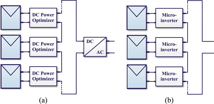
Figure 1. Typical full power processing architectures for distributed photovoltaic (PV) systems: (a) DC power optimizer; (b) microinverter.
The DPP architecture can be broadly divided into two types, namely PV element to PV element (PV-PV) architecture and PV element to bus architectures, according to the port connection conditions of the DPP converter. For the PV-PV architecture shown in Figure 2a, the number of DPP converter units is always one less than the number of PV modules; here, the proposed topologies include switched-capacitor converter (SCC) (Uno et al., 2022) and switched-inductor converter (SLC) (Shenoy et al., 2013). The SCC system is based on the principle of voltage equalization among all submodules but cannot achieve an accurate MPP for each submodule when a mismatch occurs (Dong et al., 2019). The synchronous bidirectional buck-boost topology is used as the DPP converter in the SLC configuration, which provides bidirectional transition of power flow between the relative submodules. However, the PV-PV architecture requires connections between adjacent PV elements, which increases the system complexity and necessitates coordinated control. The PV element to bus DPP architecture topologies can be divided into PV element to isolated port (PV-IP) and PV element to non-isolated port (PV-NIP) bus architectures, as demonstrated in Figures 2b–d. In the PV-IP architecture illustrated in Figure 2b, the secondary sides of the DPP converters are parallel, establishing an isolated port bus; accordingly, selection of the secondary-side voltage of each DPP converter unit can be decoupled from the PV voltage. The PV-IP DPP architecture provides high flexibility of hardware design and reliable voltage equalization capability without an additional communication network for the DPP and central converters (Chu et al., 2017). In the type I PV-NIP bus architecture shown in Figure 2c, the secondary sides of the DPP converters are connected in parallel and share the same input voltage as the central converter; the switching components on the secondary side experience higher voltage stresses than those on the primary side as they share the same voltage (i.e., the sum of the PV module output voltage), which increases the power loss and implementation cost. Moreover, both the submodule and central converter require MPPT control and parameter sensors (Khan and Xiao, 2017). In this case, the string current cannot be regulated, and the power rating limitation of each DPP converter becomes invalid. Furthermore, given the high voltage stresses on the secondary side of the PV-NIP architecture, the system flexibility is further increased and power loss is reduced. By utilizing this topology, the differential power processed by the DPP and string converters increases the system power loss (Chu et al., 2022). To address these limitations, the type II PV-NIP bus architecture implementation is shown in Figure 2d; the secondary sides in this topology are directly connected to the bus, and the central converter can control the string current directly. Thus, the currents in both the DPP and central converters can be decoupled to improve and the reliability and control flexibility of the system. The important features of different control schemes for the PV-NIP DPP architectures are compared in Table 1.
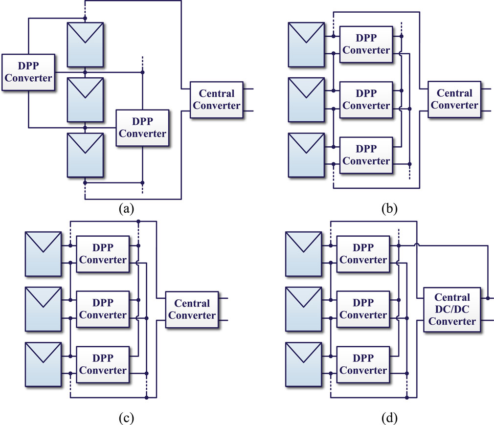
Figure 2. Typical differential power processing (DPP) architectures for distributed PV systems: (a) PV element to PV element architecture; (b) PV element to isolated port bus architecture; (c) PV element to non-isolated port (PV-NIP) bus architecture type I; (d) PV-NIP bus architecture type II.
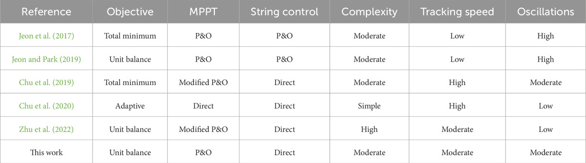
Table 1. Key features of different control schemes for the PV-NIP DPP architectures.
To achieve balanced distribution of the differential power and simple extraction of the maximum power, a unit power rating balancing (UPRB) scheme with DPP-converter-unit-level-independent MPPT control is proposed herein for the PV-NIP DPP architectures. To ensure bidirectional power transfer capability, various bidirectional DC-DC converters may be employed as the DPP units, e.g., dual active bridge (DAB) converters (Wang et al., 2021; Bu et al., 2022; Shi et al., 2022; Feng et al., 2025) and quasi-Z-source-based isolated bidirectional DC-DC converter (Kafle et al., 2019). Compared to the aforementioned bidirectional solutions, the flyback topology outperforms in simple configurations and requires fewer power switches, making it cost-effective and suitable for low-voltage applications. Accordingly, the bidirectional flyback topology is employed as the DPP converter and implemented in the PV-NIP bus DPP architecture, where the voltage gain of the flyback converter is easily adjusted by regulating the turns ratio of the transformer and matching the required voltage level of the bus. The proposed UPRB is an integrated perturbation and observation (P&O)-based MPPT controller in each DPP converter that maximizes the energy harvested from the PV modules; further, a unit balance-point tracking (UBPT) unit is employed to determine the optimal string current reference adaptively to mitigate the unbalanced differential power in the DPP units. Notably, the MPPT control at the DPP converter unit level is decoupled from the string-level current optimization. The implementation of the widely adopted P&O-based MPPT method herein aims to reduce control complexity. For better maximum energy yield, the P&O method may be replaced with any other advanced MPPT method. Both simulations and experiments were carried out in this work to validate the effectiveness of the proposed UPRB scheme. The remainder of this paper is organized as follows. Section 2 presents an analysis of the theoretical differential power distributions in the PV-NIP bus DPP architectures. The technical details of the proposed UPRB scheme are introduced in Section 3. The simulations and experimental validations are presented in Section 4 and Section 5, respectively, and the conclusions of the study are summarized in Section 6.
2 Theoretical power distribution in the PV-NIP DPP architecture
Compared to other DPP architectures, the type II PV-NIP bus DPP architecture offers better system efficiency and control flexibility; here, the DPP converter only transfers energy between its relative series-connected elements and the entire string, which offers the benefits of modularity and independent converter operating state. Accordingly, the type II PV-NIP bus DPP architecture shown in Figure 2d is employed in this work.
2.1 Generalized power distribution model
In a PV-NIP bus architecture with bidirectional DPP converter units, the direction of differential current flow according to Kirchhoff’s current law (KCL) depends on the differences between the string current and currents in the corresponding PV elements. As demonstrated in Figure 3a, when the current of the

Figure 3. Differential current paths of the
Accordingly, the system can be configured using a mathematical model to explain the relationships between the PV element current, string current, and differential current through basic ascension of each PV element with the operating current
Here, the conditions of the
The ideal differential power flowing through the
Then, the ideal total differential power
Considering the power rating,
When the string current
As the string current increases, in the region of between
With continued increase of the string current, the DPP converter with the most stressed differential power rating will change to the first converter unit whose string current is in the range of average of
If the string current increases beyond
In summary, for a lower string current value less than the average of
2.2 Power distribution in the example DPP system
In PV-NIP DPP architectures with odd or even numbers of PV elements and DPP converter units, as shown in Figures 4, 6, respectively, the differential power stress on each DPP converter can be calculated using the above approach. Assuming that there is no power loss during power transfer and that each PV element operates at its MPP with a very close MPP voltage, the theoretical differential power analysis can be carried out for the example architecture.
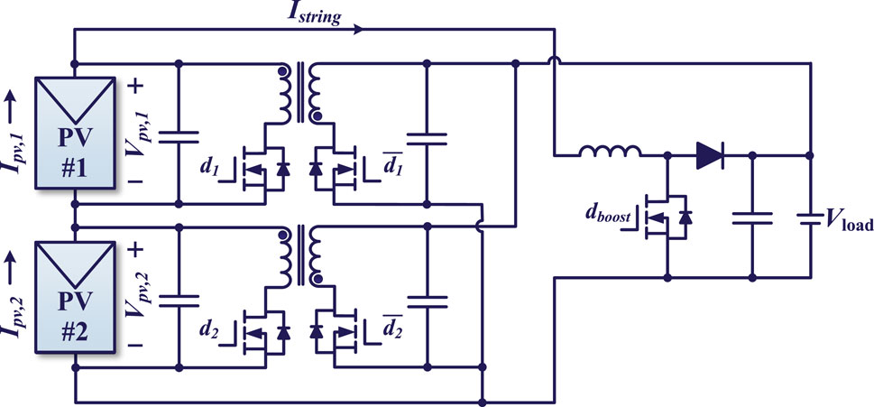
Figure 4. PV-NIP bus DPP architecture with even numbers (two) of PV elements and bidirectional flyback-based DPP converter units.
2.2.1 Example of a system with two PV elements
According to Equation 3, the total differential power for the DPP architecture with three PV elements shown in Figure 4 is given by Equation 9:
Assuming
To illustrate the differences in differential power obtained, a case study was conducted using the MSX-60 PV module, which has an MPP voltage of 17 V and MPP current of 3.5 A under standard test conditions. In the case study, the example is assumed under the mismatching condition, where the two PV elements are operated at unique MPPs with MPP currents of 1.4 A and 3.5 A for PV elements 1 and 2, respectively.
As demonstrated in Figure 5, the impacts of string current variations on the total differential power
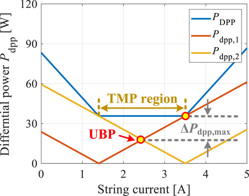
Figure 5. Impacts of string current variations on the total differential power of the system and DPP-converter-unit-level differential power of the example system shown in Figure 4. TMP: total minimum differential power; UBP: unit balance differential power.
2.2.2 Example of a system with three PV elements
The total differential power for a DPP architecture with three PV elements shown in Figure 6 is given by Equation 11:
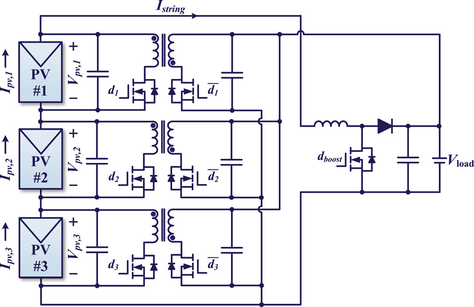
Figure 6. PV-NIP bus DPP architecture with odd numbers (three) of PV elements and bidirectional flyback-based DPP converter units.
Assuming
In this case, the example mismatches of the MPP currents in the three-element DPP system are 0.7 A, 2.8 A, and 3.5 A for PV elements 1, 2, and 3, respectively. As demonstrated in Figure 7, the impacts of string current variations on the total differential power
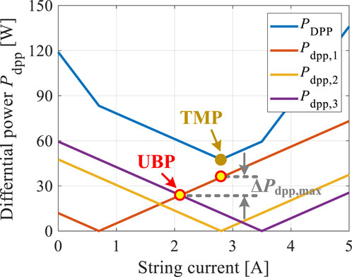
Figure 7. Impacts of string current variations on the total differential power of the system and DPP-converter-unit-level differential power of the example system shown in Figure 6. TMP: total minimum differential power; UBP: unit balance differential power.
3 Proposed UPRB scheme
Notably, the mitigation of unbalanced differential power can reduce uneven thermal distribution as well as the aging effect in relative converters, improving the lifetime of the DPP system (Zhu et al., 2022). In accordance with the above analysis, the unit-level differential power can be optimized sufficiently with minimal uneven distribution by regulating the string current to the optimal UBP point. Thus, a UPRB control scheme is proposed herein, whose block diagram is illustrated in Figure 8. The proposed scheme requires periodic measurement of the currents and voltages of each of the PV elements.
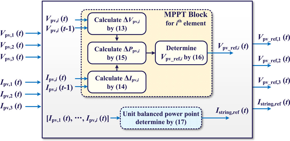
Figure 8. Control diagram of the proposed unit power rating balancing (UPRB) scheme.
3.1 MPPT block
To maximize the energy harvested from the PV modules, a P&O-based MPPT controller is integrated into each DPP converter. Based on periodic measurement of the PV voltage of each element, the change in voltage at the most recent sampling interval of the
where
Similarly, the current change in the
where
Hence, the power change in the
Accordingly, the voltage reference regulation for the
where
3.2 UBPT block
To mitigate the unbalanced differential power distribution among the DPP converter units, a differential UBPT unit is employed to determine the optimal string current reference adaptively. Based on the power rating analysis above, power balance is achieved at the midpoint of the PV string. To mitigate the oscillations induced by the P&O mechanism for string current reference optimization, the string current reference
To regulate the string current with fast response and high accuracy, a PI controller is employed to control the string current based on the reference calculated in Equation 17. If the optimization objective of the string current reference is with respect to the TMP,
Hence, in a PV-NIP DPP system with even number of PV elements, the TMP is obtained by tracking the UBP, as shown in Figure 5 for the example with two PV elements.
4 Simulations
The proposed control strategy was simulated in PSIM using the example system setup shown in Figure 4. The MSX-60 PV module with an MPP voltage of 17 V and MPP current of 3.5 A was used as the PV source under standard test conditions. Bidirectional flyback converters with a switching frequency of 50 kHz were employed as the DPP converter units. The perturbation interval for the unit-level P&O-based MPPT control was set to 0.04 s.
The irradiation was changed every 1 s to simulate unpredictable environmental conditions for evaluating the proposed control scheme. During the first second (Case I), the irradiation on PV elements 1 and 2 were 1,000 and 800
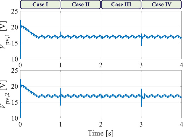
Figure 9. Simulation results of the PV element voltages under various shading scenarios.
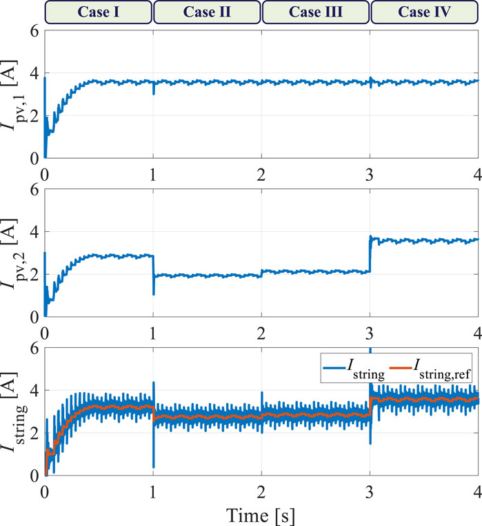
Figure 10. Simulation results of the PV element currents and string current under various shading scenarios.
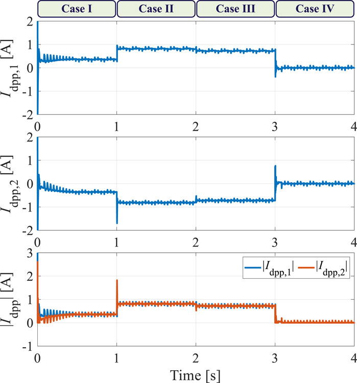
Figure 11. Simulation results of the differential currents flowing through the DPP converter units under various shading scenarios.
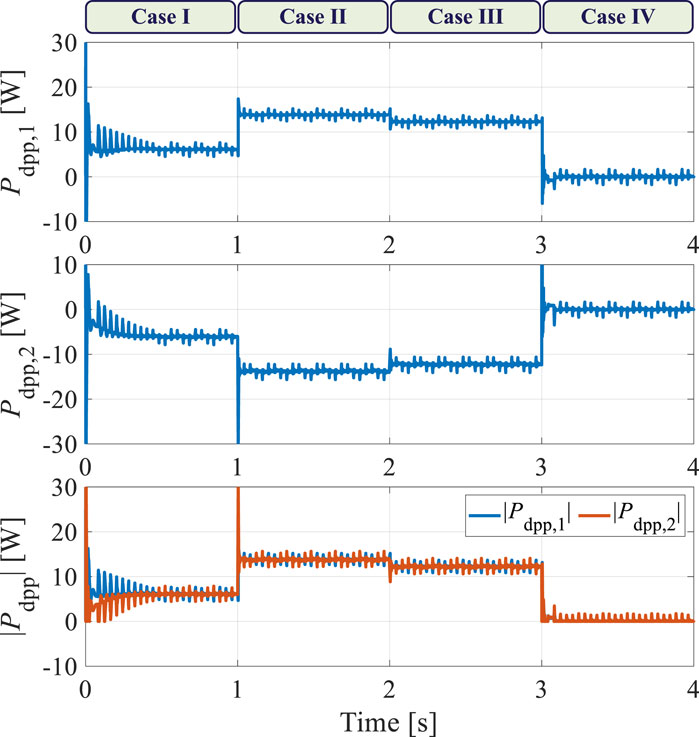
Figure 12. Simulation results of the differential power values processed by the DPP converter units under various shading scenarios.
5 Experimental validations
To verify the effectiveness of the proposed scheme, experiments were carried out with prototypes based on the PV-NIP DPP architecture shown in Figure 4. Considering the characteristics of the proposed control scheme, the power rating of the flyback-based DPP converter unit was designed to be 40 W with a switching frequency of 20 kHz to cover the worst possible range of shading mismatches. The transformer inductance in the flyback DPP unit is 300 µH. The centralized boost converter is rated at 200 W and has a switching frequency of 20 kHz. Here, the programmable DC supply (RIGOL DP832) serves as a controllable current source and is connected in parallel with the MSX-60 PV elements to mimic irradiance changes in the laboratory. The proposed scheme was implemented on the dSPACE DS1104 R&D Controller Board, and the experimental platform is illustrated in Figure 13.
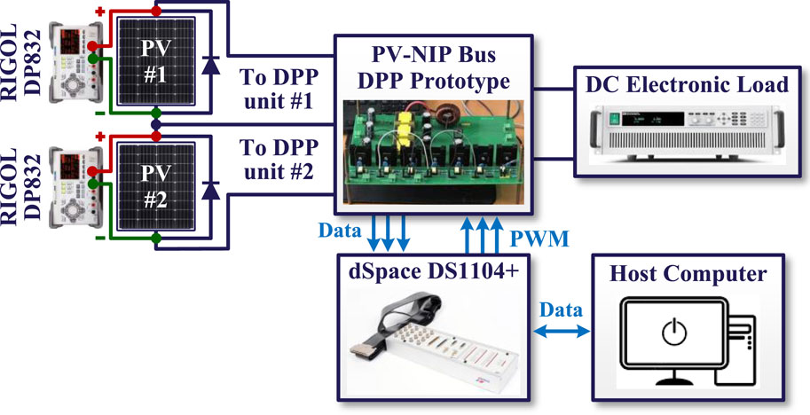
Figure 13. Diagram of the PV-NIP DPP experimental system.
The experimental setup comprises a simplified DPP architecture with two PV elements and two bidirectional flyback DPP converters. The sample time for the algorithm is 0.4 s, and the data are measured using voltage and current probes before being stored in a host computer. To evaluate the proposed control scheme, a step change in irradiation was initiated for PV element 2 at 14 s, while the irradiation on PV element 1 remained unchanged. The current through each PV element during the entire recording time is shown in Figure 14. When the irradiation on PV element 2 changed, the three-level oscillation observed at steady state was broken, and the current was regulated to the next steady state. During changes in irradiation, the string current changes in response to the changes in the PV elements, and the measured string current is the average of the unit currents. The tracking error between the string current and its reference is shown in Figure 15; here, the string current follows the changes in its reference under shading dynamics, and the tracking error is successfully restricted to the range of −0.05 A to 0.05 A. As shown in Figure 16, the differential power of each DPP converter unit can be balanced using the proposed method. Thus, the effectiveness of the proposed control scheme is validated through experiments under shading dynamics.
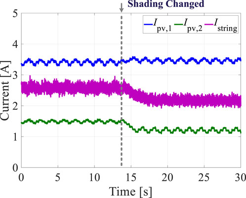
Figure 14. Experimental results of the PV element currents and string current under shading dynamics.
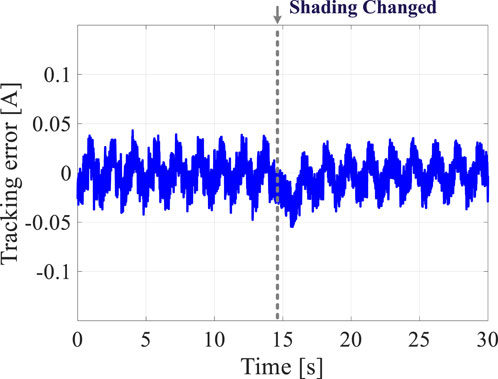
Figure 15. Experimental result of the tracking error between the string current and its reference under shading dynamics.
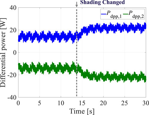
Figure 16. Experimental results of the differential power values processed by the DPP converter units under shading dynamics.
6 Conclusion
Unpredictable mismatch conditions, such as partial shading, manufacturing tolerances, thermal gradients, dissimilar aging, or dirt, can result in mismatched output characteristics of series-connected PV elements. DPP architectures are promising candidates for future PV generation systems as they help achieve higher efficiencies by processing only a portion of the full power generated while achieving the individual MPPs. In this work, we analyzed the differential power distributions in a bidirectional flyback-based PV-NIP bus DPP architecture. Then, we propose a UPRB scheme to reconfigure the differential power distributions among the unit converters with the aim of ensuring submodule-level optimization and enhancing the performance of the entire PV system. To achieve the individual MPPs of the PV elements, a P&O-based MPPT control is implemented in each DPP converter unit. To balance the power distribution among all DPP converter units in the system, UBPT control was implemented to optimize the string current. The proposed control scheme was verified using both simulations and experiments under shading dynamics and shown to reliably balance the differential power distribution.
Data availability statement
The raw data supporting the conclusions of this article will be made available by the authors without undue reservation.
Author contributions
JN: data curation, formal analysis, funding acquisition, methodology, validation, writing – original draft, and writing – review and editing. ZZ: formal analysis, methodology, software, and writing – review and editing. YZ: formal analysis, funding acquisition, methodology, validation, writing – original draft, and writing – review and editing.
Funding
The author(s) declare that financial support was received for the research and/or publication of this article. This work was supported by the National Key R&D Program of China (no. 2024YFB4207000), Postdoctoral Fellowship Program of China Postdoctoral Science Foundation (no. GZB20240644), and Zhejiang Provincial Key R&D Program (no. 2024C01242(SD2)).
Conflict of interest
Authors JN and ZZ were employed by PowerChina Huadong Engineering Cooperation Limited.
The remaining author declares that the research was conducted in the absence of any commercial or financial relationships that could be construed as a potential conflict of interest.
Generative AI statement
The authors declare that no Generative AI was used in the creation of this manuscript.
Publisher’s note
All claims expressed in this article are solely those of the authors and do not necessarily represent those of their affiliated organizations, or those of the publisher, the editors and the reviewers. Any product that may be evaluated in this article, or claim that may be made by its manufacturer, is not guaranteed or endorsed by the publisher.
References
Aifan, G., Alsulami, A., Alhussainy, A. A., Allehyani, A., Alturki, Y. A., Alghamdi, S. M., et al. (2024). A comparison of several maximum power point tracking algorithms for a photovoltaic power system. Front. Energy Res. 12, 1413252. doi:10.3389/fenrg.2024.1413252
Ali, S., El Iysaouy, L., Lahbabi, M., Boujoudar, Y., Alharbi, S. J., Azeroual, M., et al. (2023). A matlab-based modelling to study and enhance the performance of photovoltaic panel configurations during partial shading conditions. Front. Energy Res. 11, 1169172. doi:10.3389/fenrg.2023.1169172
Amaral da Luz, C. M., Vicente, E. M., Tofoli, F. L., and Ribeiro, E. R. (2023). Differential power processing architecture to increase energy harvesting of photovoltaic systems under permanent mismatch. Sol. Energy 263, 111940. doi:10.1016/j.solener.2023.111940
Blaabjerg, F., Yang, Y., Kim, K. A., and Rodriguez, J. (2023). Power electronics technology for large-scale renewable energy generation. Proc. IEEE 111, 335–355. doi:10.1109/JPROC.2023.3253165
Bu, Q., Wen, H., Zhu, Y., Shi, H., and Chu, G. (2022). “Transient bias suppression optimization for bidirectional 2/3-level dc-dc converters,” in 2022 International Power Electronics Conference (IPEC-Himeji 2022- ECCE Asia), Himeji, Japan, 15–19 May, 2022, 2647–2652. doi:10.23919/ipec-himeji2022-ecce53331.2022.9807089
Celik, O., Teke, A., and Tan, A. (2018). Overview of micro-inverters as a challenging technology in photovoltaic applications. Renew. Sustain. Energy Rev. 82, 3191–3206. doi:10.1016/j.rser.2017.10.024
Chu, G., Bu, Q., and Yang, M. (2024). “Steady-state analysis of the constant power region in distributed maximum power point tracking architecture with photovoltaic applications,” in 2024 IEEE Energy Conversion Congress and Exposition (ECCE), Phoenix, AZ, United States, 20-24 October, 2024 (IEEE), 475–481.
Chu, G., Wen, H., Hu, Y., Jiang, L., Yang, Y., and Wang, Y. (2020). Low-complexity power balancing point-based optimization for photovoltaic differential power processing. IEEE Trans. Power Electron. 35, 10306–10322. doi:10.1109/TPEL.2020.2977329
Chu, G., Wen, H., Jiang, L., Hu, Y., and Li, X. (2017). Bidirectional flyback based isolated-port submodule differential power processing optimizer for photovoltaic applications. Sol. Energy 158, 929–940. doi:10.1016/j.solener.2017.10.053
Chu, G., Wen, H., Yang, Y., and Wang, Y. (2019). Elimination of photovoltaic mismatching with improved submodule differential power processing. IEEE Trans. Ind. Electron. 67, 2822–2833. doi:10.1109/TIE.2019.2908612
Chu, G., Wen, H., and Zhu, Y. (2022). Advanced distributed maximum power point tracking technology. United Kingdom: Institution of Engineering and Technology, 127–191. Available online at: https://digital-library.theiet.org/doi/10.1049/pbpo228e_ch6.
Dong, P., Wen, H., Chu, G., Yang, Y., and Wang, Y. (2019). Power rating analysis and protection for photovoltaic-isolated port based differential power processing systems. Sol. Energy 193, 458–472. doi:10.1016/j.solener.2019.09.092
Feng, Z., Wen, H., Han, X., Wang, G., Zhu, Y., and Rodrigues, J. (2025). A deep reinforcement learning framework for 3l-npc-dab converters with multiple-degree-of-freedom phase-shift control. IEEE Trans. Transp. Electrification 1, 3545834. doi:10.1109/TTE.2025.3545834
Jeon, Y., and Park, J. (2019). Unit-minimum least power point tracking for the optimization of photovoltaic differential power processing systems. IEEE Trans. Power Electron. 34, 311–324. doi:10.1109/TPEL.2018.2822289
Jeon, Y-T., Lee, H., Kim, K. A., and Park, J-H. (2017). Least power point tracking method for photovoltaic differential power processing systems. IEEE Trans. Power Electron. 32, 1941–1951. doi:10.1109/TPEL.2016.2556746
Jeong, H., Lee, H., Liu, Y.-C., and Kim, K. A. (2019). Review of differential power processing converter techniques for photovoltaic applications. IEEE Trans. Energy Convers. 34, 351–360. doi:10.1109/TEC.2018.2876176
Kafle, Y. R., Hasan, S. U., and Town, G. E. (2019). Quasi-z-source based bidirectional dc-dc converter and its control strategy. Chin. J. Electr. Eng. 5, 1–9. doi:10.23919/CJEE.2019.000001
Khan, O., and Xiao, W. (2017). Review and qualitative analysis of submodule-level distributed power electronic solutions in pv power systems. Renew. Sustain. Energy Rev. 76, 516–528. doi:10.1016/j.rser.2017.03.073
Li, D., Li, J., and Wang, N. (2021). A novel technique based on peafowl optimization algorithm for maximum power point tracking of pv systems under partial shading condition. Front. Energy Res. 9, 801571. doi:10.3389/fenrg.2021.801571
Li, X., Zhu, Y., Wen, H., Du, Y., and Xiao, W. (2022). Reference-voltage-line-aided power incremental algorithm for photovoltaic gmppt and partial shading detection. IEEE Trans. Sustain. Energy 13, 1756–1770. doi:10.1109/TSTE.2022.3174614
Lv, R., Zhu, Y., and Yang, Y. (2024). Robust design of perturb and observe maximum power point tracking for photovoltaic systems. IEEE Trans. Industry Appl. 60, 6547–6558. doi:10.1109/TIA.2024.3397971
Nunes, H. G. G., Morais, F. A. L., Pombo, J. A. N., Mariano, S. J. P. S., and Calado, M. R. A. (2022). Bypass diode effect and photovoltaic parameter estimation under partial shading using a hill climbing neural network algorithm. Front. Energy Res. 10, 837540. doi:10.3389/fenrg.2022.837540
Olalla, C., Deline, C., Clement, D., Levron, Y., Rodriguez, M., and Maksimovic, D. (2015). Performance of power-limited differential power processing architectures in mismatched pv systems. IEEE Trans. Power Electron. 30, 618–631. doi:10.1109/TPEL.2014.2312980
Ramli, M. Z., and Salam, Z. (2019). Performance evaluation of dc power optimizer (DCPO) for photovoltaic (PV) system during partial shading. Renew. Energy 139, 1336–1354. doi:10.1016/j.renene.2019.02.072
Refaat, A., Khalifa, A.-E., Elsakka, M. M., Elhenawy, Y., Kalas, A., and Elfar, M. H. (2023). A novel metaheuristic mppt technique based on enhanced autonomous group particle swarm optimization algorithm to track the gmpp under partial shading conditions - experimental validation. Energy Convers. Manage. 287, 117124. doi:10.1016/j.enconman.2023.117124
Shenoy, P. S., Kim, K. A., Johnson, B. B., and Krein, P. T. (2013). Differential power processing for increased energy production and reliability of photovoltaic systems. IEEE Trans. Power Electron. 28, 2968–2979. doi:10.1109/TPEL.2012.2211082
Shi, H., Wen, H., Chen, G., Bu, Q., Chu, G., and Zhu, Y. (2022). Multiple-fault-tolerant dual active bridge converter for dc distribution system. IEEE Trans. Power Electron. 37, 1–1760. doi:10.1109/TPEL.2021.3106508
Uno, M., Sato, H., and Oyama, S. (2022). Switched capacitor-based modular differential power processing architecture for large-scale photovoltaic systems under partial shading. IEEE Trans. Energy Convers. 37, 1–1556. doi:10.1109/TEC.2022.3157656
Wang, Y., Wen, H., Zhu, Y., Shi, H., Bu, Q., Hu, Y., et al. (2021). Minimum-current-stress scheme of three-level dual-active-bridge dc–dc converters with the particle swarm optimization. IEEE Trans. Transp. Electrification 7, 2067–2084. doi:10.1109/TTE.2021.3073362
Yılmaz, M., Kaleli, A., and Çorapsız, M. F. (2023). Machine learning based dynamic super twisting sliding mode controller for increase speed and accuracy of mppt using real-time data under pscs. Renew. Energy 219, 119470. doi:10.1016/j.renene.2023.119470
Zhu, Y., Wen, H., Chu, G., Wang, X., Peng, Q., Hu, Y., et al. (2022). Power-rating balance control and reliability enhancement in mismatched photovoltaic differential power processing systems. IEEE Trans. Power Electron. 37, 879–895. doi:10.1109/TPEL.2021.3094220
Zhu, Y., Wen, H., Tafti, H. D., Wang, G., Bu, Q., Chu, G., et al. (2024a). Novel fast-speed partial-shading-tolerant flexible power point tracking for photovoltaic systems with explicit key points estimation. IEEE Trans. Sustain. Energy 15, 466–485. doi:10.1109/TSTE.2023.3303456
Zhu, Y., Yang, Y., Blaabjerg, F., and Lv, R. (2024b). “A simple global maximum power point tracking scheme with region segmentation for partially shaded PV modules,” in 2024 IEEE 15th International Symposium on Power Electronics for Distributed Generation Systems (PEDG), Luxembourg, 18 September, 2024 (IEEE), 1–6.
Keywords: differential power processing, photovoltaic system, energy harvesting, unit power rating balancing, efficiency
Citation: Ni J, Zhao Z and Zhu Y (2025) Unit power rating balancing for differential-power-processing-based distributed photovoltaic systems. Front. Energy Res. 13:1611573. doi: 10.3389/fenrg.2025.1611573
Received: 14 April 2025; Accepted: 28 April 2025;
Published: 29 May 2025.
Edited by:
Wenping Zhang, Tianjin University, ChinaReviewed by:
Qinglei Bu, Xi’an Jiaotong-Liverpool University, ChinaLunbo Deng, Southwest Jiaotong University, China
Copyright © 2025 Ni, Zhao and Zhu. This is an open-access article distributed under the terms of the Creative Commons Attribution License (CC BY). The use, distribution or reproduction in other forums is permitted, provided the original author(s) and the copyright owner(s) are credited and that the original publication in this journal is cited, in accordance with accepted academic practice. No use, distribution or reproduction is permitted which does not comply with these terms.
*Correspondence: Yinxiao Zhu, eWlueGlhby56aHVAemp1LmVkdS5jbg==