 Xinkai Li
 Xiaojiang Guo1,2
 Xin Shen
- 1Offshore Wind Energy Department, Huaneng Clean Energy Research Institute, Beijing, China
- 2Research and Development Center of National Energy Offshore Wind Power Engineering and Operation Technology, Beijing, China
- 3School of Mechanical Engineering, Shanghai Jiao Tong University, Shanghai, China
Introduction: Tandem dual-rotor wind turbines achieve efficient wind energy capture through aerodynamic coupling between upstream and downstream rotors. However, the influence mechanism of rotor spacing on complex flow fields and turbine performance remains unclear.
Methods: Aiming at this problem, a high-precision computational fluid dynamics (CFD) method was adopted to construct a physical model of dual-rotors with real blade geometry. Using global structural grid meshing and the Transition-SST turbulence model, the flow characteristics of air around the rotors were systematically investigated under six typical spacings ranging from 0.2 D to 2.0 D (D is the diameter of the front rotor).
Results and discussion: The study found that as the spacing increases, the power of the front rotor increases logarithmically, while the power of the rear rotor gradually decreases. The total power of the dual-rotors continues to rise, showing different growth rates before and after 0.5 D. Flow field analysis indicates that the wake blockage effect of the front rotor on the rear rotor is significant at small spacings, while the wake velocity recovers more fully and the turbulence mixing effect enhances at large spacings. This research reveals the regulation law of rotor spacing on aerodynamic interference effects, provides key parameter basis for optimizing wind energy capture and designing structural loads of dual-rotor turbines, and fills the research gap on the influence of tandem dual-rotor spacing on flow field characteristics.
1 Introduction
1.1 Research background and significance
With the development of wind power technology towards large-scale and high-efficiency, traditional single-rotor wind turbines face problems such as increased structural loads, aeroelastic stability risks, and higher costs due to excessively long blades. The tandem dual-rotor structure, which arranges upstream and downstream rotors on the same axis, realizes two-stage axial conversion of wind energy. Theoretically, it can break through the Betz limit (0.593) of single rotors, featuring higher power density and lower swept area requirements, thus becoming a promising technical solution. However, the upstream and downstream rotors operate in a strongly coupled flow field, with complex interference between the wake of the front rotor and the inflow of the rear rotor. As a key design parameter, rotor spacing directly affects the flow field structure, wind energy capture efficiency, and turbine load characteristics. While previous studies (e.g., Kubo et al. (Kubo and Kanemoto, 2008)) primarily focused on rotor rotation direction and blade configuration, the aerodynamic coupling mechanism under varying rotor spacing remains poorly understood. This study uniquely addresses this gap by systematically investigating six spacing configurations (0.2D–2.0D) to establish an optimal design threshold. It is urgent to reveal the aerodynamic coupling mechanism under spacing regulation.
1.2 Research status and challenges
The blade length of large wind turbines has now exceeded 100 m (IRENA. Renewable Technology Innovation Indicators: Mapping progress in costs, 2022; Lu et al., 2025). Although material and design advancements have lightweighted blades to some extent, blade mass still increases superlinearly with rotor diameter (Veers et al., 2003). The huge blade mass leads to increased rotor inertia, which is unfavorable for the control of wind turbines and wind farms; low vibration natural frequency, prone to resonance and threatening structural safety; increased flexibility of ultra-long blades, higher risk of aeroelastic instability, and significantly increased design, manufacturing, and installation costs, posing severe challenges to the low-cost, high-efficiency, and safe operation of wind power. These issues hinder the technical route of simply increasing blade length to form larger-diameter rotors for turbine scaling up, and impede the process of wind power becoming more cost-competitive.
In addition to increasing rotor diameter, other approaches to scaling up horizontal-axis wind turbines include new types with tandem dual-rotors, multi-rotors, diffusers, etc., which improve single unit power by enhancing wind energy utilization efficiency. The tandem dual-rotor structure, composed of two coaxial rotors in a single nacelle, can rotate in the same or opposite directions, achieving two-stage conversion of wind energy in the axial direction. It has advantages such as relatively simple structure, high power generation efficiency, and better compatibility with the existing industrial chain, making it the easiest to put into practical application among the above concepts. Although the dual-rotor concept was proposed to solve problems such as low aerodynamic efficiency at the blade root and rotational speed loss in the wake of single rotors, this structure has a higher theoretical maximum aerodynamic efficiency and requires a smaller rotor swept area to achieve the same power level, thus potentially becoming a more cost-effective wind power solution in the future.
Currently, the tandem dual-rotor wind turbine concept has not formed a mature design, and different researchers use the same physical structure for different purposes. For example, Ushiyama et al. (1996)) demonstrated forward and reverse rotation schemes for dual-rotors, and wind tunnel tests showed that forward rotation of dual-rotors can improve the self-starting performance of wind turbines, while reverse rotation can increase the relative speed of the generator. Kanemoto and Galal (2006) proposed a method to stabilize the power generation of wind turbines and improve their performance at low wind speeds by making the rear rotor switch between forward and reverse rotation with wind speed. Appa (2002) used a dual-rotor structure to increase the single unit power of wind turbines, while Cho et al. (2017) achieved fast yaw response of wind turbines through the dual-rotor structure. These studies indicate that dual-rotor wind turbines have various utilizable characteristics, but explaining the internal mechanisms behind these characteristics requires starting from the aerodynamic aspect.
The two rotors of tandem dual-rotor wind turbines operate upstream and downstream in the flow field, in the upstream induction region or near-field wake of the rotor, where the flow environment is affected by the local flow effects of the blades, with unsteady effects such as blade interference and three-dimensional vortex system interference (Porté et al., 2020). The main aerodynamic components of tandem dual-rotors are two coaxial forward or reverse rotating rotors. To achieve the aerodynamic design of the dual-rotor structure, research on dual-rotor flow mainly includes using momentum theory models to determine the theoretical maximum aerodynamic efficiency realization method of tandem dual-rotors, analyzing the main factors affecting performance and flow mechanisms for actual dual-rotors, and developing fast and accurate methods for predicting the aerodynamic performance of dual-rotors, so as to provide guidance and tools for the aerodynamic layout design and main parameter selection of dual-rotors.
Wind turbine rotors convert the kinetic energy in wind into the mechanical energy of rotor rotation to drive the generator for power generation. The research and modeling of wind energy utilization principles of wind turbines from a momentum perspective began in the mid-to-late 19th century, first established by Rankine, Froude, etc. with the one-dimensional momentum theory for wind turbines (Sø rensen, 2011). This theory assumes inviscid flow, infinite blades, non-rotating, and uniformly distributed loads, and can derive that the induced velocity at the point where the downstream pressure of the rotor is fully recovered is twice the induced velocity on the rotor. According to momentum theory, the maximum power coefficient of a single-rotor wind turbine Cpmax≈0.593, this result is also known as the Betz limit (Hansen, 2008), reflecting the theoretical upper limit of the proportion of kinetic energy that the rotor can obtain from the wind. The power coefficient of an actual single-rotor wind turbine is affected by rotor rotation, flow field viscosity, and blade performance, and can only approach this value continuously.
The classic momentum theory model does not specify the form and number of ideal rotors. Therefore, if a dual-rotor wind turbine is regarded as a single actuator disk with a suitable reference area for analysis, its power still will not exceed the Betz limit of wind turbines. However, this reference area is difficult to define and cannot reflect the size of the actual wind turbine rotor. To obtain meaningful conclusions for dual-rotors, it is necessary to select the swept area of the larger rotor as the reference area and model the front and rear rotors respectively. In 1983, Newman (Newman, 1983) first studied the wind energy utilization principle of dual actuator disks for vertical-axis wind turbines. In his theoretical analysis, the fluid flowing through the dual-rotors was divided into inner and outer two flow tubes as shown in Figure 1. By deriving the relationship between momentum and velocity respectively, it was pointed out that the maximum power coefficient that the dual actuator disk structure can achieve is 16/25 or 0.64. Further generalization (Newman, 1986) shows that increasing the number of rotors to infinity can only utilize no more than 2/3 of the wind energy. This theory guides the aerodynamic design of vertical-axis wind turbines but introduces two unreasonable assumptions, namely,:
1. The pressure between the two rotors recovers to atmospheric pressure, that is, the pressure at the neutral plane between the rotors shown in Figure 1 is atmospheric pressure. Under this assumption, the momentum theory of single rotors is applicable to any rotor in the dual-rotors, and the fully developed wake of the front rotor can be directly used as the inflow of the rear rotor for analysis, ignoring the specific process of upstream and downstream flow interference at different wake development stages under finite spacing;
2. The velocity on the front rotor is uniform in the radial direction, that is, V1 = V3 in Figure 1. This assumption ignores the possible influence of the existence of the downstream rotor on the spanwise velocity distribution of the upstream wind turbine. Although a uniform velocity distribution can be obtained through aerodynamic design, it is an unnecessary restriction for dual-rotors that need to obtain the maximum aerodynamic efficiency.
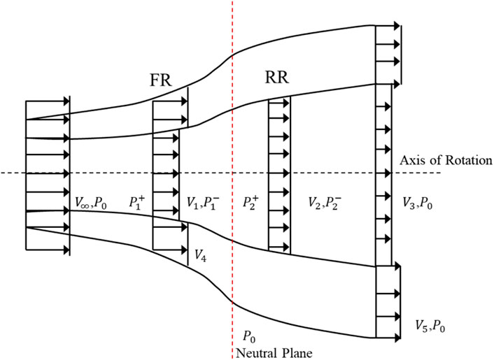
Figure 1. Schematics of DRWT flow structure and design with maximum coefficient of power (KMUTT Sustainable Development, 2008).
Based on the above analysis, it can be seen that the application of these two assumptions actually leads to the conclusion in Newman’s momentum theory that there is no form of aerodynamic interference between the two rotors.
Aiming at assumption (2), (Kmutt Sustainable Development, 2008), and (Agrawal, 2010) respectively assumed different axial velocities for the inner and outer flow regions of the front rotor flow and carried out optimization solutions. Their conclusions show that the maximum power coefficient of the tandem dual-rotor structure can reach 0.814, much higher than the 0.64 result proposed by Newman. The best design should make 58.2% of the area or 76.2% of the radius of the front rotor not decelerate the air at all, and the corresponding wind turbine concept is shown in Figure 1.
Sundararaju et al. (2017) further canceled assumption (1) on the basis of the above work, took the coupled velocity as a variable, and established a model of the power coefficient of dual-rotors and the momentum balance relationship in the flow field. His analysis also shows that the limit power coefficient of dual-rotors reaches 0.814. Starting from this result, taking the flow field velocity at this time as the boundary condition, the flow of dual actuator disks was numerically simulated, the relationship between the area proportion of the internal coupling region on the front rotor and the rotor spacing was explored, and the rotor spacing for obtaining the maximum power coefficient was calculated to be 2.8 times the diameter. His research also shows that for dual-rotor wind turbines, momentum theory analysis cannot obtain the general law of induced velocity in the wake and induced velocity on the rotor, and unknowns must be set separately in the derivation of the dual-rotor power coefficient for processing.
Momentum theory links the kinetic energy in the flow field during the operation of dual-rotor wind turbines with the pressure drop on the rotors and provides the theoretical limit efficiency that the dual-rotor structure can achieve, guiding the aerodynamic layout of dual-rotors. However, due to the complex aerodynamic coherence characteristics of dual-rotors, momentum theory is not sufficient to fully describe the flow field characteristics of dual-rotors; this theory does not involve specific blade structures, so it cannot consider the influence of actual rotor design, operating parameters, etc. on the aerodynamic performance of dual-rotors.
To clarify the specific advantages and performance improvements of the dual-rotor concept compared with traditional single-rotor wind turbines and guide the selection of design parameters for dual-rotors, it is necessary to study the aerodynamic characteristics of actual dual-rotor wind turbines. The main research methods for dual-rotor wind turbines currently include wind tunnel and prototype tests, numerical simulation, and theoretical analysis based on vortex models, and the research content covers multiple aspects such as dual-rotor concept design, key parameter influence, and flow mechanism research.
Kubo et al. (Kubo and Kanemoto, 2008) from Kyushu Institute of Technology in Japan established a test bench for dual-rotor wind turbines and carried out wind tunnel tests on dual-rotor performance. Their conclusion is that under the same rotational speed, the power provided by dual-rotors is higher than that of single rotors, the optimal diameter ratio is 0.84, and the spacing should be as small as possible. Gregg et al. (Gregg et al., 2009) designed the shape of the rear rotor according to the wake rotation of the front rotor, but wind tunnel tests showed that the combination of front and rear rotors with this design had no performance advantage over two identical rotors. (Li et al., 2011; Li et al., 2013) studied the aerodynamic performance of small counter-rotating dual-rotor wind turbines and pointed out that the existence of the front rotor will increase the power of the rear rotor, and changing the rotor spacing, pitch angle, and rotational speed can increase the power coefficient of the wind turbine by 40%–50% compared with single rotors. Lipian et al. (Lipian et al., 2019) compared and studied the improvement of aerodynamic performance by diffuser, dual-rotor, and diffuser-equipped dual-rotor wind turbines, and pointed out that dual-rotors can reduce the thrust on a single rotor, lower the optimal tip speed ratio, and expand the optimal operation range. For open-structure dual-rotors, the power can be increased by 11%–13%, but for closed wind turbines with diffusers, it can only be increased by 4%–5%.
The research team of Professor Hu Hui from Iowa State University in the United States (Yuan et al., 2013; Ozbay et al., 2014; Yuan et al., 2014; Ozbay et al., 2015; Wang et al., 2018) carried out experimental research on the pre-rotation effect in the wake of wind turbines and found that counter-rotating wind turbines in the near-field wake have obvious power-increasing effects, and based on this, carried out experimental exploration on the wake of tandem dual-rotor wind turbines. Their research shows that counter-rotating dual-rotor wind turbines can utilize the rotational energy in the wake, but their static and dynamic aerodynamic loads also increase accordingly, which may lead to an increase in installation costs. Compared with single-rotor wind turbines, the tip vortices in the wake of dual-rotors are stronger and break earlier, the turbulence intensity in the wake increases, and the velocity recovery is faster. Wei et al. (2017) further carried out detailed capture of the axial and tangential velocities and vortex structures of the flow field of the dual-rotor system through PIV based on the test bench of Kubo et al. (Kubo and Kanemoto, 2008). Their analysis shows that the direction of the airflow rotation speed changes when passing through the front and rear rotors, and increasing the tip speed ratio can weaken the vortex intensity in the wake.
Due to the limitations of test conditions, wind tunnel tests generally can only carry out research on small wind turbine models. Full-scale research on large dual-rotor wind turbines mainly uses numerical research methods, namely, computational fluid dynamics (CFD) and vortex methods. Since these two methods directly solve the flow field distribution in space to different degrees, more flow details can be obtained through post-processing, and they are generally used as supplements to experimental results.
The vortex method simplifies the flow field of wind turbines into the development of vortex wakes and the superposition of vortex-induced velocities, enabling relatively fast flow field simulation. Lee et al. (2010) from Seoul National University compared the 2-blade, 4-blade, and 2 × 2-blade counter-rotating dual-rotor arrangements of the NREL Phase VI wind turbine through the free wake vortex lattice method. The calculation results show that the power of dual-rotors is 30% higher than that of the 2-blade single rotor, but not as high as that of the 4-blade single rotor, and the contribution of counter-rotation to reducing wake rotation speed loss to the overall performance is not obvious. In 2013, the team used the same method to calculate the counter-rotating dual-rotor structure composed of two MEXICO rotors. The results show that as the rotor spacing increases, the power of the front and rear rotors increases and decreases respectively, the total power remains basically unchanged, and it is pointed out that the BEM theory that does not consider the interaction between rotors is only applicable in a very small range (Lee et al., 2013). Slew et al. (2016) analyzed the combination of two Phase VI rotors and showed that if the radius of the front rotor is scaled to 5m, a 76% power increase can be achieved at a spacing of 0.5 m. The front auxiliary rotor reduces the angle of attack distribution inside the rear rotor, and it is pointed out that while achieving a small spacing, the limitations of the actual mechanical structure should be considered.
The CFD method directly solves the Navier-Stokes equations governing fluid motion. Due to the large scale of wind turbines and strong unsteady effects, directly modeling the blades of two rotors for solution requires high computational resources, so the rotor structure is often simplified through the actuator method. The actuator method only focuses on the wake of the wind turbine and reduces the computational load of flow field solution by equivalent the flow around the actual blades to the volume force applied to the flow field at the blade position. To consider the unsteady interference when the blades pass each other and the influence of tip vortices, the existing research generally uses the actuator line method that considers the actual number of blades to simulate dual-rotors (Shen et al., 2007). from the Technical University of Denmark realized the solution of the flow field of dual-rotor wind turbines by simplifying the blades with the actuator line method, pointed out that the performance of dual-rotors is better at low wind speeds, and calculated through the actual wind farm wind resource situation that the annual total power generation of dual-rotors can be 43.5% higher than that of single rotors (Rosenberg et al., 2014). from Iowa State University proposed a dual-rotor solution for the problem of poor aerodynamic performance at the blade root of the NREL 5 MW rotor, selected the size of the front auxiliary rotor through RANS, and simulated the flow field through the actuator line-LES method. The two results respectively show that the dual-rotor power is 7% and 4.6% higher than that of the original wind turbine. Based on the same method, (Moghadassian et al., 2016), simulated the operation status of this design under atmospheric boundary layer wind conditions and further pointed out that dual-rotors enhance the mixing effect between the wake and the undecelerated atmosphere and increase the turbulence intensity. Power and loads of wind turbines were also observed to fluctuate at the blade passing frequency in the simulation results. (Vasel-be-hagh and Archer, 2017). simulated wind farms with single rotors and counter-rotating dual-rotors and found that using dual-rotors can increase the power of the entire wind farm by 22.6%, but it also brings greater power fluctuations and tower fatigue loads.
For smaller-scale wind turbines, there is an opportunity to carry out refined simulation of the computational domain with actual blade structures. (Zhou and Yang, 2012). studied the influence of the number of rear rotor blades on the aerodynamics of front and rear rotors and pointed out that increasing the number of rear rotor blades can reduce the starting influence on the front rotor and increase the total power, but it will also lead to an increase in turbulence intensity and a decrease in stability. (Sun and Jianfeng, 2019). simulated the co-rotating NREL Phase VI dual-rotor wind turbine and found that the dual-rotor power gradually decreases when the rotor phase angle is between 30° and 75°. (Ai et al., 2020). carried out numerical simulation on the dual-rotor tidal current turbine and found that turbulence intensity is an important factor affecting the flow field distribution of dual-rotors. (Li et al., 2018). pointed out through high-precision simulation with the lattice Boltzmann method that the power-increasing mechanism of small dual-rotors includes not only the utilization of energy in the wake but also the high turbulence intensity in the front rotor wake inhibiting blade flow separation and the higher pressure drop of the front and rear rotors together. This also indicates that for the dual-rotor structure, the influence of either rotor on the other cannot be ignored, and the coupling effect between dual-rotors must be considered in the initial aerodynamic design of dual-rotors.
Table 1 lists the conclusions of some literature on the maximum power coefficient of dual-rotors and the influence of spacing. It can be seen from the table that the conclusions of different literature on the performance improvement of dual-rotor structures and the influence of different parameters of dual-rotors on aerodynamic performance are significantly different, and there is currently no consensus in the academic community on the performance improvement of dual-rotor structures for wind turbines and the influence of different parameters of dual-rotors on aerodynamic performance.
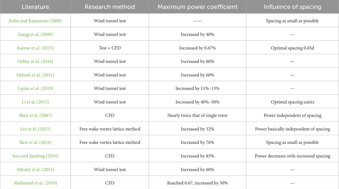
Table 1. Conclusions of some literature on the maximum power coefficient of dual-rotors and the influence of spacing.
1.3 Research objectives
In the above research on the aerodynamic characteristics of dual-rotors, there is no public report on the study of the influence of dual-rotor spacing on flow field interference characteristics. During the operation of dual-rotor turbines, the complex flow environment leads to strong flow coherence between rotors, making tandem dual-rotors show different aerodynamic characteristics from isolated single rotors or single-rotor wind turbines operating in the far-field wake of wind farms. The academic and industrial circles still do not have a clear understanding of the aerodynamic characteristics of tandem dual-rotors, especially the complex turbulent flow field between dual-rotors under different spacing conditions. Therefore, carrying out research on the influence of dual-rotor spacing on the complex flow field characteristics of dual-rotors is of great significance.
2 Numerical methods and validation
2.1 Numerical methods
Unsteady numerical calculations were performed, and the finite volume method was used to discretize the control equations. The second-order central difference scheme was adopted for spatial discretization, and the SIMPLE algorithm was used for pressure-velocity coupling. The Transition-SST turbulence model was selected due to its capability to accurately resolve boundary layer transitions and capture flow separation effects, which are critical for analyzing rotor wake interactions. The global domain was meshed with structural grids. By solving the complex turbulent flow field between dual-rotors, the influence of the radius ratio of the two rotors on the overall aerodynamic performance of the turbine was studied.
This study used the Sliding Mesh Method for unsteady transient calculations to accurately capture the unsteady turbulent interference effects between the two rotors. The computational domain is divided into a static domain and two independent rotational domains (including the front and rear rotors). The rotating domain and the static domain are connected through a sliding interface, allowing the grid to slide relative to each other at the interface while ensuring continuous transmission of flow field parameters (velocity, pressure, turbulence). Using a transient solver based on the finite volume method, directly solve the unsteady Navier Stokes equations. The time discretization adopts a second-order implicit format, and the flux at the slip interface is dynamically updated through grid interpolation.
2.2 Single-rotor numerical method validation
A 1.5 MW wind turbine with a rotor diameter of 77 m was selected for single-rotor method validation. The entire computational domain was meshed with structural grids. The single-rotor grid division is shown in Figure 2, with a total of 4.6 million grids, of which the Rotor domain has 2.8 million grids and the Far domain has 1.8 million grids. The calculation grid is shown in Figure 2.
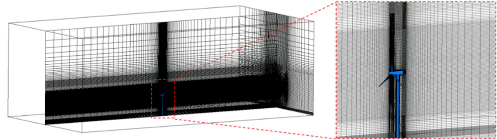
Figure 2. Calculation grid of single-rotor wind turbine.
Boundary conditions: Figure 3 shows the computational domain and boundary condition settings, using velocity inlet and pressure outlet boundary conditions. The bottom surface, blades, and tower nacelle are given no-slip wall surfaces, and the two sides and top surface are given open boundaries.
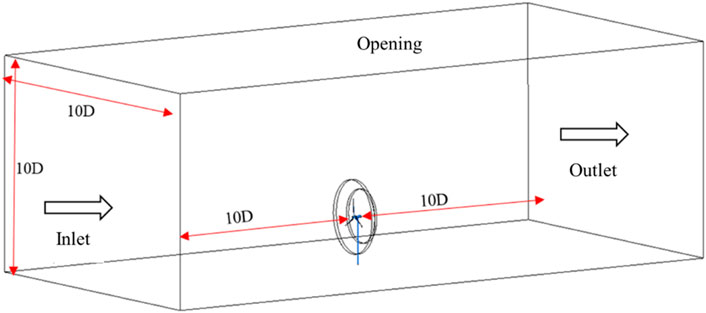
Figure 3. Computational domain and boundary conditions.
Convergence criterion: First, use the steady-state calculation method to calculate 10,000 steps. After the overall residual drops by more than four orders of magnitude and the convergence curve no longer drops with the number of iterations, switch to unsteady calculation. In the unsteady calculation, 40 steps are calculated within each physical time step. First, calculate 20 rotations in the unsteady state. After the monitored physical information is completely periodically convergent, it is considered that the calculation converges, and then calculate 10 rotations for time-averaged statistics.
Figure 4 shows the comparison between the CFD calculation results and the Design values. Bladed design values were obtained from high-fidelity aeroelastic simulations using DNV-Bladed 4.11 software (DNV, 2022), The dynamic stall model adopts the Beddoes Leishman model, and the dynamic wake model adopts the Pitt and Peters model (Leishman and Beddoes, 1989). The accuracy of Bladed for load prediction under similar conditions has been validated against field data in prior studies (Bangga and BladedFarmWake, 2002). It can be seen from the figure that the rotor shaft power obtained by CFD calculation is in good agreement with the Bladed design value before the rated wind speed of the rotor (3m/s-11 m/s). After the rated wind speed, due to power limitation, the research significance is not great, so CFD calculation is no longer carried out. It can be seen from Figure 4 that the single-rotor CFD numerical calculation method used in this report is feasible. The CFD results showed a maximum deviation of 4.2% from Bladed design values below the rated wind speed (3–11 m/s), confirming the validity of the numerical approach.
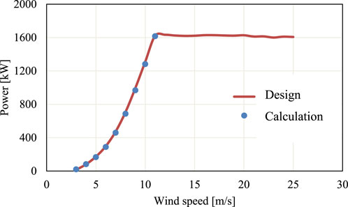
Figure 4. Comparison between CFD calculation results and Bladed design values.
Figure 5 shows the torque change law of the three blades of the rotor during 10 rotations. First, it can be seen from Figure 5 that the three blades fluctuate in a periodic alternating law. The low torque value is caused by the blade sweeping the tower, and the periodic sweeping of the three blades by the tower causes periodic fluctuations. Secondly, during the period when the blade does not sweep the tower, the blade torque value also fluctuates, indicating that there are periodic turbulent vortices causing it.
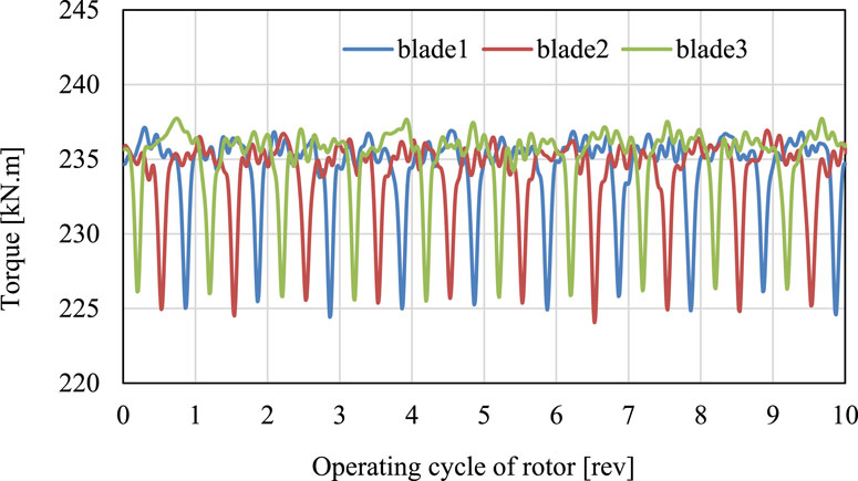
Figure 5. Torque change curve of blades during 10 rotations of the rotor.
Figure 6 shows the fluctuation of the three blades within one rotation period of the rotor. One blade can be divided into four regions within the range of one rotation of the rotor, namely, the 0°–90° region; 90°–180° region; 180°–270° region; 270°–360° region, corresponding to 0–0.25; 0.25–0.5; 0.5–0.75; 0.75–1.0 in the figure, four regions. The torque of the three blades fluctuates periodically.
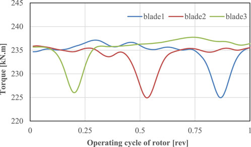
Figure 6. Torque change curve of blades within one rotation period of the rotor.
2.3 Dual-rotor numerical method validation
The large rotor has a diameter of 77 m, the small rotor has a diameter of 56 m, and the dual-rotor spacing is 20 m. The blade geometric model is shown in Figure 7.
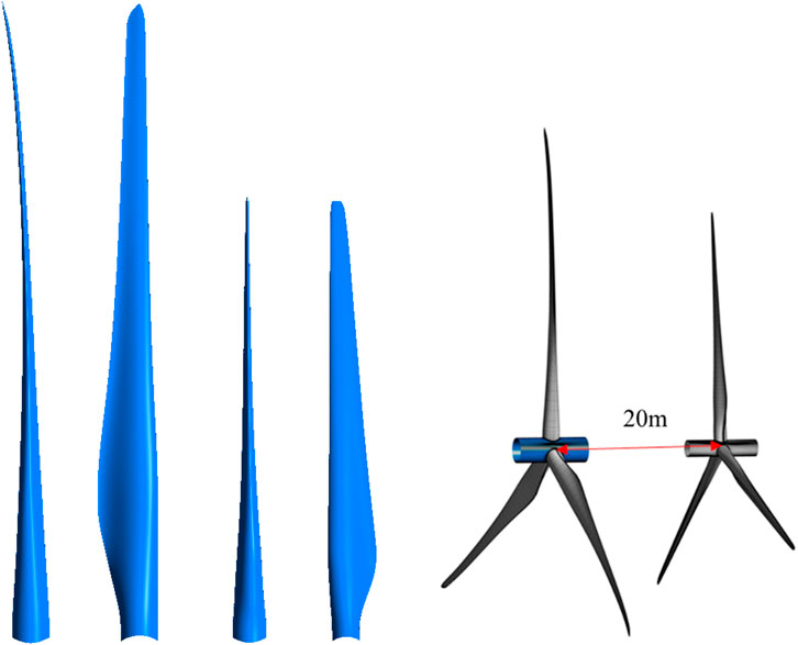
Figure 7. Large rotor diameter 77m, small rotor diameter 56m, rotor spacing 20 m.
Grid settings: Figure 8 shows the grid topology and grid distribution used for the dual-rotors in this calculation, and the method validation mainly studies grid convergence. Four sets of grids were set up, as shown in Table 2, with a total number of grids of 4.56 million, 9.52 million, 17.04 million, and 31.08 million respectively.
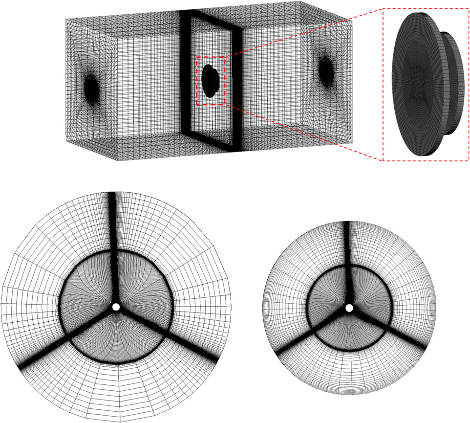
Figure 8. Flow field calculation grid for dual-rotors.
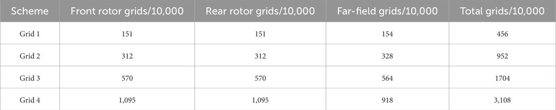
Table 2. Calculation of grid distribution.
Calculation settings: Figure 9 shows the boundary condition settings used in this calculation, using velocity inlet and pressure outlet, setting the blades as no-slip wall surfaces, and setting four cycles of the computational domain as open boundaries. The blade area is set as a sliding zone, the far field is a static domain, and the two rotors adopt a counter-rotating form, that is, the front rotor rotates clockwise and the rear rotor rotates counterclockwise.
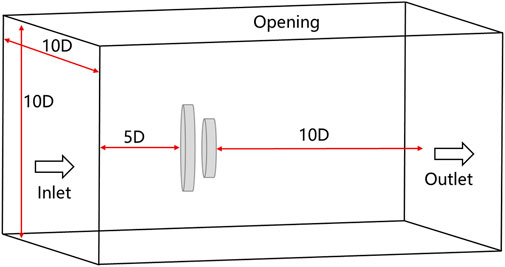
Figure 9. Calculation boundary condition settings.
Convergence criterion: First, use the steady-state calculation method to calculate 10,000 steps. After the overall residual drops by more than four orders of magnitude and the convergence curve no longer drops with the number of iterations, switch to unsteady calculation. In the unsteady calculation, 40 steps are calculated within each physical time step. First, calculate 20 rotations in the unsteady state. After the monitored physical information is completely periodically convergent, it is considered that the calculation converges, and then calculate 10 rotations for time-averaged statistics.
The calculation setting parameters are shown in Table 3.

Table 3. Calculation and setting parameters.
Result analysis: Table 4 shows the CFD calculation results of the four sets of grids, and Figure 10 shows the grid convergence curve of the dual-rotors. It can be seen from Table 4 and Figure 10 that the grid has a certain influence on the calculation results. As the number of grids increases, the dual-rotor Cp value gradually increases. When the total number of grids increases to 31.08 million, the calculation results have tended to be gentle, and it is preliminarily considered that the grid has convergence.
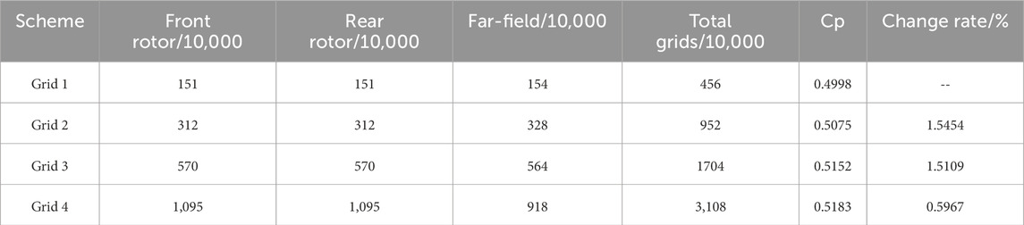
Table 4. CFD calculation results.
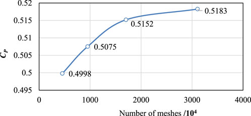
Figure 10. Grid convergence curve of dual-rotors.
V: Incoming wind speed.
3 Results analysis
Figure 11 shows the schematic diagram of dual-rotor arrangement, with the upstream being a large rotor and the downstream being a small rotor. The two rotors rotate in opposite directions, that is, the large rotor rotates clockwise and the small rotor rotates counterclockwise. By changing the spacing between the two rotors, the influence law of the spacing between the two rotors on the aerodynamic performance of the dual-rotors is explored. In the figure, D1 represents the diameter of the front wind turbine at 77 m, D2 represents the diameter of the rear wind turbine at 56 m, Speed1 represents the speed of the front wind turbine, and Speed2 represents the speed of the rear wind turbine. Table 5 shows the research scheme, where x in Table 5 represents the center spacing between the rotation planes of the front and rear rotors, D1 represents the diameter of the front rotor, and the spacing is made dimensionless. The aerodynamic characteristic changes of the dual-rotors under six groups of spacings are studied.
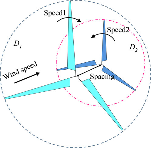
Figure 11. Schematic diagram of dual-rotor arrangement and working principle.
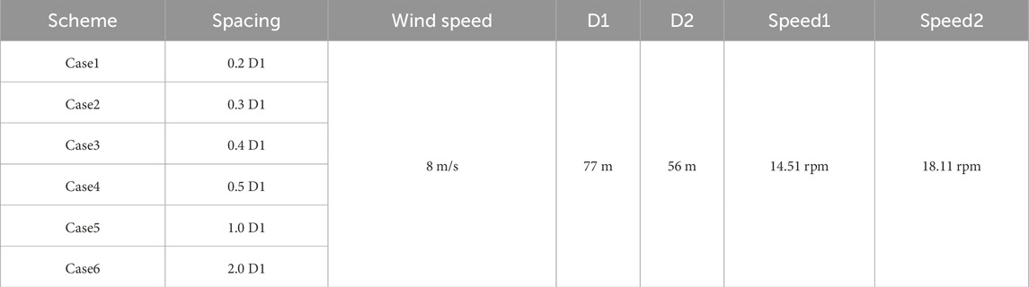
Table 5. Dual-rotor spacing parameter design table.
Figure 12 shows the change curve of dual-rotor aerodynamic characteristics with the increase of spacing. It can be seen from Figure 12 that as the spacing increases, the power of the front rotor gradually increases in a logarithmic growth law, and the power of the rear rotor gradually decreases with the increase of spacing. The power of the dual-rotors gradually increases with the increase of spacing, but before x is less than 0.5D, the increase slope is larger, and after 0.5D, the increase slope becomes gentle.
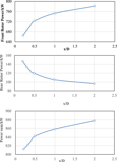
Figure 12. Influence law of dual-rotor spacing on rotor aerodynamic characteristics.
The results in Figure 12 show that the total power of the dual-rotors continues to increase with the increase of spacing (from 812.31 kW at 0.2D to 877.93 kW at 2.0D), but shows a segmented feature of “fast first, then slow”: in the interval from 0.2D to 0.5D, the total power growth rate is 30.3kW/D; in the interval from 0.5D to 2.0D, the growth rate drops to 15.6kW/D. This phenomenon is due to the change in the aerodynamic coupling effect between the front and rear rotors: at small spacings (≤0.5D), the rear rotor is in the strong shear wake area of the front rotor, and the blade surface angle of attack changes significantly due to velocity deficit and vorticity interference, leading to a rapid decrease in rear rotor power (from 146.97 kW at 0.2D to 119.66 kW at 0.5D), but the front rotor power increases rapidly due to the blockage effect of the rear rotor on the inflow; when the spacing exceeds 0.5D, the wake of the front rotor gradually enters the self-similar development stage, the velocity deficit and turbulence intensity of the rear rotor inflow tend to be stable, and the power change tends to be gentle.
Contrary to Shen et al. (Shen et al., 2007), who reported spacing-independent power for dual-rotors, our results demonstrate a logarithmic relationship (Figure 12). This discrepancy may stem from differences in rotor size ratios (front:rear = 77:56 m vs equal-size rotors in (Shen et al., 2007)), which amplify wake-blockage effects at small spacings.
Figure 13 shows the radial cross-sectional velocity cloud diagram and velocity distribution curve of the rotor. It can be seen that after the fluid passes around the rotor, the axial velocity of the fluid decreases rapidly, and the velocity gradually recovers only after 6D (534 m).
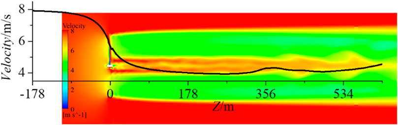
Figure 13. Flow field velocity cloud diagram and velocity change curve.
Figure 14 shows the velocity cloud diagram of the rotor section. Under different spacings, the change trend of the wake flow field inside the rotor is similar. As the spacing increases, the low-speed area of the rear rotor downstream wake becomes smaller and smaller.
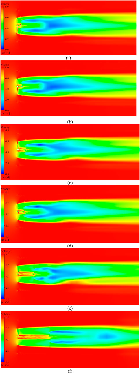
Figure 14. Velocity contours at rotor sections under different spacings: (a) 0.2D, (b) 0.3D, (c) 0.4D, (d) 0.5D, (e) 1.0D, (f) 2.0D. Color bars indicate axial velocity (m/s).
Figures 13, 14 show that the downstream axial velocity of the front rotor rapidly decreases to 6.0 m/s (inflow wind speed 8 m/s) within 1D and gradually recovers to 7.0 m/s after 6D. Under different spacings, the velocity distribution of the flow field where the rear rotor is located is significantly different; at 0.2D, the leading edge velocity of the rear rotor is only 5.5 m/s, and there is an obvious tip vortex-induced velocity deviation, leading to uneven blade loads; as the spacing increases to 2.0D, the inflow velocity of the rear rotor increases to 6.5 m/s, the velocity distribution is more uniform, and the influence of tip vortices weakens. Quantitative analysis revealed that the low-velocity region (axial velocity <6 m/s) occupied 38% of the rear rotor area at 0.2D, decreasing to 12% at 2.0D (Figure 14). This reduction correlates with enhanced wake recovery and reduced tip vortex intensity (Figure 13). The range of the wake low-speed area decreases with the increase of spacing, indicating that the wake mixing efficiency of the front and rear rotors is higher at large spacings, which is conducive to reducing energy loss.
At small spacings, the rear rotor bears stronger unsteady loads, which is related to the direct impact of the front rotor tip vortices on the rear rotor blades; when the spacing exceeds 1.0D, the tip vortex broken position moves backward, the turbulence intensity distribution tends to be stable, and the amplitude of rear rotor load fluctuations decreases. In addition, the Transition-SST model captures that at a spacing of 0.5D, the coupled vortex system formed between the two rotors significantly enhances the local turbulence dissipation, which provides a flow mechanism support for explaining the faster power growth rate at small spacings. Although total power continues to increase beyond 0.5D, the marginal gain (15.6 kW/D vs 30.3 kW/D) and escalating structural complexity justify prioritizing the 0.5D–1.0D range for practical designs.
It should be noted that wake interactions at large spacings (>5D) typical of wind farm layouts may exhibit different characteristics due to atmospheric turbulence and controller activation (Bangga et al., 2002). While this study focuses on compact dual-rotor systems (e.g., floating offshore applications), future work will extend to farm-scale spacing effects.”
4 Conclusion
Using the CFD method, the influence law of the spacing between the two rotors on the complex flow field and aerodynamic characteristics of the dual-rotors was studied. The main conclusions are as follows: The total power of the dual-rotors increases logarithmically with the increase of spacing, with 0.5D being the turning point of the power growth rate, and the total power increases by 8.1% compared with 0.2D; the spacing range of 0.5D–1.0D is recommended, where the aerodynamic coupling effect between the front and rear rotors is the most significant, and it is the key threshold for balancing efficiency and structural compactness in engineering design.
At small spacings, the strong blockage effect of the front rotor wake leads to a rapid decrease in rear rotor power, but the front rotor obtains additional gains due to the suction effect of the rear rotor; at large spacings, the wake velocity recovers more fully, turbulence mixing is enhanced, and the total power continues to increase but the growth rate slows down.
This study clarifies the influence law of spacing on the flow field structure and load characteristics, provides a “efficiency-load” dual-objective design basis for the spacing optimization of dual-rotor turbines, and suggests that the spacing range of 0.5D to 1.0D should be preferentially considered in practical engineering to balance energy capture and structural stability.
Future research can further verify the simulation results combined with wind tunnel tests, explore the influence of parameters such as variable pitch and different diameter ratios on the spacing effect, and lay a more solid theoretical foundation for the engineering application of tandem dual-rotors. Future research will integrate aeroelastic analysis using coupled CFD-BEM methods to assess fatigue loads and instability risks, particularly for floating platform applications where dynamic amplification may occur.”
Dual-rotor wind turbine have the advantages of high efficiency and small wind turbine radius. Under the same sweeping area, dual wind turbine units are more efficient and generate more electricity than single wind turbine units. With the same power generation, the wind turbine radius is smaller, making transportation and lifting easier. Based on this characteristic, dual turbine wind turbines are more suitable for offshore floating wind power and onshore complex terrain wind farms.
Data availability statement
The original contributions presented in the study are included in the article/supplementary material, further inquiries can be directed to the corresponding author.
Author contributions
XL: Conceptualization, Writing – review and editing, Writing – original draft. XG: Conceptualization, Investigation, Writing – original draft. CL: Software, Formal Analysis, Writing – original draft. ZY: Writing – original draft, Validation, Methodology, Software. XS: Writing – original draft, Formal Analysis.
Funding
The author(s) declare that financial support was received for the research and/or publication of this article. The authors are sincerely grateful for the financial support from China Huaneng Group Science and Technology Project (No. HNKJ24-H16). We are also indebted to anonymous reviewers for their perceptive comments and valuable suggestions for enhancing this paper.
Acknowledgments
The authors thank the editors and reviewers for their comments on this paper.
Conflict of interest
The authors declare that the research was conducted in the absence of any commercial or financial relationships that could be construed as a potential conflict of interest.
Generative AI statement
The author(s) declare that no Generative AI was used in the creation of this manuscript.
Publisher’s note
All claims expressed in this article are solely those of the authors and do not necessarily represent those of their affiliated organizations, or those of the publisher, the editors and the reviewers. Any product that may be evaluated in this article, or claim that may be made by its manufacturer, is not guaranteed or endorsed by the publisher.
References
Agrawal, V. V. (2010). Design and aero-acoustic analysis of a counter-rotating wind turbine. Ann Arbor: Purdue University.
Ai, K., Cui, J., Wang, M., and Avital, E. (2020). Numerical modelling of a dual-rotor marine current turbine in a rectilinear tidal flow. Ocean. Eng. 200, 107026. doi:10.1016/j.oceaneng.2020.107026
Appa, K. (2002). EISG final report - counter rotating wind turbine system. Lake Forest, CA: Appa Technology Initiatives.
Bangga, G., and BladedFarmWake, E. B. (2002). A framework for evaluating the influence of upstream wakes on turbine loads using Bladed. J. Phys. Conf. Ser. 2767.
Bangga, G., Parkinson, S., and Lutz, T. (2002). Utilizing high fidelity data into engineering model calculations for accurate wind turbine performance and load assessments under design load cases. IET Renew. Power Gener. 16 (10), 1983–1995.
Cho, W., Lee, K., Choy, I., and Back, J. (2017). Development and experimental verification of counter-rotating dual rotor/dual generator wind turbine: generating, yawing and furling. Renew. Energy 114, 644–654. doi:10.1016/j.renene.2017.06.083
Gregg, J. R., Merchant, J. S., and Van Treuren, K. W. (2009). Experimental analysis of a counter-rotating wind turbine: ASME 2009 international mechanical engineering congress and exposition. Florida, USA: Lake Buena Vista.
Habash, R. W. Y., Groza, V., Yang, Y., Blouin, C., and Guillemette, P. (2011). Performance of a contrarotating small wind energy converter. ISRN Mech. Eng. 2011, 1–10. doi:10.5402/2011/828739
IRENA. Renewable Technology Innovation Indicators: Mapping progress in costs (2022). Abu Dhabi, 84–135.Int. Renew. Energy Agency
Kanemoto, T., and Galal, A. M. (2006). Development of intelligent wind turbine generator with tandem wind rotors and double rotational armatures (1st report, superior operation of tandem wind rotors). JSME Int. J. Ser. B 49 (2), 450–457. doi:10.1299/jsmeb.49.450
KMUTT Sustainable Development (2008). Axial momentum theory for turbines with Co-axial counter rotating rotors: commemorative international conference of the occasion of the 4th cycle anniversary of KMUTT sustainable development to save the earth: technologies and strategies vision 2050. Thailand: Bangkok.
Kubo, K., and Kanemoto, T. (2008). Development of intelligent wind turbine unit with tandem wind rotors and double rotational armatures (2nd report, characteristics of tandem wind rotors). J. Fluid Sci. Technol. 3 (3), 370–378. doi:10.1299/jfst.3.370
Kumar, P., Abraham, A., and Bensingh, R. (2013). Computational and experimental analysis of a counter-rotating wind turbine system. J. Sci. Industrial Res. 72, 300–306.
Lee, S., Kim, H., and Lee, S. (2010). Analysis of aerodynamic characteristics on a counter-rotating wind turbine. Curr. Appl. Phys. 10 (2), S339–S342. doi:10.1016/j.cap.2009.11.073
Lee, S., Son, E., and Lee, S. (2013). Velocity interference in the rear rotor of a counter-rotating wind turbine. Renew. Energy 54, 235–240. doi:10.1016/j.renene.2012.08.003
Leishman, J. G., and Beddoes, T. S. (1989). A semi-empirical model for dynamic stall. J. Am. Helicopter Soc. 34 (3), 3–17. doi:10.4050/jahs.34.3.3
Lipian, M., Dobrev, I., Karczewski, M., Massouh, F., and Jozwik, K. (2019). Small wind turbine augmentation: experimental investigations of shrouded- and twin-rotor wind turbine systems. Energy 186, 115855. doi:10.1016/j.energy.2019.115855
Li, Z., Wang, Y., and Xiao, H. (2013). “Experimental study on structures of counter-rotating wind turbines,” in 2013 international conference on materials for renewable energy and environment. Chengdu, China: IEEE.
Li, Z., Wang, Y., and Zhang, Y. (2011). “Experimental study on interaction of the counter-rotating rotors in a wind turbine,” in 2011 international conference on materials for renewable energy and environment. Shanghai: IEEE.
Li, Z., Wu, Y., Hong, J., Zhihong, Z., and Wenqi, C. (2018). The study on performance and aerodynamics of micro counter-rotating HAWT. Energy 161, 939–954. doi:10.1016/j.energy.2018.07.049
Lu, Ma, Li, Y., and Zhou, Le (2025). Study on the aeroelastic performance of 15 MW wind turbine under yaw condition. Front. Energy Res. 3, 24.
Mitulet, L., Oprina, G., Chihaia, R., Nicolaie, S., Nedelcu, A., and Popescu, M. (2015). Wind tunnel testing for a new experimental model of counter-rotating wind turbine. Procedia Eng. 100, 1141–1149. doi:10.1016/j.proeng.2015.01.477
Moghadassian, B., Rosenberg, A., and Sharma, A. (2016). Numerical investigation of aerodynamic performance and loads of a novel dual rotor wind turbine. Energies 9 (7), 571. doi:10.3390/en9070571
Mohamed, A., EL-Baz, A., and Mahmoud, N. (2019). CFD simulation of ducted dual rotor wind turbine for small-scale applications: ASME 2019 gas turbine India conference, Chennai, Tamil nadu, India. American Society of Mechanical Engineers.
Newman, B. G. (1983). Actuator-disc theory for vertical-axis wind turbines. J. Wind Eng. Industrial Aerodynamics 15 (1), 347–355. doi:10.1016/b978-0-444-42342-9.50046-0
Newman, B. G. (1986). Multiple actuator-disc theory for wind turbines. J. Wind Eng. Industrial Aerodynamics 24 (3), 215–225. doi:10.1016/0167-6105(86)90023-1
Ozbay, A., Tian, W., and Hu, H. (2014). “A comparative study of the wake characteristics behind a single-rotor wind turbine and dual-rotor wind turbines,” in 32nd AIAA applied aerodynamics conference. Atlanta, GA.
Ozbay, A., Tian, W., and Hu, H. (2015). “An experimental investigation on the wake characteristics and aeromechanics of dual-rotor wind turbines: ASME turbo expo,” in Turbine technical conference and exposition. Montreal, CANADA: American Society of Mechanical Engineers.
Porté- Agel, F., Bastankhah, M., and Shamsoddin, S. (2020). Wind-turbine and wind-farm flows: a review. Boundary-Layer Meteorol. 174 (1), 1–59. doi:10.1007/s10546-019-00473-0
Rosenberg, A., Selvaraj, S., and Sharma, A. (2014). A novel dual-rotor turbine for increased wind energy capture. J. Phys. Conf. Ser. 524, 012078. doi:10.1088/1742-6596/524/1/012078
Shen, W. Z., Zakkam, V. A. K., and Sø Rensen, J. N. (2007). Analysis of counter-rotating wind turbines. J. Phys. Conf. Ser. 75, 12003.
Slew, K. L., Miller, M., and Matida, E. (2016). A numerical investigation to identify dimensionless parameters for dual-rotor horizontal Axis wind turbines. J. Phys. Conf. Ser. 753, 102006. doi:10.1088/1742-6596/753/10/102006
Sø Rensen, J. N. (2011). Aerodynamic aspects of wind energy conversion. Annu. Rev. fluid Mech. 43 (1), 427–448. doi:10.1146/annurev-fluid-122109-160801
Sun, Y., and Jianfeng, T. (2019). Zhou Tianyi the influence of rotor spacing and phase angle on the power characteristics of dual rotor wind turbines. J. Power Eng. 39 (10), 853–859.
Sundararaju, H., Lo, K. H., Metcalfe, R., and Wang, S. S. (2017). Aerodynamics and CFD analysis of equal size dual-rotor wind turbine. J. Renew. Sustain. Energy 9 (4), 43305. doi:10.1063/1.4999500
Ushiyama, I., Shimota, T., and Miura, Y. (1996). An experimental study of the two-staged wind turbines. Renew. energy 9 (1), 909–912. doi:10.1016/0960-1481(96)88427-8
Vasel-Be-Hagh, A., and Archer, C. L. (2017). Wind farms with counter-rotating wind turbines. Sustain. Energy Technol. Assessments 24, 19–30. doi:10.1016/j.seta.2016.10.004
Veers, P. S., Ashwill, T. D., Sutherland, H. J., Laird, D. L., Lobitz, D. W., Griffin, D. A., et al. (2003). Trends in the design, manufacture and evaluation of wind turbine blades. Wind Energy 6 (3), 245–259. doi:10.1002/we.90
Wang, Z., Ozbay, A., Tian, W., and Hu, H. (2018). An experimental study on the aerodynamic performances and wake characteristics of an innovative dual-rotor wind turbine. Energy 147, 94–109. doi:10.1016/j.energy.2018.01.020
Wei, X., Huang, B., Kanemoto, T., and Wang, L. (2017). Near wake study of counter-rotating horizontal axis tidal turbines based on PIV measurements in a wind tunnel. J. Mar. Sci. Technol. 22 (1), 11–24. doi:10.1007/s00773-016-0389-7
Yuan, W., Ozbay, A., and Tian, W. (2013). An experimental investigation on the effects of turbine rotation directions on the wake interference of wind turbines: 51st AIAA aerospace sciences meeting including the new horizons forum and aerospace exposition, grapevine (Dallas/Ft. Worth region). Texas: American Institute of Aeronautics and Astronautics.
Yuan, W., Tian, W., Ozbay, A., and Hu, H. (2014). An experimental study on the effects of relative rotation direction on the wake interferences among tandem wind turbines. Sci. China Phys. Mech. & Astronomy 57 (5), 935–949. doi:10.1007/s11433-014-5429-x
Keywords: dual-rotor, wind turbine, CFD, Spacing, flow field
Citation: Li X, Guo X, Liao C, Ye Z and Shen X (2025) Investigation of flow field characteristics around a novel high-efficiency tandem dual-rotor wind turbine under different rotor spacings. Front. Energy Res. 13:1616716. doi: 10.3389/fenrg.2025.1616716
Received: 23 April 2025; Accepted: 09 June 2025;
Published: 28 July 2025.
Edited by:
Galih Bangga, DNV GL, United KingdomReviewed by:
Yang Yang, Ningbo University, ChinaJian Chen, University of Shanghai for Science and Technology, China
Copyright © 2025 Li, Guo, Liao, Ye,and Shen. This is an open-access article distributed under the terms of the Creative Commons Attribution License (CC BY). The use, distribution or reproduction in other forums is permitted, provided the original author(s) and the copyright owner(s) are credited and that the original publication in this journal is cited, in accordance with accepted academic practice. No use, distribution or reproduction is permitted which does not comply with these terms.
*Correspondence: Xinkai Li, eGtfbGkyQHFueS5jaG5nLmNvbS5jbg==