 Ole Jorgen Nydal1*
 Peter Mashingo2†Gunn Helen Nylund1Andreas Bjørshol1Alexander Peter Olsen1
 Jimmy Chaciga3
- 1Department of Energy and Process Engineering, Norwegian University of Science and Technology, Trondheim, Norway
- 2Arusha Technical College, Arusha, Tanzania
- 3Department of Physics, Makerere University, Kampala, Uganda
Energy storage solutions are required for renewable energy systems to provide energy on demand, independently of the time fluctuations of the sources. Electrical batteries provide electrical power, and thermal batteries can likewise provide heating and cooling power directly. An electrical battery can give power at a rated voltage for a partially charged battery as well as for a fully charged battery, and a similar feature would be useful in the case of a thermal battery. In a thermal energy storage system, temperature is a measure of the quality of the energy, and the energy should preferably be available at high temperatures for both partially and fully charged storages. This is the case for latent heat storage systems, as long as the system is in the two-phase region. A similar feature can be achieved in liquid-based sensible heat storage systems where the heat transfer is carried out by the flow of a heat transfer fluid into and out of the storage. If the storage is designed to prevent thermal mixing, either by physical separation of hot and cold fluid in separate containers or by natural thermal stratification in a single container with hot fluid on top of cold fluid, the thermal energy can be extracted at nearly the same temperature as the charging temperature. Then, a temperature control method is needed to feed the storage with a high-temperature stream, independent of the charging power. In this study, we examine a passive thermal regulation approach in a heat storage system designed for cooking applications, utilizing internal natural oil circulation to manage heat distribution and maintain consistent operating temperatures. An expansion-based temperature control method is presented, where the expansion of the heat transfer fluid itself is used as the basis for controlling the charging temperature of an oil-based heat storage unit. A heating element provides the charging power. The oil is heated in a heating chamber that includes a barrier for the circulation of the oil with the storage unit. At a given temperature, the oil expands beyond the barrier, and circulation with the storage unit is initiated. The performance of the method is demonstrated using a set of dedicated experiments, and the method is furthermore applied to heat storage systems for cooking. A strong motivation for the work is to find robust and simple solutions for clean cooking technology in the African environment.
1 Introduction
The development of technologically simple heat storage solutions for cooking has been the main motivation for the work described here. The aim is to accumulate thermal energy in a heat storage that can be charged with intermittent power from photovoltaic (PV) panels and/or wind generators to provide high-temperature thermal energy for cooking when needed. The work described here demonstrates the particular performance of a method for regulating the temperature in an oil-based heat storage solution with natural internal circulation, based on the expansion of the oil with temperature alone.
The need for clean cooking technology has been on the agenda for quite some time in countries where wood fuel remains the dominant energy source for cooking, particularly due to the serious health and environmental concerns associated with wood-based open-fire cooking practices.
Several overviews of direct cooker technologies are available; some of the more recent overviews are provided by Arunachala and Kundapur (2020) and Cuce and Cuce (2013). Inclusion of heat storage features in solar cookers can facilitate off-sun cooking. A general discussion on requirements and concepts for heat storage for cooking is provided by Nydal (2023). Some reviews on heat storage methods for cookers are provided by Sharma et al. (2009), Lentswe and Mawire (2021), and Aramesh et al. (2019).
The background concept for the present work is a sensible heat storage system, in which oil serves as both the storage medium and the heat transfer fluid for the cooker. Such a system can exhibit some attractive properties if the heated oil can be separated from the cold oil in the heat reservoir, thereby reducing the degradation of the exergy by thermal mixing. Separation of the hot and cold oil can be achieved using separate tanks or by thermal stratification in a single storage tank. These systems are then open for regulation of both the storage temperature (the hot oil part) and the power to the cooker (the flow rate of hot oil to the cooker).
One effective method for regulating temperature is using thermostats, which provide precise control by monitoring and adjusting the system based on set temperature thresholds. Thermostats are commonly used for the regulation of temperatures in a wide variety of processes or systems, for example, space heating and cooling (the building environment), hot water systems (domestic and industrial), ovens and refrigeration systems (home appliances), conservation systems (agriculture and medicine), protection for freezing and overheating (industries and transport sector), and probably many more. A thermal control system includes a thermal sensor that is used to drive an action, such as a mechanical actuator or an electrical switch. The technology has developed from fully mechanical systems (thermal sensor and actuator combined) to digital systems that are more readily open for advanced control schemes (Tamas et al., 2021). Mechanical systems exploit the thermal expansion of different substances (wax, bimetal strips or coils, and gas bulbs). Digital systems process signals from temperature sensors (thermocouples and thermistors) to control the heating or cooling systems. Detailed information on concepts, products, and guides is available on the web sites of several suppliers.
The aim of the current work is to develop systems that are both simple and robust, particularly in response to the specified requirements for off-grid applications without using electrical batteries, thermostat valves, and pumps. The systems should also be suitable for local production and maintenance, be safe to operate, and not pose any threats to the environment.
These requirements would exclude common sensor–actuator systems, and the concept for testing here relies on natural circulation and temperature regulation based directly on the expansion properties of the oil. The viscosity and the thermal volumetric expansion are the two oil properties of particular importance.
Several research workers have considered edible oils as alternative candidates for heat transfer oils instead of synthetic thermal oils. Hoffmann et al. (2018) measured the properties of seven vegetable oils. Mahavar et al. (2025) examined the use of sunflower oil for heat transfer and storage applications and also reviewed several other edible oils. The review provided by Gomna et al. (2019) included considerations of the thermal and mechanical properties of the oils, as well as the degradation by oxidation. The need for long-term degradation evaluations was also noted by N’Tsoukpoe et al. (2021), who conducted a detailed comparison of nonedible Jatropha oil with two synthetic thermal oils for use in solar thermal power plants. The viscosities of edible oils are normally higher than those of mineral oils, but viscosities become even higher after long-term exposure to air. Viscosity measurements of three edible oil samples (sunflower, olive, and rapeseed oil) and one thermal oil sample (Duratherm 630) revealed that the edible oils were unstable to oxidation after 1 year of exposure to ambient air (Kahsay and Nydal, 2023). The viscosity increased by approximately 100 times for rapeseed oil and 10 times for olive oil after 1 year, and sunflower oil turned into a sticky solid. The Duratherm thermal oil preserved the properties during aging, but thermal degradation as a result of thermal cycling still needs to be assessed.
In addition to viscosity, thermal expansion characteristics are also critical for evaluating the suitability of oils in thermal systems. The coefficient of volumetric expansion is not noted as a property of particular concern for thermal oils in previous studies. The data sheets of thermal oils, however, indicate similar values for the coefficient of relative expansion, with typical values varying from 0.07
Based on previous research, Duratherm 630 thermal oil is selected in this study for heat transfer and storage applications in the development of oil-based solar cookers.
Four different experimental setups have been constructed and tested for natural circulation with expansion-based temperature control:
• A once-through system for testing the temperature control of a heated oil stream based only on the expansion of the oil.
•A closed-flow U-tube system with natural circulation.
•A tank with an integrated heater and cooker and internal circulation for charging and discharging of the heat storage.
•A similar solution but with the heater and the cooker external to the storage tank.
The principles for the thermal control in the self-circulating systems are described both conceptually and in terms of a simplified computational model implemented in MATLAB. The four setups are described, and the test results are presented for each case. The performance of the expansion-based control system is evaluated, and the differences between the systems are discussed.
2 Methods
A step-wise approach has been adopted to test the expansion-based thermal control in self-circulating systems, beginning with simple setups for the proof of concept and moving to solutions that include cooker units.
2.1 Principle
The principle of the expansion-based method for thermal control in a self-circulating system is shown in Figure 1.
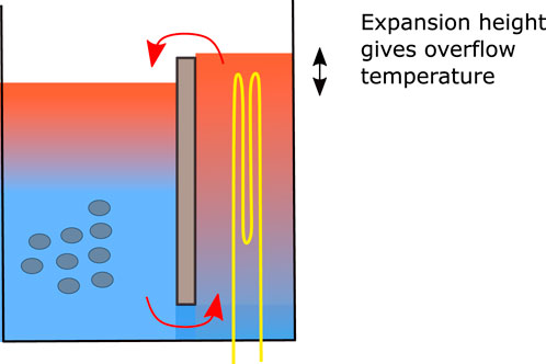
Figure 1. Principle of the expansion-based passive temperature control of thermal oil, with a heating chamber connected to a heat storage chamber.
Two chambers with oil are connected at the bottom and top ends. The chambers can either be separated with a barrier, as shown in Figure 1, or be in the form of separate containers connected to upper and lower pipes. Starting from uniform temperatures in the left and right parts, the bottom left and right pressures are equal and correspond to the static head of the oil layers (Equation 1).
where
As heating in the right chamber continues, circulation ideally continues, with a sharp downward-moving thermal front in the left heat storage chamber. In reality, thermal conduction will provide a decay of the thermal front over time (the thermocline). With continued heating, the level on the storage side will also increase, and after the barrier height is reached, both the levels on the left-hand and right-hand sides continue to increase above the barrier. The circulation is now determined by the level gradient of the oil surface.
If the pressures are close to gravitational pressures (near-static conditions), then the overflow temperature will be conserved and remain at similar values until the thermal front reaches the bottom of the heat storage side. At this point, the temperature of the oil entering into the heater begins to increase. The heating is no longer from the initially cold oil but from increasingly hot oil coming from the storage side at the bottom. From this point on, the overflow temperature continues increasing, and the system is approaching a fully charged state, at which the heating power must eventually be stopped to avoid overheating of the oil.
Heat extraction from a hot storage to the cooker is based on the same principle of natural circulation. Now, the oil temperature in the heating side (the cooking side) will decrease as heat is transferred to the cooker, and the resulting reduction in the oil level in the cooker side will induce the opposite circulation compared with the charging case.
Given a sharp thermocline on the storage side, it indicates that heat can be provided from the storage side to the cooker at temperatures similar to the charging temperature, even in the case of a partially heated thermal storage. The storage can then act as a buffer, absorbing excess heat when power is available on the heating element and delivering the stored heat back to the cooker, when the power is unavailable, both through natural circulation. Fluid mixing in the storage side would destroy this property, and useful energy from the storage would only be available after the storage has been sufficiently charged.
2.2 A simplified computational model
2.2.1 The effect of area change
The concept is based on near-flow equilibrium, where the pressures at the bottom of each chamber are mainly the static head, and not influenced by fluid acceleration. If the left and right pressures
If the relative height increase during heating is greater than the relative density decrease, then
where
2.2.2 Simplified computational model
Thermal oils can expand quite significantly, with relative expansion coefficients typically approximately
where
where
The rate of circulation is determined according to a balance between the driving gravity forces and the retarding friction forces, assuming negligible acceleration effects. The oil experiences flow resistance due to integrated internal friction along all surfaces of the flow path, including the container walls, connecting pipes, and, in cases where the storage part consists of oil in a rock bed, the surfaces of the rock pebbles.
The integrated pressure from the surface on the right side to the left side (same surface pressures) provides a balance between the gravitational and frictional parts under quasi-steady-state conditions, as presented in Equation 7:
where
where
Equations 7, 8 then yield the velocity, which is also used in the dynamic case, assuming slow changes in time. The circulation flow rate
The pressure response depends on the change in the oil density as well as the level change, and the level change is affected by diameter changes, as shown in Equation 3. A reduction in the diameter of the heater can initially cause adverse behavior with reverse flow, as the expansion in the hot chamber now occurs over a smaller diameter.
The flow rate
The 1D mass balance is presented in Equation 10:
where
where M is the total mass in each chamber, left (L) and right (R). A 1D energy balance yields the time evolution of the temperatures along the flow path, as shown in Equation 12:
where
A discretized version of the simplified model scheme above has been used for the evaluation of dynamic scenarios of charging with a heat source
The set of equations is solved sequentially and non-iteratively with an explicit time integration, which is stable provided that sufficiently small time steps are used. Numerical energy conservation is ensured by integrating
• Densities from the state equation, Equation 6
• Level heights from the integration of the masses with new densities, Equation 10
• Mass flow
• Mass flow
• Masses from new flow rates, Equation 10
• Energies from the energy balance, Equation 12
• Temperatures from the new energies and masses, Equation 13
The thermal loss coefficient was tuned to provide similar temperature decreases of the oil as in the experiments (
3 Demonstration of the temperature regulation concept using the once-through system
3.1 Materials and methods
A simple first demonstration of the concept of the expansion-based temperature control is shown in Figure 2, and the characteristics of the setup are listed in Table 1. The once-through system was constructed with a large oil reservoir coupled with a tube to a small heating chamber having a 12V, 150W heating element inside. Figure 2b shows the setup before insulation of the heater section.
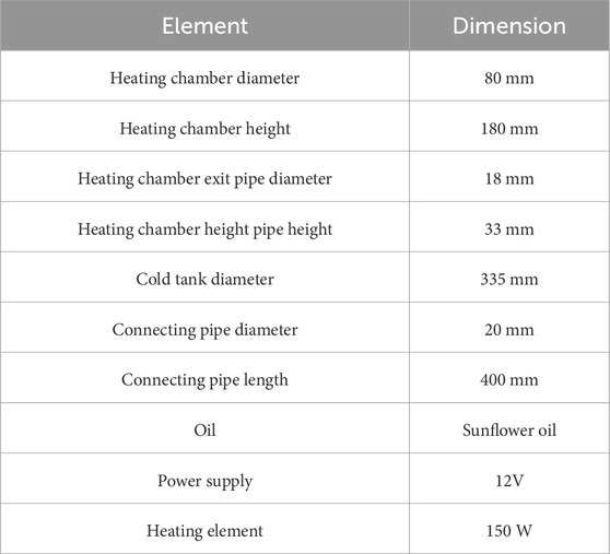
Table 1. Characteristics of the setup for the once-through tests in Figure 2.
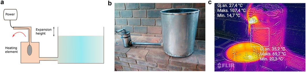
Figure 2. Once-through system for testing of expansion based temperature control. (a) Principle of once-through test for expansion-based temperature control. (b) System for once-through test for expansion-based temperaturecontrol before insulation. (c) Thermal picture during experiment with once-through test forexpansion-based temperature control.
The heater has a reduced diameter at the outlet tube, and some initial reverse flow was noted after initiation of heating. As the storage tank was much larger than the heating chamber, the effects of the initial reversed flow were small. The results of the experiments are reflected in the following section.
3.2 Results
Figure 3 shows temperature recordings in an experiment together with computations.
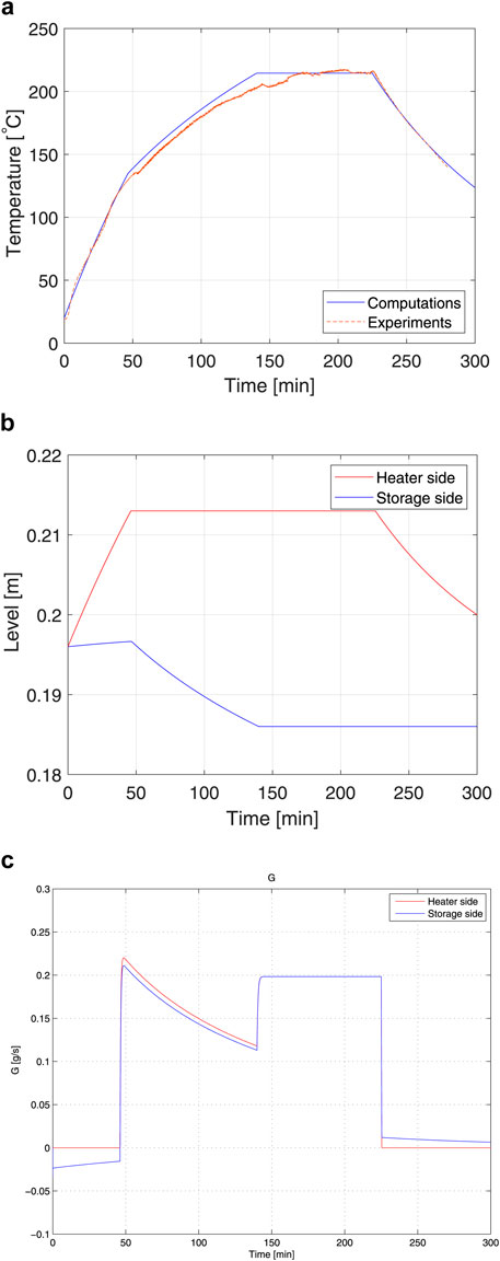
Figure 3. Experiments and computations on the once-through system. (a) Measurements and computational results for the once-through test on the temperature control concept. At approximately 140 min, thehot oil is circulated from the outlet back to the storage, and at approximately 225 min, the power is shut off. (b) Computational results for the oil levels in the heater (red) and in thestorage tank (blue) for the once-through test on temperature control.At approximately 140 min, the hot oil is circulated from the outlet backto the storage. (c) Computational results for the oil flow rates out of the heater (red) andin the connection tube (blue) for the once-through test ontemperature control. At approximately 140 min, the hot oil iscirculated from the outlet back to the storage.
When power is switched on, the oil temperature in the heater section increases, and the oil expands accordingly. After approximately 40 min, overflow occurs and the further temperature increase becomes slower due to the also decreasing level in the storage side. At approximately 140 min, the hot oil coming out of the heater section was collected and inserted back into the cold tank. From this point in time, the temperature out of the heater stabilizes as the level in the hot tank is now stable.
The plots from the computations using the simplified model described above also illustrate the physics of the process. Figure 3b shows the levels in the hot chamber (red) and in the cold container (blue), and Figure 3c shows the flow rates in the connecting tube (blue) and out of the hot chamber (red). The outlet pipe diameter is smaller than the heating chamber diameter, which leads to an initial negative flow behavior. Oil flows from the heater to the cold container, and the level in the cold container increases. This reverses after the expanding oil in the heating chamber reaches the overflow level and oil flows out of the hot chamber. The subsequent outlet temperatures will increase further because the level in the cold tank decreases, requiring a higher oil temperature to reach the overflow level. After approximately 240 min, the power is shut off, and the oil outflow stops. The level in the heater decreases as the oil cools down, which also results in a small positive flow from the cold side.
4 Demonstration of temperature control in a closed-flow system
4.1 Materials and methods
A second setup was constructed to test a closed system, in which the overflow of hot oil enters back into the storage side. This was arranged with a U-shaped pipe geometry, as shown in Figure 4. The top part of the U-tube was joined, and three heating elements (150 W each, 12V) were combined in a vertical string on the heater side.
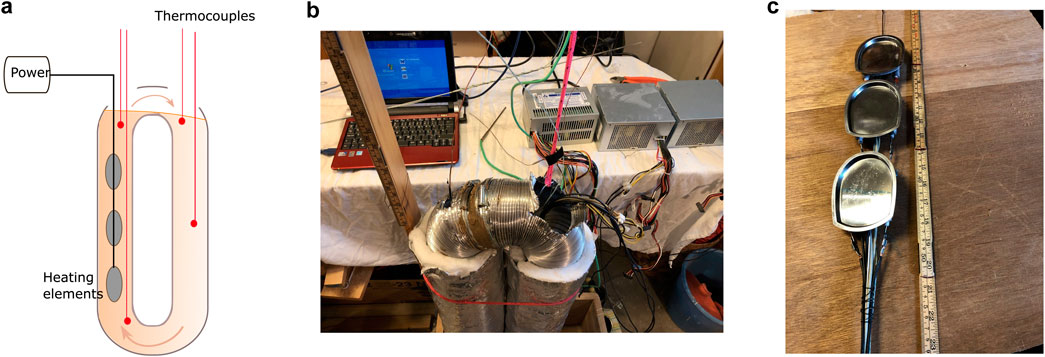
Figure 4. Setup of closed-loop system. (a) Schematic diagram of the setup for a closed-circulation system in aU-tube geometry. (b) Setup for the closed-circulation system. (c) Heating elements applied in the closed-circulation system.
The thermal stratification was measured by lowering a thermocouple attached to a very thin steel rod (welding wire). The rod was lowered in steps of 1 cm every 5 s, first downward and then upward again. By inspecting the temperature recordings, it was observed that 5 seconds was sufficient time for the thermocouple to reach new steady recordings after each elevation change. However, this process takes some time to scan the temperatures from the top level to the bottom of the U-tube (approximately 5 min), which suggests that the temperature profile may be somewhat inaccurate in cases where the front propagates significantly during the traversal. The current experiments were carried out with a low-power system, resulting in slow temperature changes; the time span of the heating period was approximately 300 min. The results of the experiments are provided in the following section.
4.2 Results
The initial oil level was below the joining part of the U-tube, and Figure 5a shows the temperature evolutions in the top part on both sides after three heating elements were switched on. The temperature at the top of the heater side increases rapidly until the oil level reaches the top and the overflow to the storage side begins.
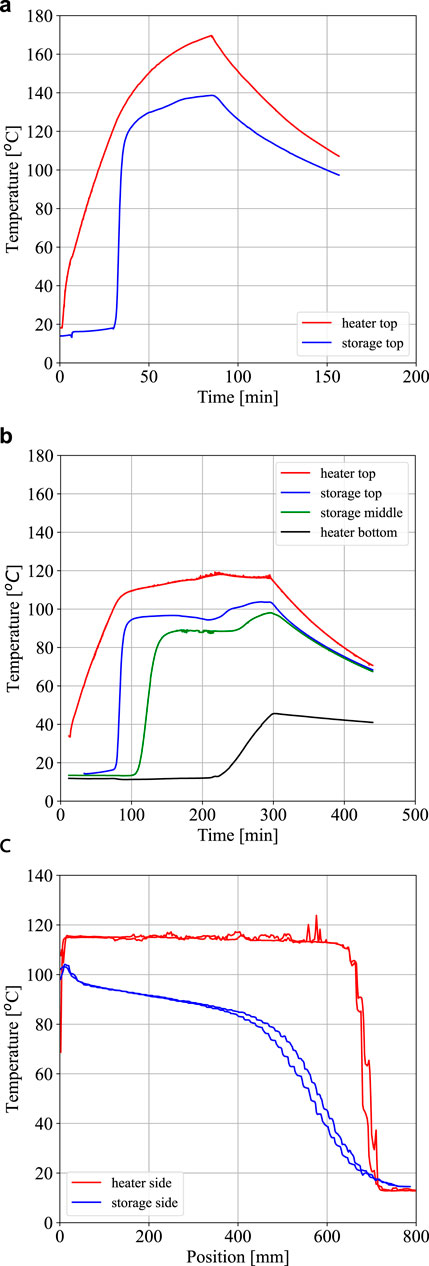
Figure 5. Experiments with the closed-loop system of Figure 4. (a) Experiments with the closed-loop system of Figure 4. High power case (three heating elements). (b) Experiments with the closed-loop system of Figure 4. Low power case (one heating element). (c) Experiments with the closed-loop system of Figure 4. Temperatureprofiles from up and down traverses with a thermocouple atapproximately 150 min. Hot side (red) and cold side (blue).
After overflow occurs, the storage side temperature does not reach the same values as the hot side, presumably due to thermal losses at the top of the U-tube, which was poorly insulated, due to mixing in the top layer on the storage side and a somewhat lower position of the thermocouple compared to the hot side. The hot side temperature in this case is observed to keep increasing also after overflow begins. This shows that if the power supply is large in relation to the heating volumes, the flow rate may not keep up to be near the equilibrium conditions. Figure 5b shows that the case with power supplied only to the lowest heating element at the bottom of the hot side produced results closer to the aim of maintaining constant exit temperatures after overflow. The circulation rate is now less than the case with three heating elements, and the temperatures increase more slowly. As the thermal front reaches the bottom part of the U-tube, the bottom temperature sensor in the hot side begins to increase. The resulting temperature profiles at approximately 150 min are shown in Figure 5c. The hot side with a heating element at the bottom has uniform temperature, whereas the cold side shows some spread in the thermocline. The upward traverse measurement follows after the downward traverse and therefore also shows some propagation of the front.
The simple case in the circulation tests showed that the concept of expansion-based temperature control is feasible but has limitations regarding the power levels that the circulation can sustain at a flow rate close to the steady state.
5 Methods for temperature control
The expansion-based temperature control was applied to two cases of heat storage units designed for cooking applications. The concept falls within the same concept by using an oil-based sensible heat storage that exchanges energy with a cooker through natural circulation. This setup is similar to the U-tube case, where a cooker is now positioned on the top part of the heater side.
Two concepts have been explored. In the first concept, the cooker on top of a funnel with the heating element is placed inside the storage tank. In the other, the cooker with the heating elements is placed outside the storage tank and connected by pipes at the top and bottom (see the diagrams in Figure 6 and in Figure 10 further below).
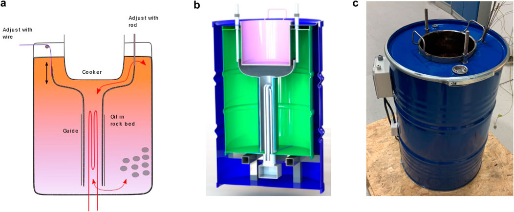
Figure 6. System with an internal cooker and regulation by flow barrier movement. (a) System with an internal cooker and two mechanical methods forregulation of the flow barrier. (b) Drawing of the system with an internal cooker. Barrel-in-barrelsolution with insulation in between. (c) Barrel-in-barrel system with an internal cooker.
The height of the barrier for overflow determines the temperature when overflow occurs. This suggests that the heat storage can be charged with a near-constant temperature according to the position of the barrier, even with fluctuating power rates.
The barrier can also be used to regulate the heat transfer rates by modifying the flow rates, which is useful during cooking. With power on the heating element, the energy can be transferred to the cooker and not to the storage as the barrier is hindering the circulation. If the barrier is set too high, overflow never occurs, and there is a risk of overheating the oil in the funnel if no cooking is taking place. A thermal safety switch is, therefore, needed in the funnel.
When a reduced cooking power is needed for long-term simmering after the boiling point has been reached, the barrier can be lowered to allow circulation, and the excess energy from the heating element is now carried by the oil stream to the storage side.
Barrier regulation is also needed when cooking using heat from the storage side, in the absence of heating power. If the storage is charged with a barrier position where overflow begins at high set temperature (approximately 200
6 System with an integrated heater and cooker
6.1 Materials and methods
Figure 6 shows the principle and images of the system with an integrated cooker in the storage unit. For the internal cooker system, the holder for the funnel can be adjusted up or down with either rods or a wire arrangement. The rods were mounted in sleeves such that ingress of any spilled water to the hot oil through the top plate would not be possible. The annulus part outside the funnel is the storage side, which can also hold rock pebbles to reduce the amount of oil needed. The volumetric heat capacities of rocks are quite similar to the oil values. The whole system is placed into a second barrel, with insulation between the two (type FyreWrap). This effectively prevents any air leakage through the insulation, which will cause poor insulation efficiency.
The main characteristics of the system are shown in Table 2.
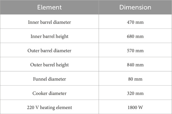
Table 2. Characteristics of the setup for the internal cooker system in Figure 6a.
The oil properties change with the temperature. The key characteristics of the oil applied in the systems with internal and external cookers (Duratherm) in the temperature range 40–200
• Dynamic viscosity: 29–1.2
•Density: 848–743
•Heat capacity: 2.0–2.5
The results of the experiments with the integrated cooker are reflected in the following section.
6.2 Results
The control system was tested for both charging (heating) and discharging (cooking).
6.2.1 Comparisons of charging with and without a flow barrier
Figure 7 shows the differences in charging with and without a barrier. Without a barrier, the circulation starts immediately after power is initiated on the heating element. The temperature in the cooker, therefore, increases slowly, and useful energy would not be available in the system before the full storage has been well charged. With a barrier hindering the circulation, the power is transferred to heating the oil in the funnel alone, and cooking can start after a short time. This illustrates that without a sort of temperature control, an oil-based sensible heat system would be somewhat impractical to use as it would always be necessary to wait for the whole storage to be charged until sufficiently high oil temperatures for cooking are reached.
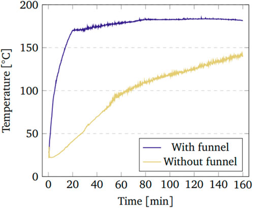
Figure 7. Experiments with and without a flow barrier during charging of the system with an internal cooker (Figure 6a).
6.2.2 Charging with the flow barrier
Figure 8a shows the behavior of the system being charged with 1.8 kW power and a fixed barrier in place. The following can be noted: the temperature in the cooker increases rapidly and then becomes near-constant after the oil level reaches the barrier and overflow initiates circulation (red line). The top temperature on the storage side increases and becomes near-constant after overflow starts (blue line). The temperature sensors further down in the storage show increasing values in time as the thermal front moves downward (gray lines). After the hot oil front reaches the bottom of the storage (blue line), hot oil now enters the funnel with the heating elements, and the cooker temperature will also increase again from then on. The heating element then needs to be shut off, and a thermostat switch is needed to not exceed a certain maximum temperature for the oil.
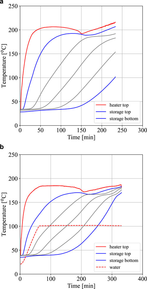
Figure 8. Charging experiments with an internal heater and cooker system (system in Figure 6). (a) Charging of the system with an internal cooker (Figure 6a). (b) Charging of the system with an internal cooker (Figure 6a) while boiling 5 L of water.
Figure 8b shows a similar case, but now with heating of 5 L of water taking place also during the charging. The oil in the cooker transfers the heat to the pot with water. If the oil reaches sufficiently high temperatures for overflow across the barrier to occur, the excess energy is transferred to the storage side by initiation of circulation. A low power on the heating element would lead to delayed overflow, if overflow would happen at all. For the case in Figure 8b, the power is quite high, and circulation starts quite soon, indicating that excess energy is transferred to the storage side. The characteristics of the temperature curves are similar to those in the case without cooking, except that the storage temperatures become lower for the cooking case as energy is required for cooking. The expansion-based control method thus should inherently be able to accept varying cooking power (e.g., varying power from photovoltaic panels) and still maintain cooking by shedding excess energy to the storage side.
6.2.3 Discharging with barrier control
Figure 9 shows two cases where cooking is done with energy from the storage side, and the heating element is without power.
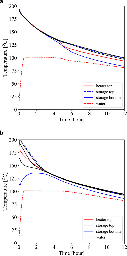
Figure 9. Discharging experiments with an internal heater and cooker system (system in Figure 6). (a) Boiling liters of water on a heat storage with aninternal cooker (Figure 6a). Uniform initial temperature in the storageand a high barrier position. (b) Boiling 5 L of water on a heat storage with aninternal cooker (Figure 6a). Stratified initial temperature in the storageand a low barrier position.
The first case in Figure 9a is with the barrier in a quite high position and with a fully charged heat storage. Five liters of water is brought to boiling temperatures in approximately 30 min, and boiling is maintained for approximately 4 h before the oil level reaches the barrier due to contraction from decreasing temperatures. Circulation then stops prematurely at the barrier, and the whole system gradually cools down due to thermal losses. A low barrier position is tested for discharging in Figure 9b. In this case, the heat storage is also not fully charged; the bottom temperature starts at approximately 110
The tests with the cooker integrated with the storage shows that with barrier control, cooking can start early when power is available (high barrier position) and can be maintained until low storage temperatures when relying on the storage energy (low barrier position).
7 System with an external heater and cooker
7.1 Materials and methods
Figure 10 shows the second method with the storage and the cooker as two separated units. This can be practical for up-scaling of the systems as the storage can also be positioned outside a wall with the cooker unit inside. The dimensions of the storage and the cooker are similar to that with the internal cooker (see Table 2), but now with 60 mm internal diameter connecting pipes between the two parts. The system has 10 cm insulation of the type FyreWrap, and all experiments have been conducted indoors in the laboratory.
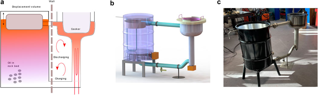
Figure 10. System with an external cooker. (a) System with an external cooker and a displacement body forlevel control. (b) Drawing of the system with an external cooker. (c) System with an external cooker before insulation.
Barrier solutions were also evaluated for the external cooker system, Figure 11a. A pipe bend inserted into the upper connecting pipe fulfilled the requirement for simplicity, and with a sufficient length of the pipe-in-pipe arrangement, any bypass leakages could be limited, which is an important factor as the barrier concept does not tolerate even a small leakage. Rotating the pipe bend worked quite well as a way of changing the overflow height, but access to the bend pipe in the storage unit could become somewhat cumbersome. An upward-moving gate valve was considered in the connecting upper pipe but was abandoned due to the high costs of temperature-tolerant valves for the relatively large diameters of the connecting pipes. A second option, involving a rotating barrier with a larger diameter than the connecting pipe and positioned on the cooker side, was evaluated, but it was not pursued as it would be more complicated both geometrically and operationally.
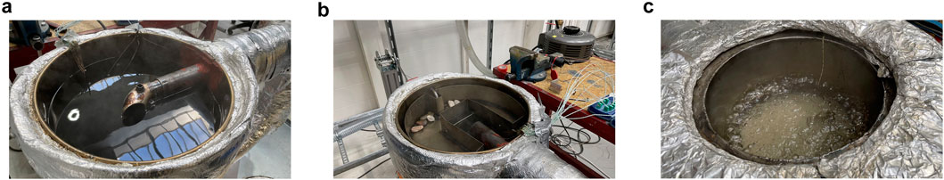
Figure 11. Level controls for system with an external cooker. (a) System with an external cooker (Figure 10a). Rotating a pipe bend for flow barrier control (Figure 10a). (b) System with an external cooker (Figure 10a). Displacement body for level control. (c) System with an external cooker (Figure 10a). Boiling water on the heat storage. The oil flow around the cooker is nonsymmetric, but boiling isquite uniform.
Instead of moving the barrier, a method based on changing both oil levels in the storage and in the cooker by adjusting the position of a displacement body in the storage tank was adopted, see Figure 11b. The displacement body can be controlled via a wire arrangement or a direct mechanical connection. The use of a displacement body can also give more flexibility with respect to the initial oil level in the system; it does not require calibration to a given initial barrier level. It is also easier to obtain a larger control band with the displacement solution than with the barrier for the case of the external cooker system. Although the flow geometry of the cooker is not symmetric, in most cases, the boiling appeared to be sufficiently uniform, see Figure 11c. The results of the experiments with the external cooker system are provided in the following section.
7.2 Results
Cooking tests with the external cooking arrangement were performed with and without power on the heating element.
Figure 12a shows a case with 1.8 kW power on the heating element, starting from cold temperatures. The barrier is positioned such that overflow and circulation are hindered, and the energy in the hot oil in the funnel below the cooker is used to heat the water rather than being transferred to the storage side. The temperature at the bottom also increases (red color) as there is no inflow at the bottom from the storage side. Circulation begins when the barrier is lowered (vertical dotted line), resulting in increasing temperatures at the top of the storage and decreasing temperatures at the lower inlet of the funnel due to cold oil now entering from the storage side. Boiling is terminated at the second barrier adjustment (vertical dotted line), and the plot shows the subsequent propagation of the thermal front through the storage. After approximately 5 h, the front reaches the bottom of the storage. Figure 12b also shows the shape of the thermal front as it propagates through the storage during the experiment.
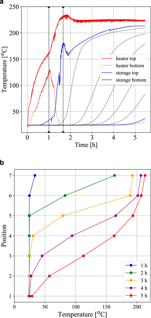
Figure 12. Charging experiments on the system with an external cooker (Figure 10). (a) System with an external cooker (Figure 10a). Boiling 5 L of water with 1.8 kW on the heating element. Regulation of flow barrier at two times. The gray lines represent temperature recordings in the heat storage, from top to bottom. (b) System with an external cooker (Figure 10a). Time evolution of temperature profiles in the heat storage during charging. Position 1 is at the bottom and 7 is at the top of the storage.
The performances of the displacement body for flow regulation are demonstrated in Figure 13.
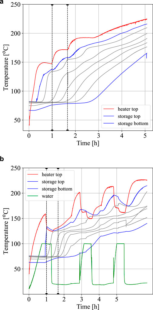
Figure 13. System with external cooker. Temperature control with displacement body. (a) System with an external cooker (Figure 10a). Temperature control with a displacement body during charging. Regulation of the displacement body at two times. The gray lines represent temperature recordings in the heat storage, from top to bottom. (b) System with an external cooker (Figure 10a). Temperature control with displacement body during charging and with boiling of 5 L of water thrice. Regulation of the displacement body at two times. The gray lines represent temperature recordings in the heat storage, from top to bottom.
When starting with power on the heating element in Figure 13a, the temperature in the funnel increases until the overflow level is reached after approximately 1/3 of an hour. The initial temperature in the storage, from the previous day, was approximately 70–80
A case of cooking while charging with the displacement regulator is shown in Figure 13b. The cooker temperature (green line) initially increases fast and then at a slower rate as the water temperature approaches boiling values. After some boiling time, the boiling rate was reduced to simmering (vertical dotted line), by lowering the displacement body to increase the circulation rate. The funnel temperature decreases, and the thermal front also propagates downward in the storage side at a lower front temperature. After the boiling water was removed, the displacement body was adjusted again (dotted vertical line) to regain a higher rate of increase in the funnel temperature. A similar procedure with boiling water was repeated two more times. It can be observed that as the initial thermal front reaches the bottom of the storage, it also becomes increasingly more difficult to reduce the boiling rate by moving the displacement body. At some point, the power on the element has to be reduced or stopped, similar to the pure charging case.
Cooking on energy from the storage alone, without power on the heating element, is shown in Figure 14. In a near-fully charged heat storage, as shown in Figure 14a, 5 L of water could be brought to boiling temperatures approximately 8 times, where the last case is observed to be kept at simmering temperatures for approximately 2 hours, even with oil temperatures only slightly above the boiling temperatures.
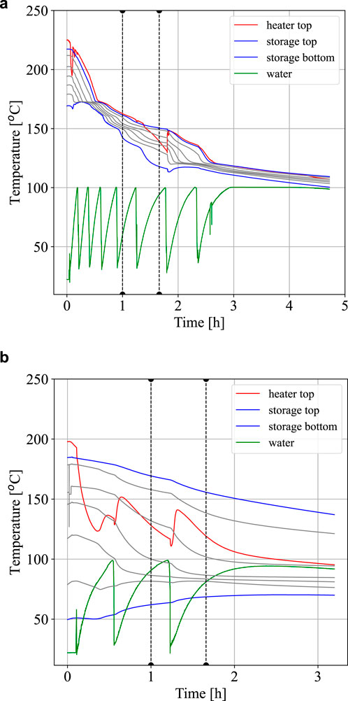
Figure 14. Discharging experiments on the system with external cooker. (a) System with external heat storage. Boiling 5 liters of water on a near-fully charged heat storage. (b) System with external heat storage. Boiling 5 liters of water on a partially charged heat storage.
A weakness with the external cooker case is shown in Figure 14b where cooking is made on a partially charged heat storage with the bottom of the storage cold and the top layer of the storage hot. The water draws heat from the funnel, and the circulation does not replenish sufficiently from the storage side. The circulation stops when the average gravity terms are equal on each side, and this can be the case also with a storage which is colder than the funnel at the bottom part and hotter than the funnel at the top part. This weakness is not observed whenever the bottom temperature in the storage part is above the water boiling point.
8 Discussion
Sensible heat storage solutions for cooking often have the weakness that the whole storage must be charged to high temperatures before the stored energy can be used for cooking. An oil-based system with circulation between a heater and a storage can offer an improvement if thermal stratification in the storage can be obtained, where hot oil is at the top and cold oil is at the bottom. A temperature regulation method is then required to feed the heat storage with an oil at a set temperature. Discharging can be done with reversed flow so that oil with the high top temperature can power a cooker, enabling the use of energy for cooking also from a partially charged heat storage.
An objective of the work was to test a method for temperature regulation that is simple and robust, without using circulation pumps, sensors, and actuators, such that it could be constructed and maintained in a rural African environment. The results of the present work show good performance of a method with natural circulation between a heater with a cooker and a heat storage. The temperature regulation method is based on the expansion of the heat transfer oil and control of a flow barrier between the heater and storage.
The temperature regulation method for was first conceptually tested in two small-scale setups and then applied in two pilot systems for cooking. In the first pilot, the heater and cooker are integrated in the storage, and the regulation is done by adjusting a flow barrier. In the second pilot, the heater with the cooker is placed outside the storage. The flow in the connecting pipes can be regulated using a displacement body in the storage, which can change the oil levels in the two parts. Both systems are mechanically very simple to produce and to operate.
The external cooker can have some benefits as the storage can be located outside a wall and thus also allow for more insulation without claiming excess indoor space. Another benefit of the external cooker is that the funnel can be well insulated such that high storage temperatures can be obtained in the funnel even with low power levels on the heating element. However, thermal losses to the ambient can lead to slow heating and weak circulation rates; proper insulation is essential for harvesting low-power energy. The funnel in the internal cooker case is more difficult to insulate, and heat leakage to the storage side around the funnel will cause lower circulation rates and lower performance at low heating powers.
At the start of the work, it was not clear whether the natural circulation rate would be sufficient to provide ample cooking power. The tests confirm that the time to reach boiling temperatures of 5 L of water is acceptable, both during charging and discharging of the heat storage (10–30 min). Furthermore, the flow barrier could be regulated to maintain low circulation rates to keep simmering for long times.
It was also important to verify that near-steady-state flow conditions could be achieved during charging to obtain stable temperatures of the oil entering the storage. A steady-state flow rate is a result of the balance between the gravitation and friction in the system, integrated around the flow path. The convective heat transfer in the funnel is then balanced through the power on the heating element, for an ideally insulated system. The results of the small-scale tests showed that for a high heating power, the steady-state condition was not reached, and the temperature in the cooker side increased instead of leveling out in time. The tests with the cooker pilots show that this is not a problem with the applied 1.8 kW heating power, and the systems are quite well behaved in this respect.
The flow rate changes as the oil viscosity decreases with increasing temperatures. However, the tests show that near-steady conditions prevail in the heating funnel as long as the inlet temperatures (the bottom temperature in the storage) are constant. When the thermal front in the heat storage reaches the bottom of the storage and the inlet of the funnel, the temperatures in the funnel increases, and the flow rate also changes with the subsequent decreasing oil viscosity. The startup time for the oil level to reach the barrier by expansion is less affected by the viscosity and mainly depends on the heat capacity, which is weakly dependent on the temperature.
The thermal stratification in the heat storage will decay in time due to thermal conduction, and the heat storage will eventually approach uniform temperatures, typically after one night in the present cases. The thermocline will also widen somewhat as the front propagates down the heat storage, as can be noted in the figures showing the temperatures during charging of the storage. The installation of flow guides were considered to reduce the possibilities for fluid mixing at the top of the storage tank, but the testing showed that this was not required. Symmetry is ensured at the inlet and outlet of the storage tank, and the fluid velocities in the tank are very low.
There are two safety aspects related to the oil heating. One is oil overheating to the point where it can smoke or cause fire, and a thermostat shut-off switch is needed to avoid this scenario. The other aspect is to ensure in the design that there is no access to the oil from the top of the cooker as water intrusion into hot oil can cause vapor explosion. The two pilots have side shields to avoid access to the oil, but they are not sealed so the pressure in systems is always at atmospheric values. A connection with an expansion tank would be required for a completely sealed system. The hot oil will be exposed to air in the atmospheric system and is expected to degrade with time. The tests with different oil samples exposed to air for a period of a year showed that the properties of the thermal oil were conserved, whereas those of the edible oils changed. For a closed system, the oil in an expansion tank will be cold, and the oxidation problem is then expected to be minor. It remains to be observed how long the oil can be exposed to heat cycling before degrading, but thermal oils are often used for years before substitutions are required.
Realistic tests with cooking of relevant food items and with varying PV power have been made at Makerere University in Uganda, Chaciga et al. (2025), where a pilot unit of the external cooker system was constructed based on the experiences from the present laboratory work. A rock bed is included in the heat storage, and an MPPT controller (without battery) was used for the connection to PV panels providing power up to 1 kW. The cooking tests are convincing, and the system is, in particular, suitable for cooking food requiring long cooking times (e.g., beans).
The results of the current work can serve to motivate people working with energy for cooking to focus on heat storage solutions to increase the likelihood of adoption of solar cooking technology. Further work is encouraged, and in particular, on the heating side. As the circulation in the system is temperature-controlled, the methodology is open for hybrid solar and wind power by adding separate heating elements.
Data availability statement
The raw data supporting the conclusions of this article will be made available by the authors, without undue reservation.
Author contributions
ON: Conceptualization, Data curation, Formal analysis, Funding acquisition, Methodology, Project administration, Software, Supervision, Writing – original draft. PM: Data curation, Investigation, Methodology, Writing – review and editing. GN: Data curation, Investigation, Methodology, writing – review and editing. AB: Data curation, Investigation, Methodology, Writing – review and editing. AO: Data curation, Investigation, Methodology, Writing – review and editing. JC: Investigation, Validation, Writing – review and editing.
Funding
The author(s) declare that financial support was received for the research and/or publication of this article. The experimental costs were funded by NORAD under the Energy and Petroleum Program (EnPe) and the Norwegian Programme for Capacity Development in Higher Education and Research for Development (NORHED II). The EnPe and NORHED programs support collaboration with African partner universities.
Acknowledgments
Support of Paul Svendsen et al. in construction of the systems in the laboratory at the Department of Energy and Process Engineering at NTNU is gratefully acknowledged. ON acknowledges support from NTNU for sabbatical periods in Tanzania and Uganda.
Conflict of interest
The authors declare that the research was conducted in the absence of any commercial or financial relationships that could be construed as a potential conflict of interest.
Generative AI statement
The author(s) declare that no Generative AI was used in the creation of this manuscript.
Publisher’s note
All claims expressed in this article are solely those of the authors and do not necessarily represent those of their affiliated organizations, or those of the publisher, the editors and the reviewers. Any product that may be evaluated in this article, or claim that may be made by its manufacturer, is not guaranteed or endorsed by the publisher.
References
Aramesh, M., Ghalebani, M., Kasaeian, A., Zamani, H., Lorenzini, G., Mahian, O., et al. (2019). A review of recent advances in solar cooking technology. Renew. Energy 140, 419–435. doi:10.1016/j.renene.2019.03.021
Arunachala, U. C., and Kundapur, A. (2020). Cost-effective solar cookers: a global review. Sol. Energy 207, 903–916. doi:10.1016/j.solener.2020.07.026
Chaciga, J., Okello, D., Nyeinga, K., and Nydal, O. J. (2025). Experimental analysis on a solar photovoltaic indoor cooker integrated with an energy storage system: a positive step towards clean cooking transition for sub-saharan africa. Sol. Compass 13, 100109. doi:10.1016/j.solcom.2025.100109
Cuce, E., and Cuce, P. M. (2013). A comprehensive review on solar cookers. Appl. Energy 102, 1399–1421. doi:10.1016/j.apenergy.2012.09.002
Gomna, A., N’Tsoukpoe, K. E., Le Pierrès, N., and Coulibaly, Y. (2019). Review of vegetable oils behaviour at high temperature for solar plants: stability, properties and current applications. Sol. Energy Mater. Sol. Cells 200, 109956. doi:10.1016/j.solmat.2019.109956
Hoffmann, J.-F., Vaitilingom, G., Henry, J.-F., Chirtoc, M., Olives, R., Goetz, V., et al. (2018). Temperature dependence of thermophysical and rheological properties of seven vegetable oils in view of their use as heat transfer fluids in concentrated solar plants. Sol. Energy Mater. Sol. Cells 178, 129–138. doi:10.1016/j.solmat.2017.12.037
Kahsay, M. B., and Nydal, O. J. (2023). Degradation of viscosity of vegetable oils employed for thermal energy storage due to oxidation in ambient temperature. J. Energy Storage 73, 108816. doi:10.1016/j.est.2023.108816
Lentswe, K. O. P., Mawire, A., Owusu, P., and Shobo, A. (2021). A review of parabolic solar cookers with thermal energy storage. Heliyon 7. doi:10.1016/j.heliyon.2021.e08226
Mahavar, S., Kuldeep, P., and Mawire, A. (2025). Study of sunflower oil for heat transfer and storage applications. Sci. Afr. 28, e02653. doi:10.1016/j.sciaf.2025.e02653
N’Tsoukpoe, K. E., Pierrès, N. L., Seshie, Y. M., and and, Y. C. (2021). Technico-economic comparison of heat transfer fluids or thermal energy storage materials: a case study using jatropha curcas oil. Afr. J. Sci. Technol. Innovation Dev. 13, 193–211. doi:10.1080/20421338.2020.1838082
Nydal, O. J. (2023). Heat storage for cooking: a discussion on requirements and concepts. Energies 16, 6623. doi:10.3390/en16186623
Sharma, A., Chen, C. R., Murty, V. V. S., and Shukla, A. (2009). Solar cooker with latent heat storage systems: a review. Renew. Sustain. Energy Rev. 13, 1599–1605. doi:10.1016/j.rser.2008.09.020
Keywords: thermal energy storage, heat storage for cooking application, solar thermal, oil-based heat storage, clean cooking
Citation: Nydal OJ, Mashingo P, Nylund GH, Bjørshol A, Olsen AP and Chaciga J (2025) Passive temperature regulation in a heat storage for cooking with internal natural oil circulation. Front. Energy Res. 13:1627862. doi: 10.3389/fenrg.2025.1627862
Received: 13 May 2025; Accepted: 23 June 2025;
Published: 18 August 2025.
Edited by:
Xinyu Huang, Xi’an Jiaotong University, ChinaReviewed by:
Abdulrazzaq Mohammed Salih, University of Tikrit, IraqSandy Khoury, Saint Joseph University, Lebanon
Copyright © 2025 Nydal, Mashingo, Nylund, Bjørshol, Olsen and Chaciga. This is an open-access article distributed under the terms of the Creative Commons Attribution License (CC BY). The use, distribution or reproduction in other forums is permitted, provided the original author(s) and the copyright owner(s) are credited and that the original publication in this journal is cited, in accordance with accepted academic practice. No use, distribution or reproduction is permitted which does not comply with these terms.
*Correspondence: Ole Jorgen Nydal, b2puQG50bnUubm8=
†Deceased