 Yunseok Jeong
 Yonghee Kim
- Department of Nuclear and Quantum Engineering Korea Advanced Institute of Science and Technology (KAIST), Daejeon, Republic of Korea
This study investigates the feasibility of Daily Load-Follow Operation (DLFO) for the Autonomous Transportable On-demand Reactor Module (ATOM), a Soluble Boron-Free (SBF) small modular reactor (SMR). The ATOM core was selected as a reference model due to its adoption of key SBF-compatible design features, including Centrally-Shielded Burnable Absorbers (CSBAs)—burnable absorbers with controlled self-shielding—and a Truly-Optimized Pressurized Water Reactor (TOP) lattice, which employs enhanced moderation to ensure favorable neutron economy and temperature feedback. Together, these features provide stable excess reactivity and favorable Moderator Temperature Coefficient (MTC) characteristics across the reactor cycle. To enable effective reactivity and axial power distribution control in such an environment, the Mode-Y control logic was applied. Mode-Y is a newly developed control strategy that relies solely on Control Element Assembly (CEA) movements and allow independent insertion of gray banks by eliminating conventional overlap constraints. A challenging DLFO scenario was simulated at three representative burnup conditions—Beginning-of-Cycle (BOC), Middle-of-Cycle (MOC), and approximately 90% End-of-Cycle (EOC)—to evaluate the performance of Mode-Y control logic. The scenario involved rapid power ramps with 50%p changes within 3 h, followed by irregular hold periods, to test the control logic under highly dynamic conditions. The analysis employed a conventional two-step approach: multigroup cross-sections were generated using the SERPENT2 Monte Carlo code with ENDF/B-VII.1 library, and whole-core transient simulations were performed using KANT nodal diffusion code. Results confirm accurate power tracking, stable Axial Shape Index (ASI) control, acceptable coolant temperature management, and sufficient nodal and pin-wise power peaking margins throughout all burnup stages.
1 Introduction
In recent years, the nuclear energy sector has shifted its focus from traditional large-scale Pressurized Water Reactors (PWRs) to Small Modular Reactors (SMRs). Unlike large reactors that rely on the economy of scale, SMRs use the economy of multiples to add capacity incrementally without a large upfront investment (Mignacca and Locatelli, 2020; Locatelli et al., 2014). This makes SMRs particularly appealing in regions with smaller or variable energy demands, where constructing a single large reactor may not be economically viable (Locatelli et al., 2014). SMRs place key components—like the heat exchanger and steam generator—inside the pressure vessel. This integration simplifies the system, enhances afety, and may shorten construction time (Ilyas and Aydogan, 2017; Cheng, 2020). SMRs also offer the flexibility to be deployed in remote locations or areas with limited grid infrastructure, making them a versatile option for diverse energy needs (International Atomic Energy Agency, 2018; International EnergyForum, 2021).
As the global energy landscape evolves, SMRs are increasingly viewed as a flexible solution to complement renewable energy sources and address variable power demands (Mignacca and Locatelli, 2020; Dong et al., 2021). However, for SMRs to realize their full potential, they must meet stringent operational requirements, including the ability to respond rapidly to changes in power demand (Mignacca and Locatelli, 2020; Jenkins et al., 2018). This capability is particularly critical for maintaining grid stability in energy systems with significant contributions from intermittent renewable sources or in isolated regions with fluctuating consumption patterns (Jenkins et al., 2018). For instance, SMRs must handle scenarios where power output needs to be adjusted quickly to balance supply-demand mismatches caused by renewable energy variations (Dong et al., 2021; Jenkins et al., 2018). These conditions necessitate not only robust reactor designs but also advanced control strategies to ensure safe and reliable operation. Ensuring that SMRs can reliably perform under such conditions is a key step toward their broader adoption and competitiveness in modern energy markets.
The Autonomous Transportable On-demand Reactor Module (ATOM) is a next-generation SMR specifically designed for operation in a Soluble Boron-Free (SBF) environment. To achieve SBF operation, the ATOM core employs innovative strategies to manage reactivity and thermal stability throughout the fuel cycle. One key feature is the Centrally-Shielded Burnable Absorber (CSBA), which has a 3-D structure embedded inside fuel pellets. This configuration optimizes spatial self-shielding and ensures gradual depletion of the absorber material, thereby minimizing excess reactivity at the beginning of life (BOL) and stabilizing reactivity changes over time (Nguyen et al., 2019; Nguyen and Kim, 2021; Wijaya et al., 2024). This approach improves reactivity control while maintaining a stable axial power distribution. At the same time, SBF operation also avoids issues associated with soluble boron, such as near-zero Moderator Temperature Coefficients (MTCs), crud deposition, slow reactivity responses, and material corrosion (Nguyen and Kim, 2021). By removing the reliance on Chemical and Volume Control Systems (CVCS), the reactor design becomes simpler and inherently safer, reducing operational costs and waste production. However, this shift places greater reliance on Control Element Assembly (CEA) movements and requires innovative control strategies to manage reactivity and thermal feedback effectively under dynamic conditions, such as load-follow operations and reactor startup (Abdelhameed et al., 2018).
A critical challenge in SBF reactors is implementing effective control logic to compensate for changes in reactivity and axial power distribution during load-follow operations. Previous studies have addressed this problem using various approaches. Li Wang et al. explored the feasibility of Daily Load-Follow Operation (DLFO) without soluble boron adjustments in the CPR1000 reactor by regrouping CEAs into two sets: one for reactivity and temperature control, and the other for Axial Shape Index (ASI) control (Wang et al., 2014). Similarly, Yawei Zhang et al. analyzed the same reactor design by modifying the number and placement of CEAs while keeping the original control logic unchanged, achieving enhanced DLFO performance without boron adjustments (Zhang et al., 2015).
In France, Mode-X control logic was implemented in the N4 reactor to support load-follow operations in a soluble boron environment. Mode-X provides two operational modes: one using control rods alone to compensate for xenon poisoning and the other combining boric acid adjustments with control rod movements. However, Mode-X requires that all control rods be fully withdrawn or minimally inserted before starting DLFO, which imposes specific operational constraints. This operational condition, while effective in maintaining stability during boron-assisted load-follow scenarios, poses challenges when transitioning to boron-free designs, where reactivity adjustments rely solely on control rods (OECD/NEA, 2021). Furthermore, Mode-X relies on fixed rod overlap configuration and typically uses top-inserted black banks to maintain a bottom-skewd axial power shape. This configuration limits flexibility in reactivity control and complicates its extension to SMRs.
In Korea, Mode-K was initially developed as a control logic for the Korea Next-Generation Reactor (KNGR), serving as the foundation for subsequent reactor designs, including the APR1400 (Kim et al., 1999; Kim and Park, 2000). Mode-K was later refined into Mode-K+, an advanced control strategy specifically designed for load-follow operations in the APR1400 reactor, which operates with soluble boron. Mode-K+ primarily incorporates boron concentration adjustments and the use of Partial Strength Control Element Assemblies (PSCEAs) during load-follow operations to optimize reactivity control and axial power. Additionally, Mode-K+ explores scenarios where boron concentrations remain unchanged, aiming to reduce reliance on soluble boron in PWRs like the APR1400 while still addressing challenges associated with xenon-induced axial oscillations and reactivity feedback under deeply decreased power conditions (Khalefih et al., 2023; Khalefih and Kim, 2024a; Khalefih and Kim, 2024b; Khalefih et al., 2025).
Building on these prior works, this study introduces and evaluates the Mode-Y control logic, designed to enhance the operational flexibility and performance of soluble boron-free reactor cores (Jeong et al., 2023; Jeong, 2021). Mode-Y provides an innovative approach by assuming a zero-boron environment from the outset and relying entirely on mechanical control via a dedicated combination of gray and regulating CEAs. Specifically, 2 Gy banks (GR2 and GR1) operate fully independently with non-overlapping insertion depths to finely adjust reactivity while minimizing axial shape distortion, whereas the regulating black bank (R2) is allowed to overlap with GR1 to expand the control range during rapid transients. By employing relatively narrow dead-bands in its control logic, Mode-Y ensures stable operation without significant overshoot or oscillation, even under irregular or rapid power maneuvering. This enables smooth and autonomous reactivity regulation in response to changes in coolant temperature and ASI. The Mode-Y logic avoids fixed initial insertion constraints and is inherently compatible with SMR environments, where design simplicity, chemical system elimination, and autonomous operation are of high priority.
In this study, the Mode-Y control logic is applied to the ATOM SMR core, which is designed for SBF operation using CSBA. The objective is to evaluate whether Mode-Y enables stable and effective DLFO over the entire reactor cycle, with particular focus on reactor power control, ASI regulation, and thermal margin under dynamically changing conditions. Load-follow scenarios involving rapid and irregular power variations were simulated at three representative burnup stages: beginning-of-cycle (BOC), middle-of-cycle (MOC), and 90% end-of-cycle (EOC). The analysis was conducted using the in-house 3-D nodal diffusion code KANT (Oh et al., 2023), with multigroup cross-section data generated by the SERPENT2 Monte Carlo code (Leppänen et al., 2015). The neutronic calculation was coupled with thermal-hydraulic feedback, and the cross-section library was prepared based on temperature-branch calculations to account for thermal feedback effects. Mode-Y was implemented in KANT through a flag-based control logic that determines CEA movements in response to deviations in coolant temperature and ASI. This paper is organized as follows. Section 2 revisits the ATOM core design, highlighting the TOP lattice and overall configuration. Section 3 describes the Mode-Y control logic and its implementation. Section 4 provides simulation results and discusses the performance of Mode-Y throughout the reactor cycle. Finally, Section 5 concludes the key findings and outlines future research.
2 Core configuration of ATOM
2.1 Truly-Optimized PWR lattice
The Truly-Optimized PWR (TOP) lattice is developed to take advantage of the design flexibility enabled by SBF operation, particularly by optimizing the hydrogen-to-uranium (H/U) ratio in the absence of borated water. In conventional PWRs, fuel assemblies are intentionally under-moderated to compensate for the strong positive reactivity feedback introduced by soluble boron, which is less favorable in terms of neutron economy. However, under SBF conditions, this design constraint is lifted, allowing the FA geometry to be adjusted toward a more neutronically optimal moderation regime. The TOP lattice incorporates a higher moderator fraction to achieve a softer neutron spectrum, improving neutron economy and enabling a sufficiently negative MTC throughout the reactor cycle under SBF condition (Nguyen et al., 2019).
Two approaches have been proposed to implement the TOP lattice: (1) increasing the pin pitch while maintaining the conventional fuel radius, and (2) reducing the fuel pellet radius while preserving the standard assembly geometry. In the core design revisited in this study, the second approach is adopted, in which the fuel radius is reduced to 0.38 cm while maintaining a 1.26 cm pin pitch. This configuration offers a practical balance between enhanced neutron moderation and compatibility with existing 17 × 17 PWR assemblies, making it suitable for near-term deployment (Nguyen and Kim, 2021).
The smaller fuel radius TOP lattice is further optimized by incorporating eight Er2O3-bearing fuel rods positioned adjacent to the guide tubes (Wijaya et al., 2024). This addition effectively reduces early excess reactivity by approximately 400 pcm at the BOL and mitigates local power peaking factors, particularly during the initial operation. The impact of Er2O3 diminishes beyond 30 GWd/tU, introducing only a negligible reactivity penalty later in the cycle.
2.2 ATOM core design
The ATOM core is designed to operate efficiently in an SBF environment, where Burnable Absorbers (BAs) play a critical role in compensating for excess reactivity, while weak gray Control Rods (CRs) are utilized both to maintain criticality over the reactor cycle and to regulate reactor power during load-follow operations. To ensure gradual depletion of BAs and stable power distribution over the reactor cycle, cylindrical Centrally-Shielded Burnable Absorbers (CSBAs) are adopted. These BAs offer adjustable self-shielding characteristics by tuning their Height-To-Diameter (HTD) ratio and quantity per fuel rod. In particular, the axial zoning of CSBA volume mitigates the bottom-skewed power distribution resulting from the strongly negative MTC, which tends to increase power in the lower core region at low coolant temperature (Wijaya et al., 2024). The core consists of 69 TOP 17 × 17 FAs, each containing CSBA-loaded UO2 fuel rods enriched to 4.95 w/o. Additionally, the core has blanket regions with a thickness of 5 cm at both the top and bottom, where CSBA is not used. Instead, UO2 fuel rods enriched to 3 w/o and 2 w/o are used in these regions. The main design parameters and schematic layouts are shown in Table 1 and Figure 1. An in-then-out shuffling scheme is applied to enhance neutron economy, as illustrated in Figure 2, which also shows zone-wise CSBA patterns used to suppress local power peaking.
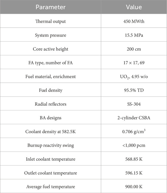
Table 1. Major design parameters of the ATOM core (Wijaya et al., 2024).
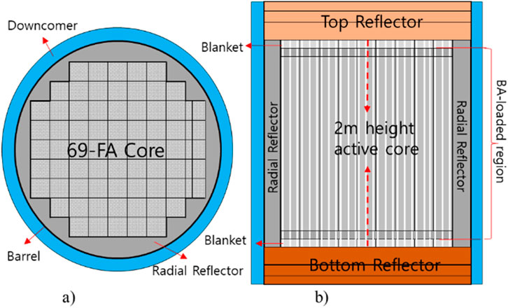
Figure 1. Radial and axial core layout (Wijaya et al., 2024). (a) Radial layout. (b) Axial layout.
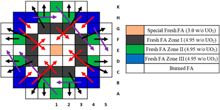
Figure 2. Two-batch fuel management scheme (Wijaya et al., 2024).
To manage reactivity and axial power distribution, the ATOM core employs a checker-board CR pattern, as shown in Figure 3, with specifications listed in Table 2. The CR configuration includes 20 shutdown CEAs, 12 regulating CEAs, and 5 Gy CEAs. Shutdown rods use boron carbide (B4C) with 90 w/o B-10. Regulating rods are divided into two types: one type uses B4C containing 50% enriched B-10, and the other uses B4C with natural boron. In the DLFO simulations, R1 bank is not directly used because its high rod worth induces strong power distortion. It is mainly employed during reactor startup process to compensate xenon worth. To enhance the cold shutdown margin, 12 shutdown CEAs are extended, incorporating additional fingers from neighboring FAs, resulting in configurations with 34, 36, or 39 fingers. Gray rods (GRs), which utilize manganese (Mn) as the absorber material, are designed to balance reactivity without causing significant power distortions (Wijaya et al., 2024).
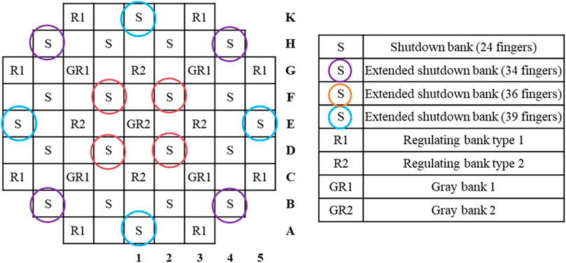
Figure 3. The checker-board CR pattern for the ATOM core (Wijaya et al., 2024).
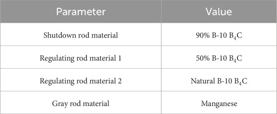
Table 2. CR specification of the ATOM core (Wijaya et al., 2024).
The equilibrium core characteristics discussed in this study are based on prior analyses performed using the Serpent2 Monte Carlo code with ENDF/B-VII.1 library. These results are revisited to assess the feasibility of load-follow operation under equilibrium conditions. The previous analysis demonstrated that the burnup reactivity swing is maintained below 1,000 pcm while achieving a 2-year cycle length and a discharge burnup of 43.2 GWd/tU. The evolution of keff and burnup characteristics are shown in Figure 4 and summarized in Table 3. This level of excess reactivity is sufficiently low to be controlled through gray rods, which is essential for SBF designs (Wijaya et al., 2024).
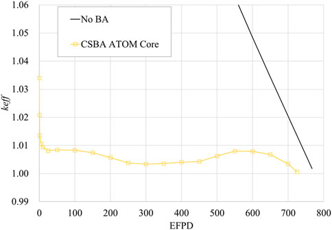
Figure 4. The multiplication factor evolution for the equilibrium core (Wijaya et al., 2024).
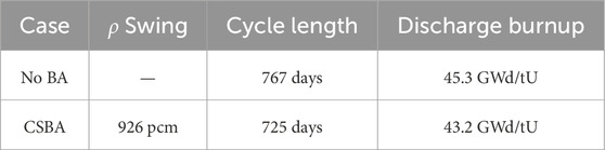
Table 3. Neutronic performance of the ATOM core (Wijaya et al., 2024).
The differential rod worths of gray banks GR2 and GR1 and regulating bank R1 were evaluated at three representative burnup conditions—BOC, MOC, and EOC—and are shown in Figures 5–7. The differential rod worth curves of GR2, GR1, and R1 exhibit distinct asymmetric patterns at BOC, MOC, and EOC. This trend arises from the heterogeneous axial and radial CSBA loading patterns, which cause spatially varying spectral conditions and power distributions that evolve with CSBA depletion. Since thermal-hydraulic feedback is consistently considered in the calculation, the observed rod worth profiles inherently reflect coupled neutronic–thermal-hydraulic effects.
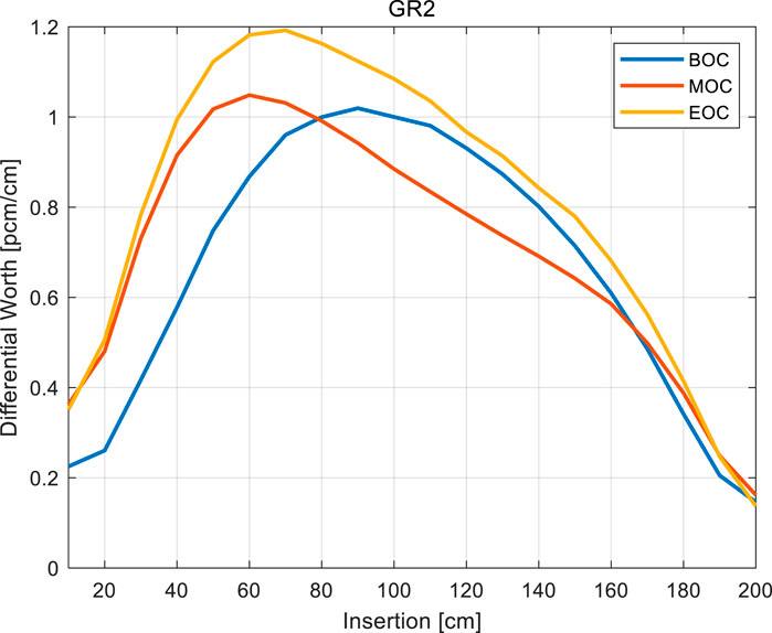
Figure 5. Differential worth of GR2 bank.
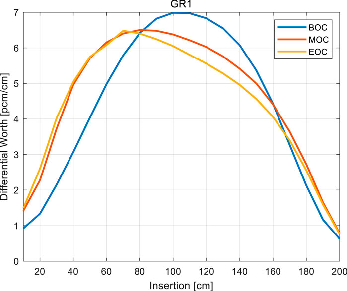
Figure 6. Differential worth of GR1 bank.
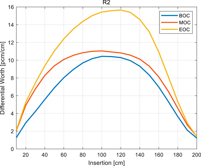
Figure 7. Differential worth of R2 bank.
The power distribution is also well-regulated throughout the cycle. Radial peaking remains below 1.40 at EOC, as shown in Figure 8, despite the low-leakage configuration of the core. Axial power profiles evolve in a controlled manner, transitioning from slightly bottom-skewed shapes to saddle-shaped distributions by EOC, as shown in Figure 9. These stable radial and axial power behaviors ensure that the core remains within safe operating margins during transient conditions (Wijaya et al., 2024).
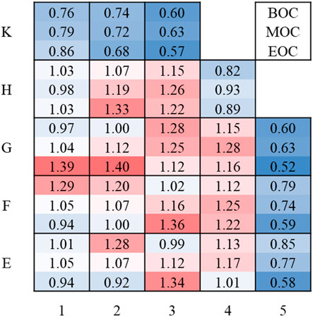
Figure 8. Radial assembly-power distribution of the ATOM core (Wijaya et al., 2024).
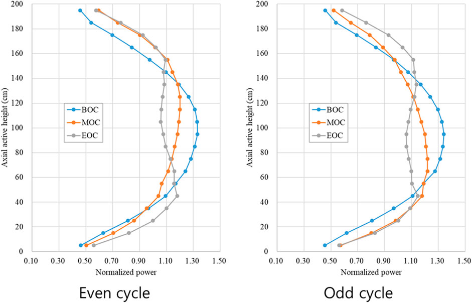
Figure 9. Axial power distribution of the ATOM core (Wijaya et al., 2024).
Temperature feedback behavior further reinforces the reactor’s load-follow capability. As summarized in Table 4, the MTC at Hot Full Power (HFP) remains strongly negative, measured at −52.9 pcm/K, and its variation between early and late stages of the cycle is limited to approximately 10 pcm/K. Under Hot Zero Power (HZP, 582.5 K) and Cold Zero Power (CZP, 298 K) conditions, the MTC and FTC maintain sufficiently negative values with minor variation across the reactor burnup. These temperature feedback coefficients confirm that the ATOM core possesses robust inherent safety characteristics, supporting simplified and reliable control during dynamic LFO scenarios (Wijaya et al., 2024).
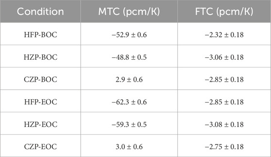
Table 4. Temperature coefficients of the ATOM core (Wijaya et al., 2024).
3 Mode-Y control logic
The Mode-Y control logic was developed for performing load-follow operations in SBF SMRs, emphasizing simultaneous control of reactor power and the axial shape index (ASI). This logic automatically manages the movement of each control element assembly to achieve target reactor core power and desired ASI levels. Control rod movement direction is determined based on the deviation between the measured average coolant temperature and its targeted value.
In the ATOM core, a constant average coolant temperature strategy is utilized (Wijaya et al., 2024). Unlike conventional PWRs, which employ a fixed inlet coolant temperature strategy, this approach can effectively mitigate power defects arising from variations in fuel and coolant temperatures during load-follow operations. Consequently, the inlet coolant temperature linearly decreases with reactor power.
The Mode-Y logic primarily regulates the reactor core power by maintaining the average coolant temperature within a predefined dead-band. When measured temperature deviation exceeds this dead-band, the logic selects appropriate CEAs and determines their movement direction. For instance, a negative temperature deviation indicates that reactor power is below the demanded level, prompting withdrawal of the selected CEAs to raise core power. Such rod movements continue until the temperature deviation returns safely within the dead-band, with sufficient margins provided to prevent overly frequent adjustments.
Figure 10 illustrates the relationship between temperature deviation (ΔT) and the temperature control flag activation. When ΔT exceeds the dead-band boundary T1, indicating that the measured temperature is higher than the target temperature, CEAs need to be inserted. The speed of insertion depends on how much the measured temperature exceeds the dead-band limits: if the deviation is greater than 0.3 °C, the CEAs move at a speed of 0.127 cm/s; however, if the deviation surpasses 0.8 °C, the insertion speed increases significantly to 1.27 cm/s. The control rod movements aimed at reducing the temperature deviation continue until the deviation returns by the amount of T2 from T1, at which point the flag state is reset. This logic similarly applies when the temperature deviation is negative (-T1). In the current study, the value of T2 is set to 0.55 °C for returning from high-speed movement and 0.15 °C from low-speed movement, respectively. Table 5 presents the detailed flag transition logic used in Mode-Y based on the temperature deviation. It outlines how the control flag state changes according to whether ΔT falls within or exceeds specific thresholds, distinguishing between low-speed and high-speed CEA movements for both insertion and withdrawal cases. The inclusion of the “Old Flag” in the table explicitly represents the prior state of the control logic, which is essential for determining whether a transition to a new flag state should occur under the given ΔT condition.
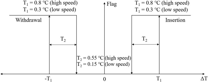
Figure 10. Temperature dead-band of Mode-Y.
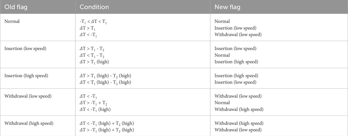
Table 5. Temperature deviation-based flag transition logic in Mode-Y.
Controlling the ASI within allowable limits is crucial, both for maintaining safety margins and optimizing fuel burnup (U.S. Nuclear Regulatory Commission (NRC), 2011). The target ASI is defined as the value observed in the equilibrium core without load-follow operation. Consequently, the deviation in ASI is determined by the difference between the current ASI and the initial ASI. Due to the relatively short axial length of SMRs, xenon oscillation-which can occur in large-scale PWRs-is typically negligible; nevertheless, careful ASI management remains essential to ensure an optimal axial power distribution. For example, decreasing reactor power by inserting a CEA into the upper half of the core may unintentionally increase the ASI, potentially resulting in undesirable bottom-skewed axial power distributions.
Figure 11 depicts how the ASI changes depending on the axial position and the directions of CEA movements during load-follow operations. Consequently, simultaneous ASI management is necessary during any CEA movements associated with load-follow operations. However, ASI control may be intentionally inactive under certain conditions when reactor power adjustments are needed but no favorable ASI control is available. Figure 12 illustrates the ASI dead-band and stage flag logic, similar in concept to the temperature dead-band shown previously. When the deviation in ASI (ΔASI) exceeds 0.03, it indicates that the axial power distribution is bottom-skewed. In this case, the control flag switches to ΔASI+, signaling the need to move CEAs in a direction that reduces the ASI. Conversely, when ΔASI drops below −0.03, it reflects a top-skewed power distribution, and the flag changes to ΔASI-, prompting CEA movements aimed at increasing the ASI. If the deviation in ASI remains within ±0.03, the flag is set to AAS (Acceptable ASI), indicating that no axial power adjustment is necessary. Once the ASI deviation returns by 0.015 from the threshold, the system reverts to the normal state, indicating that no further ASI adjustment is required. The detailed logic and corresponding flag conditions are summarized in Table 6.
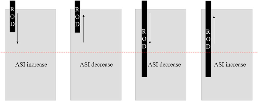
Figure 11. Effect of CEA movement direction and position and ASI.
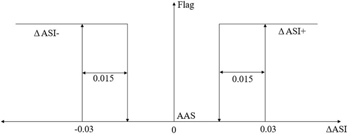
Figure 12. ASI dead-band of Mode-Y.
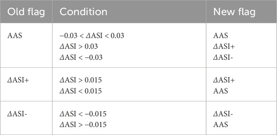
Table 6. ASI deviation-based flag transition logic in Mode-Y.
In Mode-Y, the control rod insertion follows a predefined sequence of GR2-GR1-R2-R1. This ordering is designed to balance reactor power control while maintaining a desirable axial and radial power distribution. Selection of proper CEAs for controlling power and ASI is based on stage flags derived from both temperature and ASI deviations. These include the temperature control flag (e.g., insertion or withdrawal at low/high speed depending on ΔT) and the ASI stage flag (e.g., ASI + when the core is bottom-skewed, ASI- when top-skewed). These flags determine whether a control rod movement is necessary as well as its direction and speed.
To enhance the effectiveness of ASI control, overlaps between gray rod banks—denoted as GR2 and GR1 in Figure 3—are eliminated. These two banks are configured to operate independently and, when necessary, can move in opposite directions solely to manage ASI. In contrast, the regulating banks are configured with a 50% overlap. Further details regarding the logic for selecting CEAs and determining their movement directions are provide in Tables 7–9. Specifically, the first table outlines the logic applied when CEA insertion is required, the second table covers the case for CEA withdrawal, and the third table describes the scenario in which temperature control is no longer necessary, but ASI adjustment is still needed. In these tables, B denotes the bottom of the core, and H represents the active core height. Within the “CEA Position” column, each bank name (e.g., GR2, GR1, R2) indicates the current axial position of the corresponding CEA. The “Effect” column categorizes the expected impact of each CEA movement from the perspective of ASI control: P (positive) refers to a movement that is expected to improve the ASI toward its target value, N (negative) indicates a movement likely to worsen the ASI deviation, and I (indeterminate) is used when the effect of the movement on ASI cannot be determined with certainty. As can be confirmed in the “Effect” columns of the tables, temperature control takes precedence over ASI control in the Mode-Y logic. Consequently, it is not always possible to achieve a positive effect on ASI, as certain CEA movements are primarily selected to satisfy temperature requirements, even if they may lead to a neutral or negative impact on the axial power shape. A simplified block diagram illustrating the Mode-Y control logic has been added as Figure 13 to clarify the overall logic.
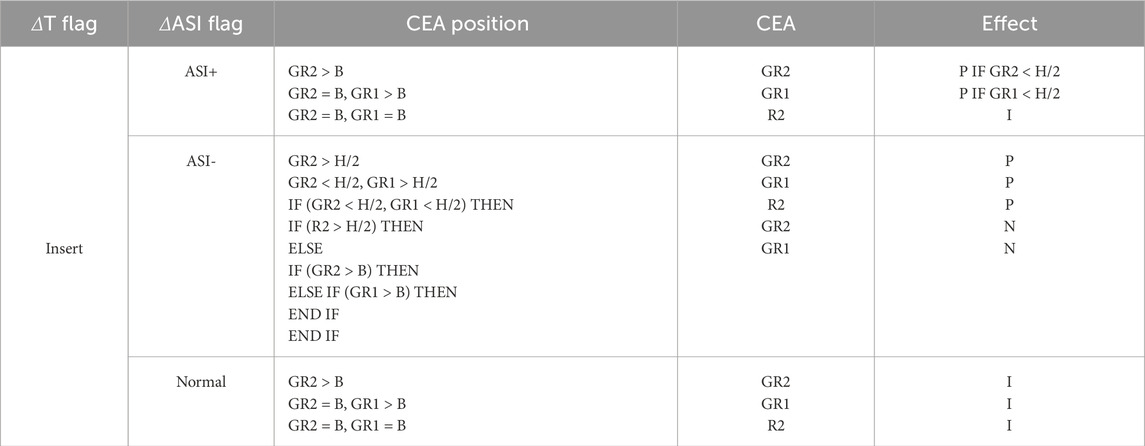
Table 7. CEA selection logic for insertion based on temperature and ASI flags.
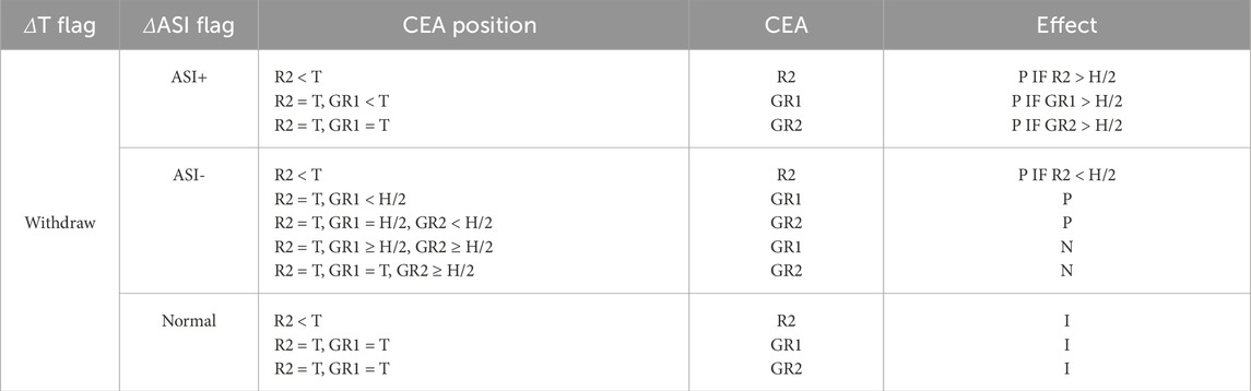
Table 8. CEA selection logic for withdrawal based on temperature and ASI flags.
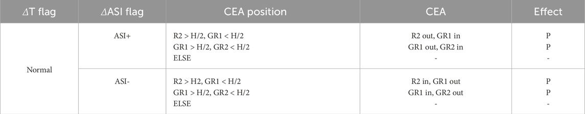
Table 9. CEA selection logic for ASI-only adjustment when temperature control is not required.
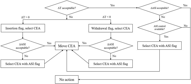
Figure 13. Simplified flow chart of Mode-Y logic.
4 Simulation results and discussions
4.1 Computational tool
The analysis was carried out using the conventional two-step nodal method. The homogenized two-group cross-sections and discontinuity factors were generated using SERPENT2 continuous-energy Monte Carlo code with ENDF/B-VII.1 nuclear data library. Temperature-dependent branch calculations were performed to generate cross-section libraries that account for thermal-hydraulic feedback. The reflector cross-sections and discontinuity factors were obtained by using I-shape geometry transport calculation results. The whole-core simulations were performed using the in-house nodal diffusion code KANT, which is based on the well-known NEM-CMFD scheme. To simulate DLFO scenarios, the Mode-Y control logic was applied to the ATOM core. Within KANT, this logic dynamically interprets temperature and ASI flags to determine the direction and speed of CEA movements in real time.
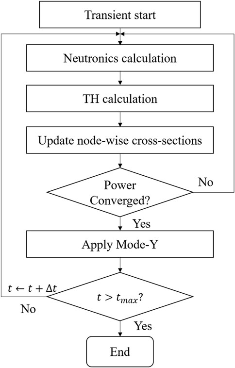
The time-dependent simulations are solved using transient NEM-CMFD scheme with a time step of 5 s. The nodal calculation is performed with a 2 × 2 node per assembly configuration. The convergence criteria are based on the norm 2 error of the neutron flux, with a convergence threshold of 1e-7 for the steady-state solution and 1e-5 for the transient solution. Each transient scenario required approximately 5 h of computation time using AMD Ryzen 9 5900X processor, with parallel computation utilizing 6 threads. Figure 14 provides a schematic overview of the calculation procedure applied during transient DLFO in KANT. To simplify the steam generator (SG) model while retaining realistic thermal feedback, it was assumed that the SG removes thermal energy precisely according to the power demand, thereby allowing the inlet coolant temperature to be linearly adjusted in response to the power variation. As a result, the model captures the temperature feedback behavior during slow transients such as daily load-follow operations without requiring detailed SG dynamics. This assumption removes secondary-side time lags and smoothing effects, resulting in more immediate feedback than typical of real SG systems to power changes and resulting in stronger, more immediate thermal feedback than would occur in a real plant where SG thermal inertia moderates the response. Nevertheless, the comparison with a more realistic model in (Khalefih, 2024) showed that the difference in inlet coolant temperature remained below 0.5 K. To reflect this behavior, an additional simulation was performed with a doubled temperature dead-band, representing reduced control tightness and delayed thermal feedback.
 t_{\text{max}} \); if yes, end, otherwise increment time and loop back." id="F14" loading="lazy">
Figure 14. Flow chart of transient calculation in KANT during DLFO simulation.
Pin-wise power distributions were reconstructed at each time step during the DLFO simulation using the form function method, and the resulting 3-D and 2-D pin peaking factors were evaluated in real time to monitor local power variations throughout the transient.
4.2 DLFO simulation
This section investigates DLFO performance of the original ATOM core at the equilibrium cycle using Mode-Y control logic. Simulations were conducted at three representative core burnup: BOC at 0 GWD/tU, MOC at 10 GWD/tU, and approximately 90% of EOC at 19 GWD/tU. It is assumed that the densities of xenon and samarium are at equilibrium. In addition, supplementary simulations using a doubled temperature dead-band are included at the end of Section 4.2 to assess the impact of reduced control tightness.
The DLFO scenario was deliberately designed to impose significant challenges on reactor power and axial power shape control. The reactor power was first reduced from 100% to 50% over a 3-h ramp-down period, followed by 12 h of sustained operation at 50% power. The power was then increased back to 100% within 3 h and maintained for 18 h. Subsequently, the reactor power was again ramped down from 100% to 50% over 3 h, held at 50% power for 9 h, and finally ramped up back to 100% within 3 h, with an additional 12-h full-power operation. This load-follow sequence involved very rapid power transitions and irregular power demand patterns, creating a much more challenging DLFO than typical load-follow conditions. The power demand scenario is illustrated in Figure 15.
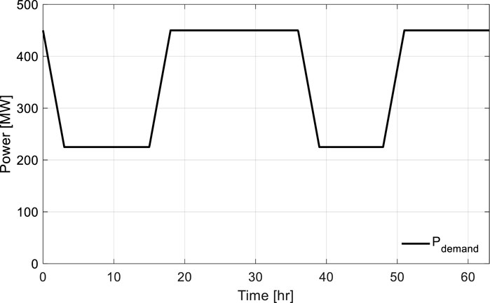
Figure 15. Power demand scenario.
Throughout the DLFO simulations, Mode-Y control logic dynamically adjusted CEA movements based solely on temperature and ASI stage flags. Notably, at the 90% EOC condition, an additional case was evaluated by intentionally disabling the ASI control function to examine its influence. This comparison allowed a direct assessment of the impact of ASI regulation during DLFO scenarios. Detailed results were analyzed for each burnup step using a set of six figures, covering core power, CEA position, xenon concentration, coolant temperature, ASI, and both nodal and pin-wise power peaking factors.
At the BOC condition, the ATOM core exhibited stable behavior under Mode-Y control. As shown in Figure 16, the reactor core power accurately followed the power demand profile, including rapid ramp-down, sustained low-power periods, and ramp-up transitions, with minimal delay or overshoot.
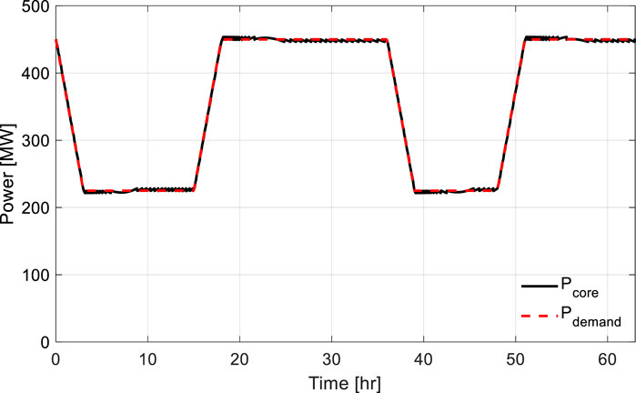
Figure 16. Reactor power variation during DLFO at BOC burnup condition.
Small fluctuations observed in the core power trace are a direct consequence of Mode-Y logic responding to temperature deviations beyond the defined dead-band. Whenever the average coolant temperature drifts outside the acceptable range, control rods are adjusted to return the temperature back into the dead-band, which in turn causes slight changes in the reactor power. This behavior reflects the designed feedback mechanism of Mode-Y and does not represent instability but rather the system’s dynamic response to maintain thermal balance.
Figure 17 illustrates the coordinated CEA movements required to accommodate reactivity changes during rapid power variations. The CEA positions are expressed as absolute vertical heights measured from the active core bottom, where 0 cm corresponds to the lower boundary of the active core and 200 cm to the top boundary.
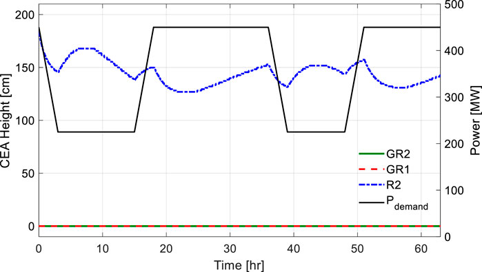
Figure 17. CEA movement during DLFO at BOC burnup condition.
Figure 18 illustrates how xenon concentration evolved in response to power variations. While the concentration exhibited noticeable fluctuations during power transients, the resulting reactivity effects were successfully compensated through combined CEA movements and inlet coolant temperature adjustments, demonstrating the robustness of Mode-Y control logic. Coolant temperatures, including inlet, average, and outlet values, were maintained within the acceptable dead-band, as shown in Figure 19.

Figure 18. Xenon concentration variation during DLFO at BOC burnup condition.
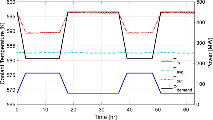
Figure 19. Coolant temperature variation during DLFO during BOC burnup condition.
The ASI behavior during BOC, shown in Figure 20, begins at approximately 0.05, initially decreases to around −0.01 during the first low-power period, and then rises sharply to a peak of approximately 0.17 during the subsequent power recovery. As the reactor enters the second low-power phase, the ASI drops back towards 0, followed by another increase to about 0.15 after the second power ramp-up. This oscillatory ASI behavior reflects the complex axial power distribution during repeated LFOs. The overall upward trend in ASI is primarily attributed to the initial configuration of control banks. At BOC, all gray banks (GR2 and GR1) are fully inserted to compensate for initial excess reactivity, necessitating the use of the regulating bank R2 to respond to power changes. As confirmed by the corresponding CEA position plot (Figure 17), the R2 bank remains in the upper region of the core, leading to an upward shift in the axial power distribution and the observed increases in ASI during power ascension.
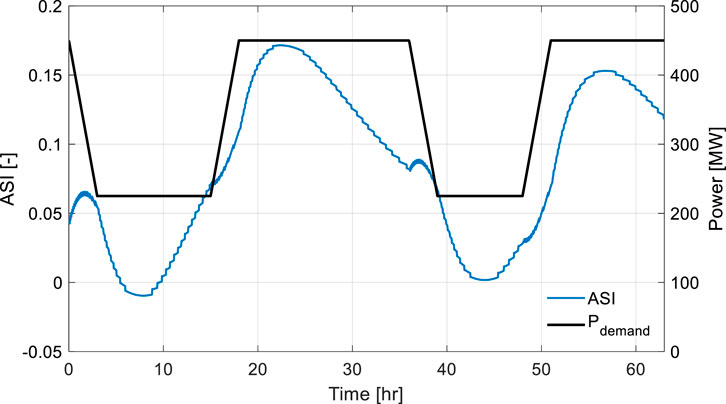
Figure 20. ASI variation during DLFO at BOC burnup condition.
Additionally, the tendency of the ASI to return closer to 0 during low-power periods can also be explained by thermohydraulic feedback. At lower power, the temperature difference between the coolant inlet and outlet becomes smaller, reducing the overall temperature gradient across the core. Given that the ATOM core exhibits a strongly negative MTC, the diminished temperature gradient results in weaker axial power imbalances, naturally bringing the ASI closer to 0 during low-power holding phases.
Figure 21 presents the time evolution of various peaking factors. When the notation “-Pin” is appended, it denotes pin-level results, whereas the notaion ‘-Nodal’ indicates sub-assembly nodal results. The radial peaking factor at the sub-assembly level remains nearly constant. In contrast, the radial pin peaking factor exhibits fluctuations that correspond to CEA movements, reflecting localized power perturbations near control rod regions. The axial peaking factor also shows expected variations as control rods are inserted and withdrawn during DLFO. The 3-D peaking factor remains around 1.8, while the reconstructed 3-D pin peaking factor peaks at approximately 1.9. These values are significantly below the 3-D peaking limit of 2.43 typically applied to large PWRs, indicating that the ATOM core maintains a substantial margin with respect to local power density constraints, even under frequent and asymmetric power changes (Mahmoud and Diab, 2020).
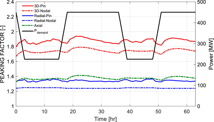
Figure 21. Peaking factor variation during DLFO at BOC burnup condition.
At the MOC condition, the ATOM core continued to exhibit robust load-follow capability under Mode-Y control logic. As shown in Figure 22, the core power successfully followed the prescribed demand curve, including rapid transitions and prolonged low-power states.
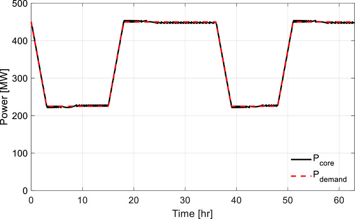
Figure 22. Reactor power variation during DLFO at MOC burnup condition.
The CEA movement patterns during this period are depicted in Figure 23. Unlike BOC, where regulating bank R2 was used extensively, R2 remained fully withdrawn for the majority of the MOC scenario. However, it was briefly inserted around the 38-h mark, not for reactivity compensation, but as part of the ASI control logic to counteract axial power shape deviation.
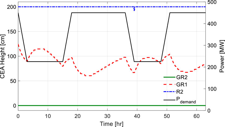
Figure 23. CEA movement during DLFO at MOC burnup condition.
Throughout the rest of the scenario, gray bank GR2 was fully inserted, and the primary control action was achieved solely through the movement of GR1. Notably, GR1 is composed of Mn with a lower neutron absorption cross-section compared to R2, resulting in smaller reactivity and axial power shape impact per unit insertion. This control strategy effectively minimized axial power skewness during DLFO.
The xenon concentration trend presented in Figure 24 shows natural fluctuations in response to power changes, similar to the behavior observed at BOC. The reactivity impacts from its buildup and decay were effectively compensated by timely CEA adjustments and coolant temperature strategy. Also, coolant temperatures throughout the scenario are illustrated in Figure 25, where the average temperature remains tightly bounded within the temperature dead-band.
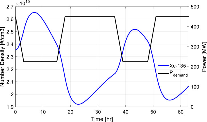
Figure 24. Xenon concentration variation during DLFO at MOC burnup condition.
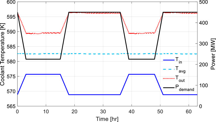
Figure 25. Coolant temperature variation during DLFO during MOC burnup condition.
The ASI behavior shown in Figure 26 reflects this operational characteristic. The ASI starts at approximately 0.07, increases to a maximum of 0.11, and decreases to a minimum of −0.04. These values indicate a significantly smaller amplitude of ASI variation compared to BOC, where regulating rods located in the upper core region (e.g., R2) were used. The use of GR1 alone limited the axial power distortion during DLFO.
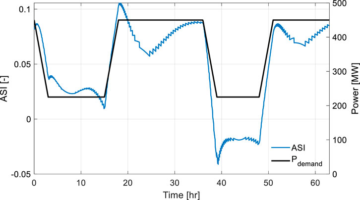
Figure 26. ASI variation during DLFO at MOC burnup condition.
The evolution of peaking factors is shown in Figure 27. The nodal radial peaking factor remained almost steady, while the pin-wise radial peaking factor exhibited slight fluctuations in response to GR1 motion. The axial peaking factor shows noticeable but controlled fluctuations, which is expected due to the changes in CEA positions during DLFO. The 3-D nodal peaking factor consistently remained below 1.7, and the reconstructed 3-D pin peaking factor did not exceed 2.0 at any point during the scenario.
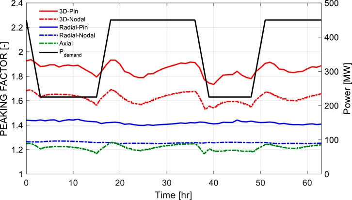
Figure 27. Peaking factor variation during DLFO at MOC burnup condition.
At the 90% EOC condition, the ATOM core was evaluated under the same DLFO scenario. As shown in Figure 28, the core power closely followed the frequent power variation pattern with high fidelity. Minor power deviations reflect reactivity compensation actions triggered by average coolant temperature deviations exceeding the Mode-Y dead-band.
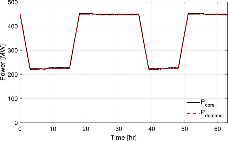
Figure 28. Reactor power variation during DLFO at EOC burnup condition.
Figure 29 displays the CEA movement during the DLFO scenario. At 90% EOC condition, the CSBA was nearly depleted; however, since the nuclear fuel had not yet been fully burned, the insertion of gray banks GR2 and GR1 was still necessary to compensate for the remaining excess reactivity. This behavior is also consistent with the reactivity trend observed in the previous study (Wijaya et al., 2024). GR2 remains fully inserted throughout the transient, while GR1 operates primarily in the lower core region. The regulating bank R2 is periodically inserted in the upper region to tune the average coolant temperature and provide ASI control during DLFO.
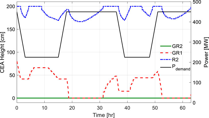
Figure 29. CEA movement during DLFO at EOC burnup condition.
Notably, R2 insertion events observed around the 8-h and 38-h marks are not for reactivity compensation but are primarily driven by the need to reduce ASI deviation. In both cases, GR1 remains unaltered while R2 is selectively inserted to reduce ASI deviations during low-power holding periods.
The xenon concentration trend in Figure 30 follows a similar pattern as those observed at BOC and MOC. These variations were effectively managed by the Mode-Y logic. Coolant temperature behavior is shown in Figure 31, where the average temperature remains well-regulated within the control range.
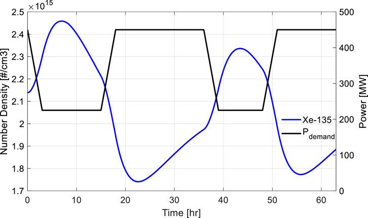
Figure 30. Xenon concentration variation during DLFO at MOC burnup condition.
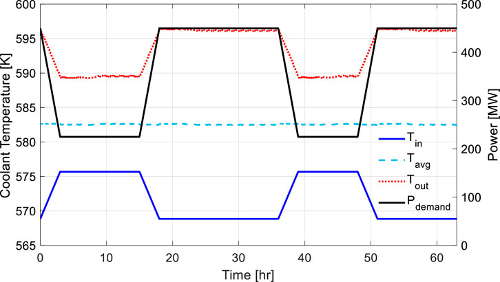
Figure 31. Coolant temperature variation during DLFO during EOC burnup condition.
The ASI evolution at 90% EOC is presented in Figure 32. The ASI begins at approximately 0.07 and drops to −0.11 as reactor power decreases during the first ramp-down. It then rises to around 0.05 while the core is maintained at full power. During the second low-power period, ASI again decreases, reaching approximately −0.12, before recovering to around 0.06 during the final return to full power. These variations remain within safe limits and demonstrate that Mode-Y effectively maintains axial power shape.
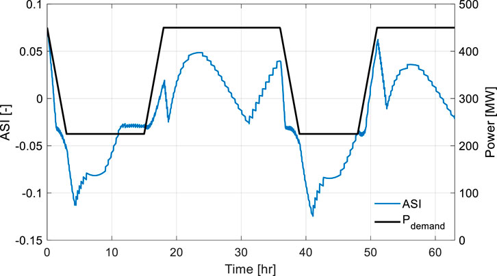
Figure 32. ASI variation during DLFO at EOC burnup condition.
To highlight the impact of ASI control, a comparative case without ASI control was also simulated at 90% EOC condition. As shown in Figure 33, the ASI dropped as low as −0.155 twice during the scenario, showing more severe axial power distortion. This excessive top-skewed shape results from the absence of R2 movement; instead, the control logic relied solely on GR1 for power regulation. This comparison strongly supports the effectiveness of ASI control in Mode-Y.
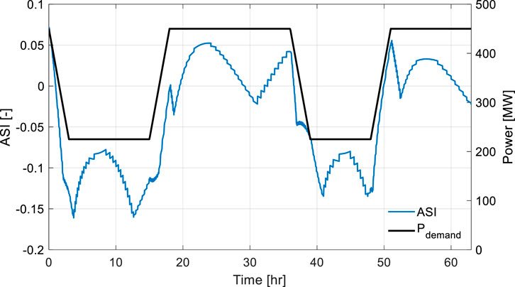
Figure 33. ASI variation during DLFO without ASI control at EOC burnup condition.
Figure 34 illustrates the peaking factor trends. The axial peaking factor remained consistently below 1.3 throughout DLFO. While the 3-D peaking factor was slightly higher than those observed at BOC and MOC, it remained below 1.9 at the nodal level. The 3-D pin peaking factor showed a small rise, slightly exceeding 1.9, but crucially remained below 2.0. These values confirm that the ATOM core preserves sufficient thermal margin and maintains safe power distribution even under high-burnup and repeated load-follow operations.
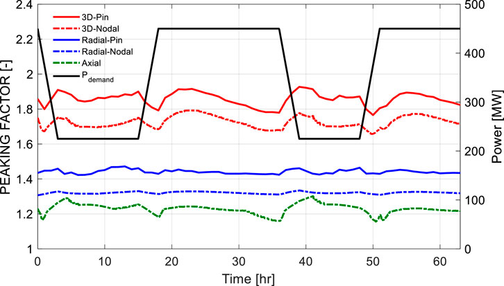
Figure 34. Peaking factor variation during DLFO at EOC burnup condition.
In addition, sensitivity tests were performed to assess the robustness of the Mode-Y control logic by doubling the temperature dead-band from ±0.3K to ±0.6K. The simulation results—including reactor power, CEA positions, ASI, and peaking factors—are presented separately for BOC (Figures 35–38), MOC (Figures 39–42), and EOC (Figures 43–46) conditions. At each burnup step, the wider dead-band resulted in slight deviations of reactor power from the demand, yet the load-following performance remained effective. Moreover, ASI trends, CEA positions, and peaking factors exhibited behaviors nearly identical to the baseline scenarios across all burnup conditions, highlighting the robustness and stability of Mode-Y control logic under relaxed control constraints. Importantly, the magnitude of ASI deviations and the maximum 3-D pin peaking factors remained well within acceptable limits.

Figure 35. Reactor power variation during DLFO at BOC using wider temperature dead-band.
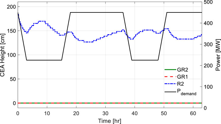
Figure 36. CEA movement during DLFO at BOC using wider temperature dead-band.
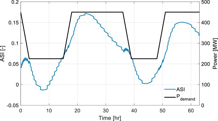
Figure 37. ASI variation during DLFO at BOC using wider temperature dead-band.
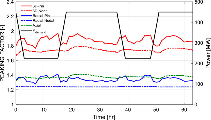
Figure 38. Peaking factor variation during DLFO at BOC using wider temperature dead-band.
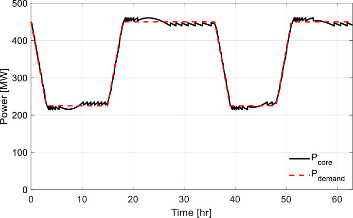
Figure 39. Reactor power variation during DLFO at MOC using wider temperature dead-band.
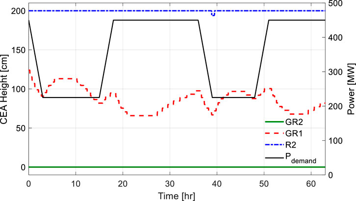
Figure 40. CEA movement during DLFO at MOC using wider temperature dead-band.
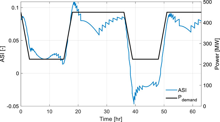
Figure 41. ASI variation during DLFO at MOC using wider temperature dead-band.
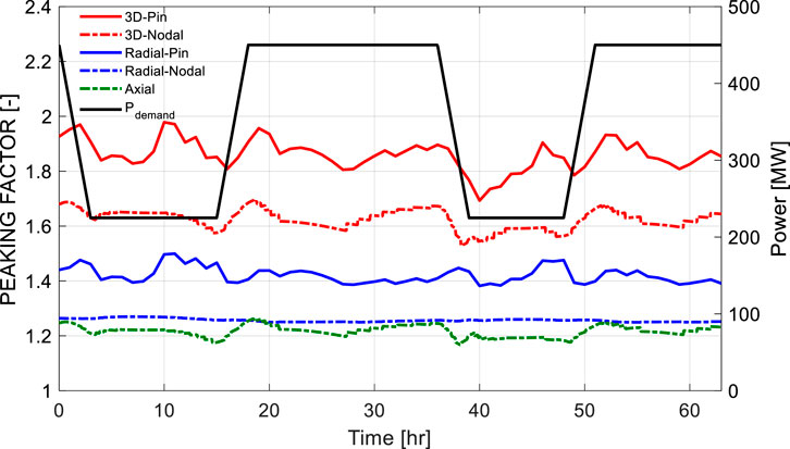
Figure 42. Peaking factor variation during DLFO at MOC using wider temperature dead-band.
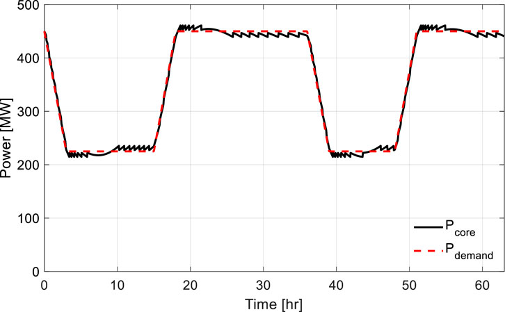
Figure 43. Reactor power variation during DLFO at EOC using wider temperature dead-band.
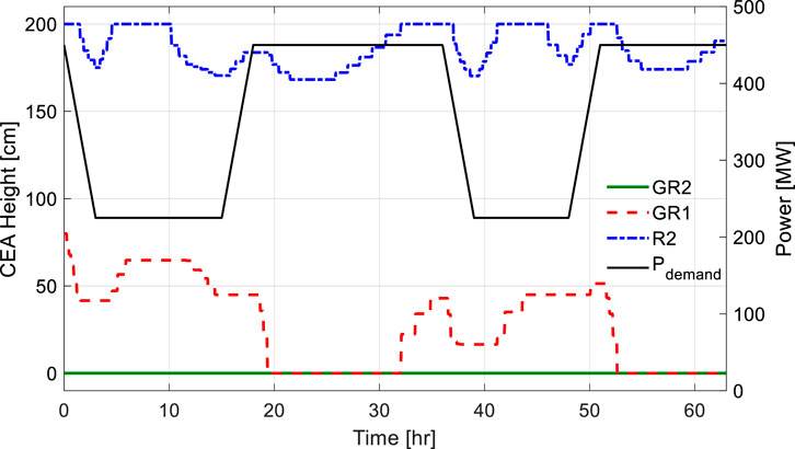
Figure 44. CEA movement during DLFO at EOC using wider temperature dead-band.
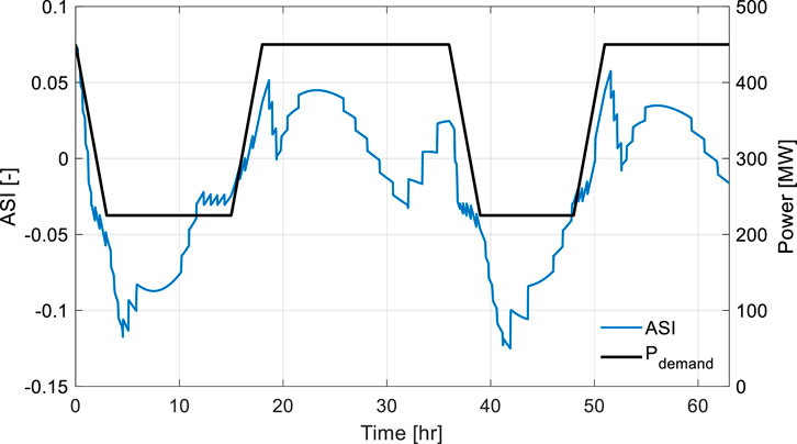
Figure 45. ASI variation during DLFO at EOC using wider temperature dead-band.

Figure 46. Peaking factor variation during DLFO at EOC using wider temperature dead-band.
5 Conclusion and future work
This study analyzed the performance of Mode-Y control logic applied to the ATOM small modular reactor under DLFO scenarios at the BOC, MOC, and 90% EOC burnup conditions. Results confirm that combined utilization of the ATOM core’s features-particularly CSBA and Truly-Optimized PWR lattice configuration-alongside Mode-Y logic, enables highly effective DLFO in SBF environments. The presence of CSBA significantly reduces the reactivity swing throughout the cycle, providing stable excess reactivity conditions essential for effective load-follow operations. Moreover, precise coolant temperature control and ASI management were successfully achieved even under rapid and irregular power maneuvering, demonstrating the robustness of the Mode-Y control approach.
Effective utilization of gray banks (GR2 and GR1) and the regulating bank (R2) successfully mitigated axial power shape deviations. Comparative analyses demonstrated that Mode-Y’s ASI control logic significantly improved axial stability compared to scenarios without ASI control, underscoring its critical role in maintaining stable axial power distribution.
Additionally, the study consistently confirmed adequate thermal safety margins across different burnup conditions. Axial peaking factors remained consistently below 1.3, nodal 3-D peaking factors did not exceed 1.9, and pin-wise 3-D peaking factor remained comfortably below 2.0. These values confirm robust safety margins, even during irregular and frequent power ramp up and down.
To evaluate the robustness of Mode-Y under relaxed control conditions, additional simulations were conducted with a doubled temperature dead-band. The resulting power tracking performance remained satisfactory across all burnup stages, and the ASI, CEA positions, and peaking factors showed trends consistent with the baseline results. Even with less frequent rod motion, both ASI variations and 3-D pin peaking factors were maintained within acceptable ranges, validating the Mode-Y logic’s stability margin.
Overall, this research demonstrates the successful synergy between the inherent features of CSBA-loaded ATOM core and Mode-Y control logic, effectively establishing robust load-follow capabilities across the entire reactor cycle.
In future research, further investigations will focus on extending Mode-Y’s application to frequency control scenarios, a critical operational requirement aimed at addressing short-term imbalances between electricity production and demand. Additionally, future studies will explore reactor startup behavior under various burnup conditions to confirm smooth and reliable startup capabilities of ATOM core and to provide comprehensive validation of Mode-Y control logic.
Data availability statement
The original contributions presented in the study are included in the article/supplementary material, further inquiries can be directed to the corresponding author.
Author contributions
YJ: Writing – original draft, Writing – review and editing. DC: Writing – review and editing. TO: Writing – review and editing. YK: Conceptualization, Supervision, Writing – review and editing.
Funding
The author(s) declare that financial support was received for the research and/or publication of this article. This research was supported by Korea Energy Technology Evaluation and Planning (KETEP) grant funded by the Korean Government (MTIE) (RS-2024-00439210) and National Research Foundation of Korea (NRF) grant funded by the Korea government (MSIT) (RS-2023-00260898).
Conflict of interest
The authors declare that the research was conducted in the absence of any commercial or financial relationships that could be construed as a potential conflict of interest.
Generative AI statement
The author(s) declare that no Generative AI was used in the creation of this manuscript.
Any alternative text (alt text) provided alongside figures in this article has been generated by Frontiers with the support of artificial intelligence and reasonable efforts have been made to ensure accuracy, including review by the authors wherever possible. If you identify any issues, please contact us.
Publisher’s note
All claims expressed in this article are solely those of the authors and do not necessarily represent those of their affiliated organizations, or those of the publisher, the editors and the reviewers. Any product that may be evaluated in this article, or claim that may be made by its manufacturer, is not guaranteed or endorsed by the publisher.
References
Abdelhameed, A. E., Nguyen, X. H., and Kim, Y. (2018). Feasibility of passive autonomous frequency control operation in a soluble-boron-free small PWR. Ann. Nucl. Energy 116, 319–333. doi:10.1016/j.anucene.2018.02.036
Cheng, Z. (2020). Safety analysis of a compact integral small light water reactor, ph.D. dissertation, dept. Nuclear science and engineering. Cambridge, MA, USA: Massachusetts Institute of Technology.
Dong, Z., Li, B., Li, J., Guo, Z., Huang, X., Zhang, Y., et al. (2021). Flexible control of nuclear cogeneration plants for balancing intermittent renewables. Energy 221, 119906. doi:10.1016/j.energy.2021.119906
Ilyas, M., and Aydogan, F. (2017). Steam generator performance improvements for integral small modular reactors. Nucl. Eng. Technol. 49 (8), 1669–1679. doi:10.1016/j.net.2017.08.011
International Atomic Energy Agency (2018). Small modular reactors: a new nuclear energy paradigm. Vienna: IAEA.
International Energy Forum (2021). “Small modular reactors: key considerations for deployment,” IEF Report.
Jenkins, J. D., Zhou, Z., Ponciroli, R., Vilim, R. B., Ganda, F., de Sisternes, F., et al. (2018). The benefits of nuclear flexibility in power system operations with renewable energy. Appl. Energy 222, 872–884. doi:10.1016/j.apenergy.2018.03.002
Jeong, Y. (2021). A study on multiphysics startup simulation of the soluble-boron-free ATOM system, M.S. thesis, dept. of nuclear and quantum eng., Korea Advanced institute of Science and Technology. Daejeon, South Korea: KAIST.
Jeong, Y., Wijaya, S., and Kim, Y. (2023). Load-follow simulation of a 540 MWth soluble-boron-free SMR using CSBA. Present. A. T. React. Phys. Asia (RPHA) Conf. Gyeongju, Korea, Oct. 24–26.
Khalefih, H. (2024). Development of sliding-mode xenon observer for load follow operations of APR1400 using Mode-K+ algorithm. Daejeon: Ph.D. dissertation, Korea Advanced Institute of Science and Technology KAIST.
Khalefih, H., and Kim, Y. (2024a). Load-follow operation in LEU+ loaded very-low soluble boron APR1400. Prog. Nucl. Energy 177, 105415. doi:10.1016/j.pnucene.2024.105415
Khalefih, H., and Kim, Y. (2024b). A study on xenon estimation during load-follow operation using sliding mode observer in APR1400 for a predictive soluble boron control. Arabian J. Sci. Eng. 50, 3491–3503. doi:10.1007/s13369-024-09620-3
Khalefih, H., Jeong, Y., and Kim, Y. (2023). Daily load-follow operation in LEU+-loaded APR1400 using Mode-K+ control logic. Int. J. Energy Res. 2023, 1–21. doi:10.1155/2023/1853535
Khalefih, H., Jeong, Y., and Kim, Y. (2025). Daily load-follow operation in APR1400 without soluble boron adjustment using the Mode-K+. Nucl. Sci. Eng. 1, 1–21. doi:10.1080/00295639.2025.2475414
Kim, Y. H., and Park, M. G. (2000). “Evaluation of load follow performance of Korean next generation reactor (KNGR),” in 2000 ANS international topical meeting on advances in reactor physics and mathematics and computation into the next millennium, PHYSOR 2000 (American Nuclear Society).
Kim, Y. H., Park, M. G., Kim, Y. B., and Choi, Y. S. (1999). “Load follow performance of KNGR using an extended mode-K control logic,” in Spring meeting of the Korean nuclear society.
Leppänen, J., Pusa, M., Viitanen, T., Valtavirta, V., and Kaltiaisenaho, T. (2015). The serpent Monte carlo code: status, development and applications in 2013. Ann. Nucl. Energy 82, 142–150. doi:10.1016/j.anucene.2014.08.024
Locatelli, G., Bingham, C., and Mancini, M. (2014). Small modular reactors: a comprehensive overview of their economics and strategic aspects. Prog. Nucl. Energy 73, 75–85. doi:10.1016/j.pnucene.2014.01.010
Mahmoud, A. E. R., and Diab, A. (2020). A systems engineering approach to multi-physics load follow simulation of the Korean APR1400 nuclear power plant. J. Korean Soc. Syst. Eng. 16 (2), 1–15.
Mignacca, B., and Locatelli, G. (2020). Economics and finance of Small Modular reactors: a systematic review and research agenda. Renew. Sustain. Energy Rev. 118, 109519. doi:10.1016/j.rser.2019.109519
Nguyen, X. H., and Kim, Y. H. (2021). Truly-optimized PWR lattice for innovative soluble-boron-free small modular reactor. Sci. Rep. 11, 12891. doi:10.1038/s41598-021-92350-5
Nguyen, X. H., Kim, C. H., and Kim, Y. H. (2019). An advanced core design for a soluble-boron-free small modular reactor ATOM with centrally-shielded burnable absorber. Nucl. Eng. Technol. 51 (2), 369–376. doi:10.1016/j.net.2018.10.016
OECD/NEA (2021). “Technical and economic aspects of load following with nuclear power plants,” in Nuclear development. Paris: OECD Publishing. doi:10.1787/29e7df00-en
Oh, T., Jeong, Y., Khalefih, H., and Kim, Y. (2023). Development and validation of multiphysics PWR core simulator KANT. Nucl. Eng. Technol. 55 (6), 2230–2245. doi:10.1016/j.net.2023.02.025
U.S. Nuclear Regulatory Commission (NRC) (2011). Chapter 14: normal operating limits. 0520 - R325C. Available online at: https://www.nrc.gov/docs/ML1125/ML11251A047.pdf.
Wang, L., Wei, X., Zhao, F., and Fu, X. (2014). Modification and analysis of load follow control without boron adjustment for CPR1000. Ann. Nucl. Energy 70, 317–328. doi:10.1016/j.anucene.2013.12.001
Wijaya, S., Nguyen, X. H., Jeong, Y., and Kim, Y. H. (2024). Multi-batch core design study for innovative small modular reactor based on centrally-shielded burnable absorber. Nucl. Eng. Technol. 56 (2), 907–915. doi:10.1016/j.net.2023.11.007
Keywords: ATOM, daily load-follow operation, soluble boron-free, Mode-Y, CSBA
Citation: Jeong Y, Choi D, Oh T and Kim Y (2025) Load-follow operation capability of soluble boron-free small modular reactor ATOM. Front. Energy Res. 13:1639569. doi: 10.3389/fenrg.2025.1639569
Received: 02 June 2025; Accepted: 04 September 2025;
Published: 02 October 2025.
Edited by:
Shoaib Usman, Missouri University of Science and Technology, United StatesReviewed by:
Shripad T. Revankar, Purdue University, United StatesFarooq Ahmad, Missouri University of Science and Technology, United States
Copyright © 2025 Jeong, Choi, Oh and Kim. This is an open-access article distributed under the terms of the Creative Commons Attribution License (CC BY). The use, distribution or reproduction in other forums is permitted, provided the original author(s) and the copyright owner(s) are credited and that the original publication in this journal is cited, in accordance with accepted academic practice. No use, distribution or reproduction is permitted which does not comply with these terms.
*Correspondence: Yonghee Kim, eW9uZ2hlZWtpbUBrYWlzdC5hYy5rcg==