 Yongqing Lai1
 Yang Yang
- 1PowerChina Huadong Engineering Corporation Limited, Hangzhou, Zhejiang, China
- 2Faculty of Maritime and Transportation, Ningbo University, Ningbo, Zhejiang, China
As the size and installed capacity of the wind turbines continue to evolve globally, the aerodynamics and fatigue damage on the support structures are experienced a corresponding increasing trend. Consequently, the significance of improving the structural safety of the wind turbines has become incredibly critical. To address aforementioned challenges, the tower-top acceleration feedback control technique has emerged as a promising solution to improve stability and long-term operational reliability by mitigating vibrations, reducing fatigue damage, and enhancing overall structural safety. This study aims to comprehensively investigate the influence of tower-top acceleration feedback control on the operational characteristics and structural responses of the IEA 15 MW wind turbine under complex environmental loadings. The key performance indicators involving the responses of the tower and pile foundation have been systematically analyzed with various damping gain parameters. In addition, the fatigue damage analysis has been conducted under 4 m/s to 25 m/s wind speed conditions. The obtained results demonstrate that the tower-top acceleration gain control can significantly reduce the tower-top displacement, acceleration, and pile foundation loads under wind speeds ranging from 6 m/s to 11 m/s and some of severe conditions. Notably, the most significant reduction in maximum, average and standard deviation of the mudline bending moment of the wind turbine is exhibited by as much as 15.27%, 0.83%, and 24.46%, respectively, under a 6 m/s wind speed scenario. However, the demand for gain control is relatively minimal, where the wind turbine reaches its rated rotor speed with the most intense aerodynamics. A similar trend can be found in the fatigue damage at the tower-base, pile-top, sea water level (SWL), and mudline of the support structure of the wind turbine. It can be significantly mitigated due to appropriate gain control under mild and severe environmental scenarios. These findings prove that well-implemented tower-top acceleration feedback control system not only improves the aerodynamic performance of the monopile-type wind turbine, but also enhances the structural safety, thereby providing a reliable technical support for the continuous development of the large-capacity offshore wind turbines (OWTs).
1 Introduction
With the increasing requirement of the renewable energy, offshore wind has attracted global attention due to its advantages of being clean, efficient and abundant resources. In addition, the wind turbines have developed fast and towards larger capacities. The significant argument in the individual capacity of wind turbines contributes to higher energy utilization efficiency, however, it brings challenges in the complex structural responses and heightened fatigue damage at the same time. Moreover, the complicated environmental loadings composed of wind, waves, currents, sea ice and seismic activities can also introduce more intense coupling effects of the wind turbines. Therefore, the structural loads on the tower-top, pile foundation, and blades of the wind turbine are experiencing significant variability.
In addition, the key components of the wind turbine, especially the tower, experience significant vibrations due to larger variations in wind speeds. These vibrations can dramatically affect the operating stability, structural lifespan, and the capacity of output power. To address these research challenges, the implement of tower-top acceleration feedback control technique can effectively mitigate or suppress unnecessary vibrations based on real-time monitoring and feedback control of the tower-top interactions, thereby enhancing the operational reliability and structural safety of the wind turbines. Specifically, the pitch-control and rotor-speed control systems are designed for mitigating accumulated fatigue damage of the wind turbine. So as to ensure the structural safety, stable operation, and efficient output power, it is of great significance to investigate the influence of tower-top acceleration feedback control on the dynamic behavior and fatigue load of the wind turbine under complex environmental loadings.
Most current studies have focused on the controller design to enhance the performance of the wind turbine, improving the key performance indicators, such as power production capability, fatigue load, and dynamic responses. For instance, Pascu et al. (2017) proposed a tower fore-aft damping control methodology to reduce the fatigue load at the support structure of the wind turbine by up to 3% when the natural frequency of tower deviates from the nominal value. Zhang et al. (2014) developed an active control method using generator torques with feedback to mitigate the tower interaction based on gear-driven and direct-driven wind turbines. It was found that the feedback control made little influence on the smoothness of the output power from the generator. Kumar et al. (2016) developed a methodology to apply individual pitch control based on the tower-top strain gauge feedback taking place of blade-root strain gauge feedback. The obtained results showed that the proposed method could effectively mitigate the fatigue load by up to 2.5% of the wind turbine compared to the conventional methodologies. Mohammadi et al. (2014) proposed an adaptive controller to suppress the tower vibration under various environmental loadings based on the characteristics of an internal model in an error feedback loop. FAST, TurbSim, AeroDyn, and Simulink were integrated for simulation research. Nam et al. (2013) compared the effect of linear quadratic regulation on the mechanical load mitigation of the wind turbine to that when using a PI controller. Schlipf et al. (2014) compared a nonlinear and linear model predictive controller to a baseline controller. It was found that those controllers both could improve the dynamic behavior, while the nonlinear model predictive controller performed better in comparison with the linear controller under the rated speed scenario. Perrone (2015) conducted the simulation which were iterated for three control strategies involving baseline control, traditional tower control, and advanced tower control of the 5 MW wind turbine under two combined wind-sea conditions. It was found that the proposed technique could mitigate fatigue load of the wind turbine without severely impairing pitch actuators. In addition, the results revealed that the reduction of tower load was correlated with the online time-frequency simulation of tower vibrations. Ren et al. (2015) investigated the impact of the tower vibration including the fore-aft and side to side of the wind turbine using the Passivity-based Control (PBC) method. It could effectively reduce the tower vibration using the offshore Permanent Magnet Synchronous Generator. It demonstrated that the PBC methodology can not only mitigate the fatigue damage of tower, but enhancing the stability of output power for the generator compared to the traditional tower controller. Jassmann et al. (2016) developed a model predictive controller (MPC) to enhance the output power with limited mechanical loads of a commercial 3 MW wind turbine. The obtained data presented that the output power within a limit of 4% under an extreme operation gust, compared to 8% before. Meanwhile, the bending moment at the tower-base of the wind turbine could be reduced by approximately 15%.
In addition, Brodersen et al. (2017) proposed an active tuned mass damper (TMD) for damping of tower vibrations of the fixed OWTs, where the additional actuator force was operated based on feedback according to the relative velocity of the damper mass and tower displacement. Lio et al. (2018) developed an individual pitch-based tower controller according to the rotor speed regulation loop. The results showed that the proposed individual-pitch-based tower controller could achieve a similar performance compared to the collective-pitch-based methodology without negligible influence based on the nominal output power of the wind turbine. Yang and Li (2018) proposed an active control method to improve the stability of platform roll motion of the wind turbine operating in the downwind direction based on minor revise of the tail furling module in aerodynamics, structures, fatigue, and turbulence. It was found that the variance of roll motion angle presents mitigation by up to 73%–95%, while the fatigue damage for the side-side of tower-base bending moment was able to decreased by 20%–61%. Cetrini et al. (2019) developed a robust control methodology by evaluating the fatigue load of wind turbines. The virtual sensor was used to estimate the fatigue damage, meanwhile the blade pitch and generator torque allows to enhance the output power and load mitigation the most significantly. A controller with additional proportional gain was proposed by Lenfest et al. (2020) to improve the dynamic behavior and reduce the fatigue load of the wind turbine. Wu and Wang (2022) developed an active and passive combination vibration control system (HMD) for the barge-type wind turbine by integrating a longitudinal TMD with limited stroke. The influence of TMD and HMD on the hydrodynamic responses of the wind turbine has been investigated under combined wind and wave scenarios. It demonstrated that the vibration mitigation impact of the HMD integrated control was effectively enhanced with the constraints of TMD stroke. Grant et al. (2022) studied the interdependencies of a parallel floating feedback controller and platform control based on OpenFAST. The results demonstrated that the floating feedback control and static floater can be adopted at the same time to mitigate the structural loads and platform motions. Long et al. (2023) established a model considering the aero-servo-structure coupling effects of the wind turbine with feedback control force based on the virtual TMD algorithm. It was found that the active control was able to suppress the interaction of wind turbines under various environmental loadings. The proposed controller could augment the mitigation impact of wind turbine behavior with minor stroke and control force under operating modes. Pamososuryo et al. (2024) proposed a modulation-demodulation control (MDC) strategy to mitigate the side-side tower load based on the variable speed of wind turbine. The periodic loading and natural frequency excitation in the side-side tower motion can be effectively reduced using that diagonal linear time-invariant controller. Wang et al. (2024) implemented a real-time blade pitch and generator torque control to study the impacts of feedback and thrust maximum shaving. The influence of hull-based TMD on mitigating the fatigue load of the wind turbine has also been investigated. Chen et al. (2024) proposed an integrated controller by combining the maximum power point tracking (MPPT) torque control and feedback-feedforward blade pitch control, which could effectively mitigate the fatigue damage and enhance output power of the wind turbine. The aero-hydro-servo-elastic-soil interactions of the wind turbine was comprehensively considered. The results showed that the mudline bending moment and tower-top displacement of the wind turbine under relatively higher wind speed scenarios can be reduced by close to 10% due to the hybrid control strategy.
To recapitulate, there has been a lack of research on tower-top acceleration feedback control and parametric studies so far. In addition, the influence of environmental loadings n the effectiveness of tower-top feedback gain control has not been comprehensively investigated. The effect of the feedback control on the dynamic performance, particularly the fatigue damage in the long-term span of the wind turbine is relatively scarce. To address the aforementioned drawbacks, this research will evaluate the influence of feedback control in the dynamic response and fatigue damage of the wind turbine using the open-source software OpenFAST under complicated environmental loadings.
The remaining sections of this study are organized as follows: Section 2 provides an overview of the fundamental theories related to the tower-top acceleration feedback control. Section 3 describes the environmental load cases (LCs) and outlines the IEA 15 MW wind turbine adopted in this research. Section 4 explores the dynamic behavior and fatigue damage of the wind turbine with respect to the feedback control. Section 5 concludes with a summary of the main findings of this study.
2 Description of the tower-top acceleration feedback control
2.1 Introduction of blade pitch angle controller
The control system used to achieve the adjustment of rotor speed and blade pitch of the wind turbine is composed of two parts, including the torque-speed control system and the blade pitch angle control system. It can make sure that the largest utilization efficiency can be achieved for the wind turbine under relatively lower wind speeds, meanwhile stable output rated power at higher wind speeds. The former sub-system is primarily focused on the scenarios below the rated wind speed, adjusting the rotor speed to maximize the aerodynamic efficiency to enhance the utilization of wind energy. The latter sub-system is designed for the relatively severe conditions. It can effectively adjust the blade pitch angle to mitigate the aerodynamic efficiency, ensuring the structural safety of the wind turbine at rated output power.
The blade pitch angle controller is activated to decrease the utilization efficiency of the wind energy and keep the rated output power when the rotor speed of wind turbine exceeds the rated speed. It can significantly protect the structural safety of the wind turbine and generator, avoiding overload scenarios. Therefore, a proportional-integral (PI) gain controller is adopted to simulate the variation of the blade pitch angle and rotor speed at the same time (Hwas and Katebi, 2012).
The drivetrain system composed of the rotor main shaft, gear box, and generator high-speed shaft is considered as a single-degree-of-freedom (DOF) system, where the DOF is equivalent to the orientation of the rotational axis. The equation of motion for the free vibrations of the drivetrain system is presented in the Equation 1 below:
wherein,
The generator torque is inversely proportional to the rotational speed with respect to the pitch control, therefore
where
Similarly, the wind turbine torque is negatively correlated with the rotational speed, which can be expressed in Equation 3 below:
where P is the actual output power of wind turbine,
Perform a first-order Taylor expansion in Equation 4:
wherein
where
Moreover, the dynamic model of the drivetrain of the rotational speed variation is presented in Equation 6:
The rotor speed variation is the solution of the second-order dynamic system of the PID controller. The natural frequency
The corresponding proportional gain
2.2 Basic theory of tower-top acceleration feedback control
The traditional methodology for improvement of the tower damping of fixed wind turbines is integrate an additional blade-pitch control loop for rotor-speed regulation that requires a tower-top acceleration feedback control. The integrate of the control loop is used to increase the aerodynamic rotor thrust with revise for the blade-pitch angle using the tower-top acceleration methodology. The variations in the rotor thrust with full-span rotor-collective blade-pitch angles would be considered to investigate the influence of blade-pitch angle on the platform-pitch damping coefficient, which can be calculated in Equation 9 as follows (Jonkman, 2008):
where in,
On top of that, as can be seen in Equation 11 the integrate of the control loop is able to adjust the effective damping parameter as follows, the effective mass and stiffness parameters would be kept unchanged with the addition of the control loop:
If the relationship between the rotor thrust sensitivity, pitch angle, and the rotor is known, the pitch angle damping ratio of the wind turbine platform can be effectively enhanced using a reasonable control gain. The following Equation 12 can be developed based on the existing model:
3 Introduction to IEA 15 MW wind turbine
A 15 MW direct-drive prototype wind turbine was designed by National Renewable Energy Laboratory (NREL) of the United States collaborated with the Technical University of Denmark (DTU) in 2020, namely, the IEA 15 MW wind turbine, as shown in Figure 1.
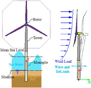
Figure 1. Schema of IEA 15 MW monopile OWT.
It is a monopile-type wind turbine. The rotor diameter of the wind turbine is represented 240 m, with a hub height and diameter of 150 m and 7.94 m, respectively. The rated power of the wind turbine can be achieved by 15 MW under the rated wind speed of 10.59 m/s. The blade mass and diameter are respectively 65 t and 240 m. It has been the largest wind turbine publicly used for academic studies so far. The main design parameters of the IEA 15 MW wind turbine are presented in Table 1.
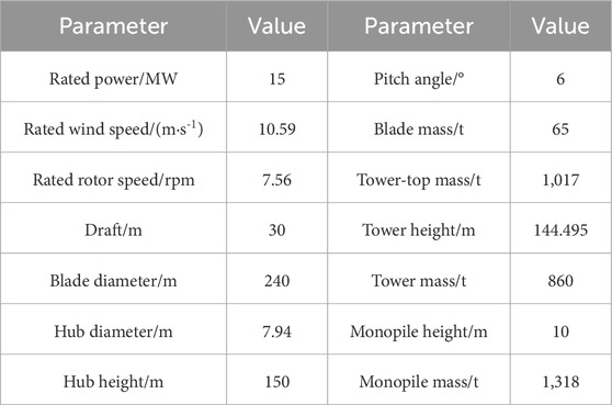
Table 1. Main parameters of IEA 15 MW OWT.
This study is based on the precise data of the IEA 15 MW reference wind turbine released by the International Energy Agency (IEA). The 15 MW OWT is developed based on the open-source software OpenFAST to provide a reliable and precise simulation model for further research involving the effect of tower-top acceleration feedback control on the structural response and fatigue load of the wind turbine structures.
4 Results and discussions
4.1 Load cases
Table 2 presents the wind speed and corresponding met-ocean data of the examined LCs adjacent to the coast of northern Scotland. The turbulent wind is generated using the Kaimal spectrum, while the irregular waves are modeled based on the JONSWAP spectrum. In addition, the overall simulation time and each time step is set to 1,000 s and 0.005 s, respectively. Due to transient behavior during wind turbine start-up process, results of previous 400 s are neglected. Moreover, the baseline KI value without feedback control of the wind turbine is −1. Two KI values of 0.02 and 0.1 are adopted in this research to investigate the key performance indicators involving tower-top displacement, tower-top acceleration, and mudline bending moment, as well as the fatigue damage of the wind turbine and compared to the results of baseline.
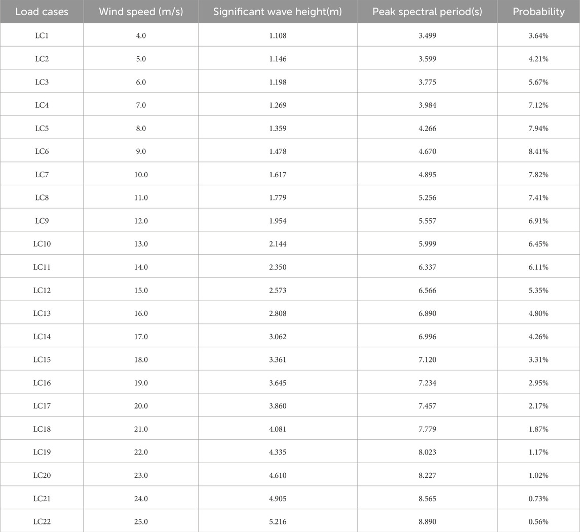
Table 2. The examined environmental conditions (Yang et al., 2020).
Moreover, so as to comprehensively investigate the effect of feedback control of the tower-top acceleration of the wind turbine, three LCs involving mild, regular and severe sea conditions have been adopted for further study. The turbulent wind field corresponding to average wind speeds of 8 m/s, 12 m/s, and 18 m/s are respectively presented in Figure 2.
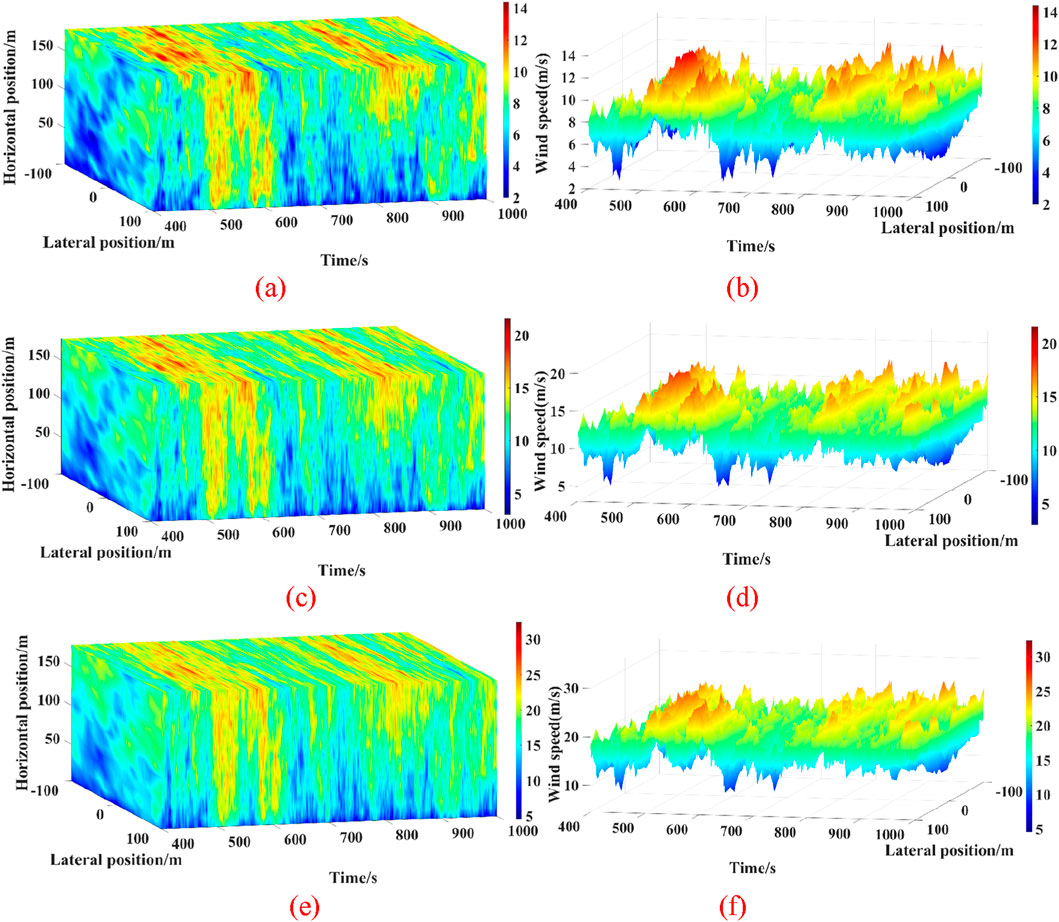
Figure 2. The visualization of turbulent wind field under various environmental conditions. (a) Wind speed distribution on rotor plane-8 m/s (b) Wind speed distribution at hub-8 m/s. (c) Wind speed distribution on rotor plane-12 m/s (d) Wind speed distribution at hub-12 m/s. (e) Wind speed distribution on rotor plane-18 m/s (f) Wind speed distribution at hub-18 m/s.
4.2 Dynamic behavior of the support structures
To comprehensively investigate the effectiveness of the tower-top feedback control of the large-scale wind turbine, key performance indicators regarding displacement and acceleration at the tower-top, as well as mudline bending moment of the supported structure of the wind turbine have been analyzed under mild, regular, and severe environmental loadings.
4.2.1 Tower-top displacement
Figure 3 shows the tower-top displacement about x and y axis of the 15 MW monopile-type wind turbine subjected to different tower-top feedback control parameters under LC5, LC9 and LC15, respectively. As can be seen, the tower-top displacement about x and y axis is respectively decreased with a KI value of 0.02. Specifically, the average values of tower-top displacement about x axis of the wind turbine are 0.62 m and 0.59 m with the KI values of 0.02 and 0.1, respectively, under a 12 m/s wind speed condition. The corresponding value of wind turbine without tower-top feedback control is achieved at 0.58 m. It means that the tower-top displacement about x axis of the wind turbine is increased by up to 7.92% and 2.13%, respectively. However, the displacement at the tower-top about y axis is reduced by 8.88% and 8.24% with KI values of 0.02 and 0.1. The findings indicate that the tower-top feedback control plays a crucial part in mitigating the tower-top displacement about y axis of the wind turbine under the 12 m/s wind speed condition.
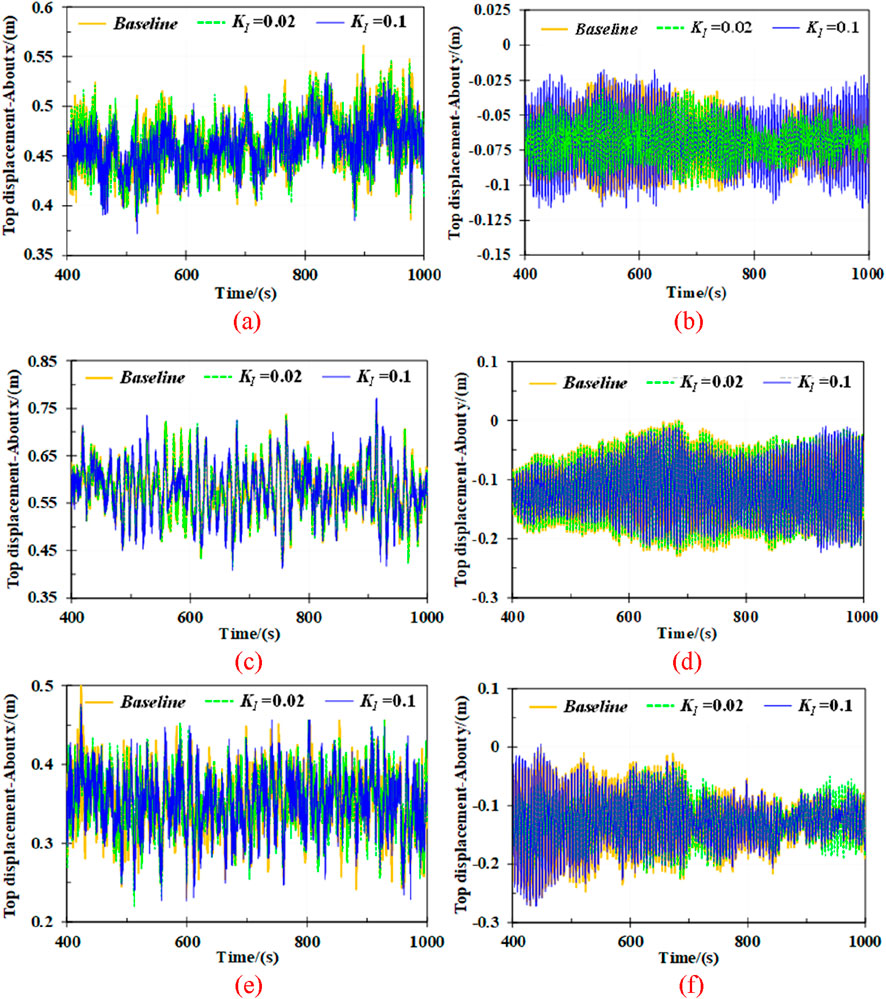
Figure 3. Tower-top displacement under examined LCs. (a) about x axis-LC5 (b) about y axis-LC5. (c) about x axis-LC9 (d) about y axis-LC9. (e) about x axis-LC15 (f) about y axis-LC15.
Moreover, as shown in the Figure 3a,b, the tower-top displacement is considerably decreased due to feedback control, particularly under a relative mild wind speed condition. Notably, the tower-top displacement about x axis of the wind turbine is mitigated by up to 0.91% and 0.65% due to feedback control compared to the baseline value of 0.46 m. Similarly, the total displacement is also reduced by 0.88% and 0.64%, respectively, under an 8 m/s wind speed condition. On top of that, when wind speed increases to 18 m/s, a reduction in tower-top displacement is observed due to feedback control. The standard deviation values of displacement at the tower-top about y axis are 0.039 m and 0.048 m, respectively, representing reductions by up to 23.62% and 5.19%, compared to the value of 0.51 m without control.
These findings demonstrate that the effect of tower-top feedback control is more considerable under a relatively lower (8 m/s) or higher (18 m/s) wind speed compared to the 12 m/s. This can be attributed to the fact that the significant aerodynamic response is generated due to feedback control at tower-top under wind speeds close to rated operational modes of the wind turbine. Particularly, the feedback control results in amplified force fluctuations, which in turn intensify the structural response at the tower-top of the wind turbine. Since the aerodynamic behavior is achieved the most severe at the rated rotor speed, the effectiveness of feedback control in mitigation of tower-top displacement is more excellent under relatively mild and severe sea conditions.
The statistic values including maximum, average and standard deviations of the tower-top displacements of the wind turbine are presented in Figure 4. It can be seen that the maximum values of displacement are mitigated with KI values of 0.02 and 0.1 under the 4 m/s to 9 m/s wind speed conditions. However, when the wind speed increases to between 11 m/s and 16 m/s, the tower-top displacement is significantly amplified with a 0.02 KI value. It means that the structural response of wind turbine is increased due to tower-top acceleration feedback control. Similar to maximum values, the average and standard deviation have also shown a significant increase under the 12 m/s wind speed scenario. This is because the aerodynamic responses of the wind turbine are the most pronounced when the rotor speed and thrust approach the rated values, which would be more intense with the implement of tower-top feedback control.
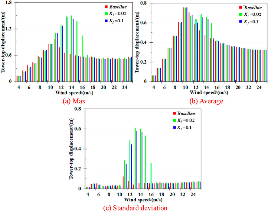
Figure 4. Statistics of tower-top displacement under all examined LCs. (a) Max (b) Average. (c) Standard deviation.
Moreover, it is evident that the displacement at the tower-top of the wind turbine is notably reduced due to the KI value of 0.1 under most of mild and severe environmental scenarios. This demonstrates that appropriately feedback control with consideration of specific environmental loadings can positively mitigate the tower-top displacement, thereby improving the safety and structural reliability of the support structural of the IEA 15 MW monopile-type wind turbine.
4.2.2 Tower-top acceleration
The variation trend of the tower-top acceleration about x and y axis of the wind turbine with different damping gain control parameters under mild, regular, and severe sea conditions have been presented in Figure 5. As seen in the figures, the acceleration at the tower-top about both x and y axis at the top of the tower are significantly mitigated due to the KI value of 0.1. However, the mitigation effect is more pronounced with a KI value of 0.02 under the mild sea state. Specifically, the standard deviation of the tower-top acceleration about y axis under an 18 m/s wind speed condition is 0.15 m/s2 without feedback control. The corresponding values of the wind turbine with KI values of 0.02 and 0.1 achieves 0.12 m/s2 and 0.14 m/s2, respectively, representing the reductions by 20.48% and 4.65%. This indicates that tower-top acceleration feedback control makes a positive effect on mitigating acceleration of the wind turbine under most sea scenarios.
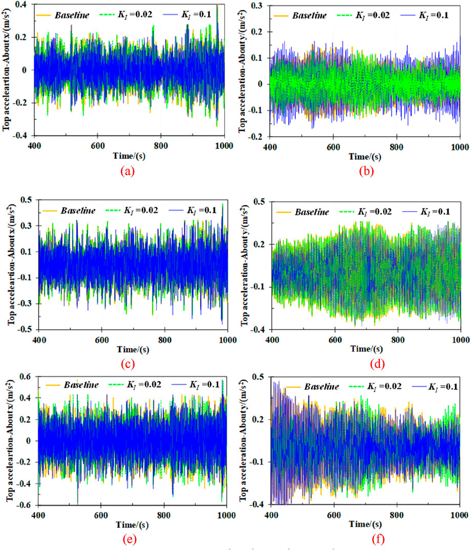
Figure 5. Tower-top acceleration under examined LCs. (a) about x axis-LC5 (b) about y axis-LC5. (c) about x axis-LC9 (d) about y axis-LC9. (e) about x axis-LC15 (f) about y axis-LC15.
However, the different trend to top displacement can be found under the nearly rated wind speed condition. The tower-top acceleration is respectively increased by up to 93.83% and 76.76% with a KI value of 0.02 compared to that of the wind turbine without feedback control. It once again proves that for the wind turbine operates under the 12 m/s wind speed condition, there is no need to implement the feedback control. It also indicates that the effectiveness of feedback control is closely correlated with environmental conditions.
Figure 6 compares the statistical values of tower-top acceleration with different feedback control parameters under all examined LCs. It can be observed in the figures that the statistics of the acceleration across reduced with a KI value of 0.1 under wind speeds ranging from 4 m/s to 11 m/s and some of severe sea conditions. However, the acceleration has been amplified under 12 m/s to 13 m/s wind speed scenarios. Specifically, the standard deviation values without feedback control is achieved at 0.20 m/s2 under nearly the rated wind speed condition (12 m/s). The corresponding values due to feedback control with KI values of 0.02 and 0.1 are 0.28 m/s2 and 0.23 m/s2. It is equivalent to increases by up to 40.29% and 17.37%, respectively.
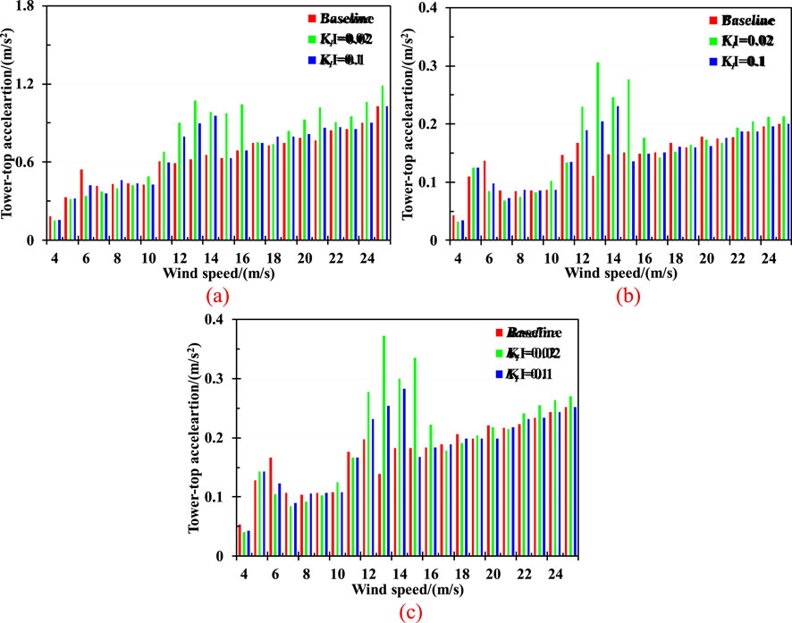
Figure 6. Statistics of tower-top acceleration under all examined LCs. (a) Max (b) Average. (c) Standard deviation.
Moreover, the tower-top acceleration is mitigated the most significantly with a KI value of 0.1 under most sea scenarios. The largest reduction in average is achieved by up to 38.50% and 28.60% under a 6 m/s wind speed condition with KI values of 0.02 and 0.1, respectively. Although the tower-top acceleration is further reduced when KI is set to 0.02, the mitigated effect is better with a KI value of 0.1 in the majority of sea conditions. For instance, it is reduced by up to 10.33% with a KI value of 0.1, however, the corresponding result is increased by up to 82.81% with a KI value of 0.02 under the 15 m/s wind speed scenario. In addition, the top tower acceleration is achieved already nearly doubles with a 0.02 KI feedback control at a wind speed of 13 m/s. Therefore, setting the feedback damping KI to 0.1 is more beneficial for reducing the top structural response of the wind turbine under most sea scenarios.
4.2.3 Mudline bending moment of the support structure
The mudline bending moment is one of the most significant output parameters for assessing the structural safety of a wind turbine. Figure 7 presents the rolling and pitching bending moment of the pile foundation for the monopile-type wind turbine with different KI values under LC5, LC9, and LC15, respectively. As observed, the feedback control makes a more dramatic effect in mudline bending moment under an 8 m/s wind speed scenario. Specifically, the average values in rolling bending moment with KI values of −1, 0.02, and 0.1 achieve at 14.2 MN·m, 13.9 MN·m, and 15.0 MN·m, respectively. It is equivalent to a 1.57% reduction and 6.18% increase with KI values of 0.02 and 0.1. Moreover, the reductions are exhibited by up to 7.49% and 1.82% under an 18 m/s wind speed.
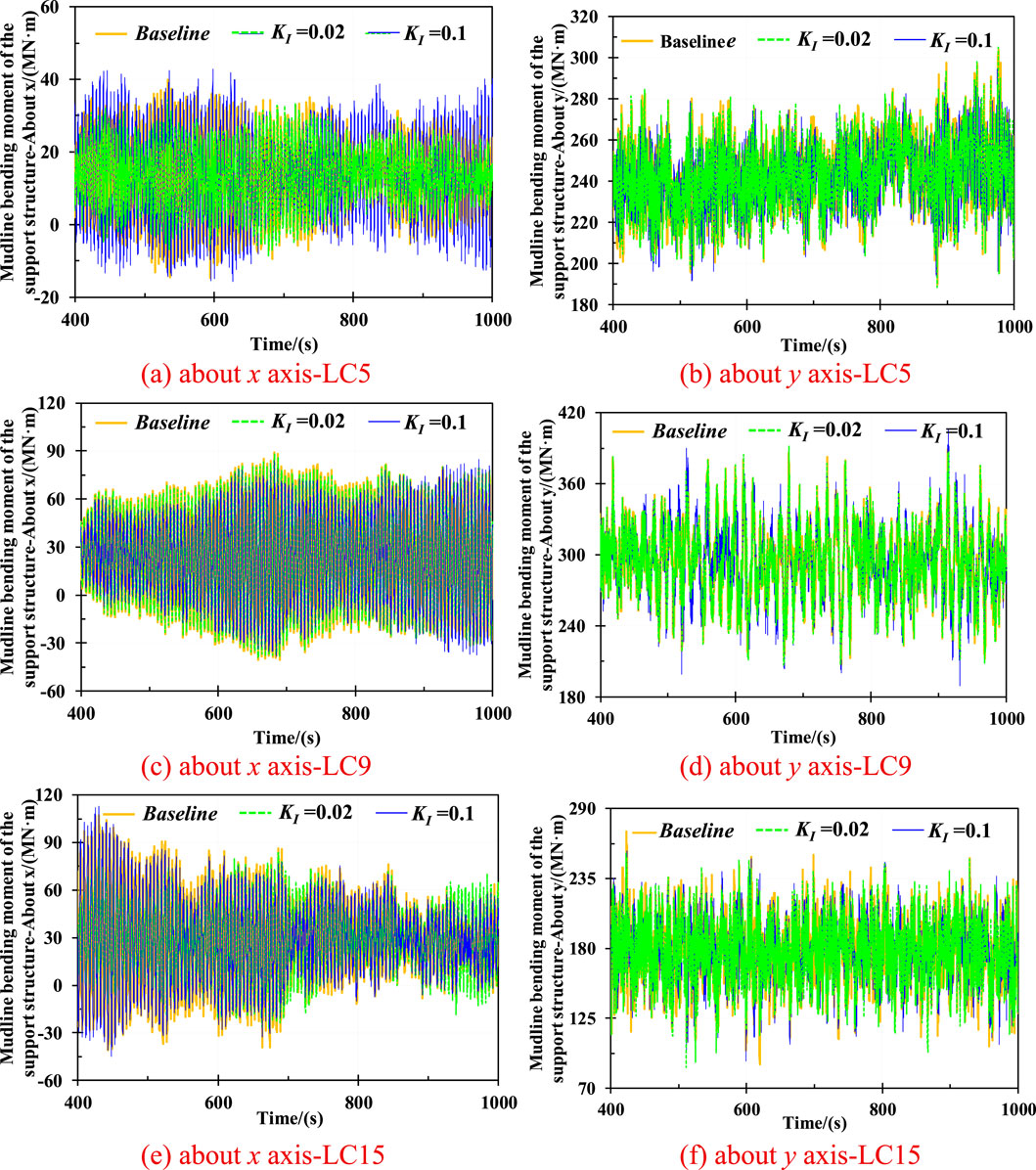
Figure 7. Mudline bending moment of the support structure under LC5, LC9, and LC15. (a)about x axis-LC5 (b) about y axis-LC5. (c) about x axis-LC9 (d) about y axis-LC9. (e) about x axis-LC15 (f) about y axis-LC15.
In addition, the pitching bending moment of the pile foundation is also experienced the reductions. Specifically, the standard deviation values with KI values of −1, 0.1, and 0.02 are achieved at 15.33 MN·m, 13.07 MN·m, and 13.81 MN·m, respectively, under an 8 m/s wind speed condition, representing the mitigations reaching 14.72% and 9.89% compared to that with baseline. Moreover, the mitigation by up to 1.98% is exhibited due to a KI value of 0.1 under a relatively higher wind speed condition, however, there exists an increase by up to 14.91% with a KI value of 0.02.
Consequently, the above data shows that the mudline bending moment in rolling and pitching can be amplified due to feedback control under the nearly rated speeds of the wind turbine, which is similar to the displacement and acceleration.
Figure 8 shows the statistical values of mudline bending moment of the support structure with various KI values under the wind speeds ranging from 4 m/s to 25 m/s. As shown in Figure 8a, the maximum values are mitigated due to a KI value of 0.1 in most sea scenarios. However, it is amplified with feedback control under the wind speeds between 11 m/s and 14 m/s. Notably, it can be observed that when wind speed reaches 15 m/s and 16 m/s, the mudline bending moment is respectively increased by up to 7 and 3 times with a KI value of 0.02 compared to the baseline. Conversely, there exists a slight increase of 1.27% with a KI value of 0.1. The above data shows that a KI of 0.1 is generally more effective in mitigating the mudline bending moment in most environmental scenarios. The most significant reduction in maximum, average and standard deviation is respectively achieved by up to 15.27%, 0.83%, and 24.46% under a 6 m/s wind speed scenario. In addition, it is noted that the feedback control has a minor influence in the average mudline bending moment, with a more notable effect on the variation and transient behavior of the structural response of the wind turbine.
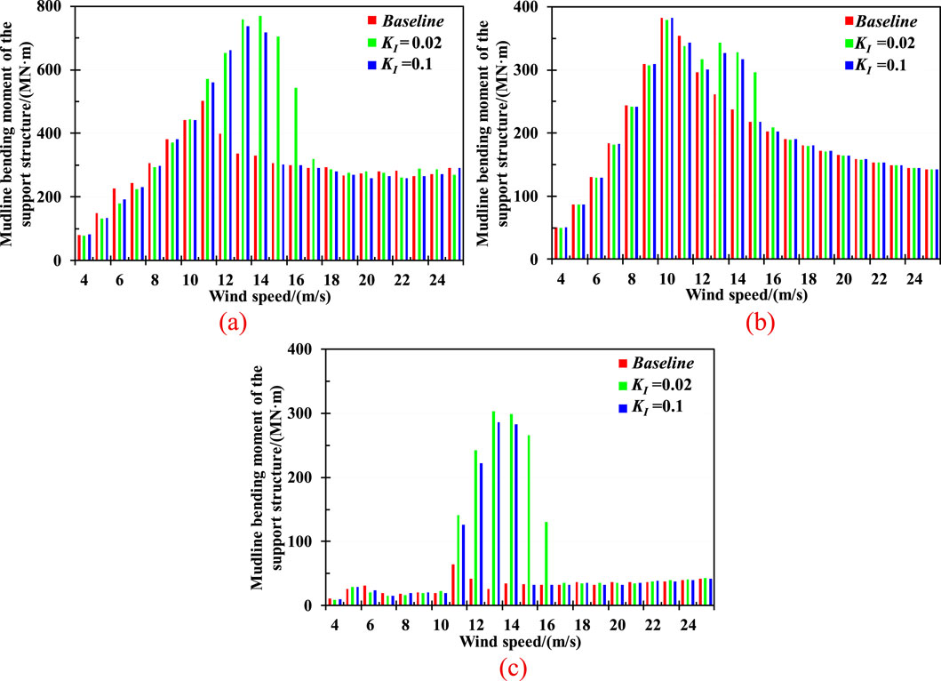
Figure 8. Statistics of mudline bending moment of the support structure under all examined LCs. (a) Max (b) Average. (c) Standard deviation.
4.3 Fatigue analysis of the support structures
Reasonable acceleration feedback control parameters can significantly reduce the structural response of the tower and pile foundation, thereby decreasing the fatigue load of the wind turbine. However, it may also lead to more intense responses if the control strategy is inappropriate or excessively adjusted. Therefore, to systematically explore the impact of tower-top acceleration feedback control on the fatigue load of predominant structural components of the wind turbine, the axial stress and accumulated fatigue damage at the pile and tower have been comprehensively studied.
4.3.1 Axial stress analysis
4.3.1.1 Tower-base
Figure 9 presents the axial stress at tower-base of wind turbine under mild, regular, and severe conditions. As can be seen in the Figure 9a, the fluctuation of axial stress with a KI of 0.02 is significantly reduced compared to that without feedback control. Specifically, the standard deviation values with KI values of −1, 0.02, and 0.1 are achieved at 2.26 MPa, 1.65 MPa, and 2.78 MPa under an 8 m/s wind speed scenario, respectively. It is equivalent to the reduction of 26.99% with a KI value of 0.02, while there exists an increase of 23.01% with a 0.1 KI. However, the average values of axial stress at tower-base are 16.968 MPa, 16.967 MPa, and 16.962 MPa, indicating that feedback control makes little negative influence in the average level of the axial stress of wind turbine.
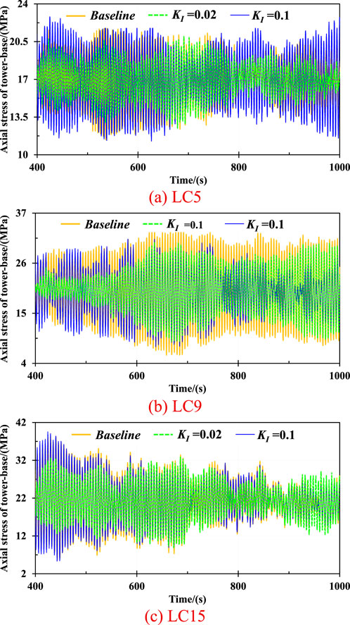
Figure 9. The axial stress of wind turbine at tower-base under various environmental loadings. (a) LC5. (b) LC9. (c) LC15.
The above data shows that the appropriate feedback control design can effectively mitigate the fluctuation in fatigue damage at the tower-base under wind speeds of 8 m/s and 18 m/s, thereby improving the structural safety of the wind turbine.
4.3.1.2 Sea water level
Figure 10 presents the axial stress at the SWL of the wind turbine under the mild, regular, and severe environmental conditions, respectively. As can be seen, the acceleration feedback control makes a difference in mitigating the axial stress under complicated sea scenarios, especially in the 8 m/s wind speed scenario. Specifically, the variation of axial stress at the SWL of wind turbine with a KI value of 0.02 is remarkably reduced compared to the baseline. The standard deviation values with KI values of −1, 0.02, and 0.1 are 2.29 MPa, 1.68 MPa, and 2.82 MPa, respectively. It means that the fluctuation in axial stress at the SWL subjected to a KI value of 0.02 is significantly decreased by up to 26.64%, while it is increased reaching 23.14% with a KI value of 0.1 under an 8 m/s wind speed condition.
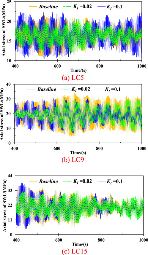
Figure 10. The axial stress of wind turbine at SWL under various environmental loadings. (a) LC5. (b) LC9. (c) LC15.
Moreover, the average values of axial stress at the SWL of the wind turbine are 19.23 MPa, 19.21 MPa, and 18.66 MPa under the 12 m/s wind speed condition, respectively. It represents that the reductions in fatigue stress are achieved by 2.96% with a KI value of 0.1. When the wind speed turns to 18 m/s, the mitigated fluctuations are exhibited with KI values of 0.02 and 0.1, reaching 22.97% and 5.31%.
The above data indicates that the appropriate feedback control parameter can effectively decrease the axial stress at SWL, thereby enhancing the structural safety and improving the lifespan of the wind turbine.
4.3.1.3 Mudline of the support structure
Figure 11 illustrates the axial stress of the wind turbine at the mudline of the support structure under various environmental loadings. As observed, the acceleration feedback control can significantly mitigate the fluctuation of axial stress under the mild, regular, and severe sea scenarios, especially with the KI value of 0.02. Specifically, the standard deviation values of axial stress with KI values of 0.02 and 0.1 are 7.35 MPa, 4.92 MPa, and 5.22 MPa, respectively, under a 12 m/s wind speed condition. It means that the feedback control with KI values of 0.02 and 0.1 can reduce the axial stress at the mudline of the wind turbine by up to 33.06% and 28.98%, respectively. Moreover, the axial fatigue stress at the pile foundation is respectively reduced by 22.19% and 5.24% due to the tower-top acceleration feedback control subjected to the severe sea loadings, which indicates that the appropriate feedback control can effectively improve the structural safety at the pile foundation of the wind turbine.
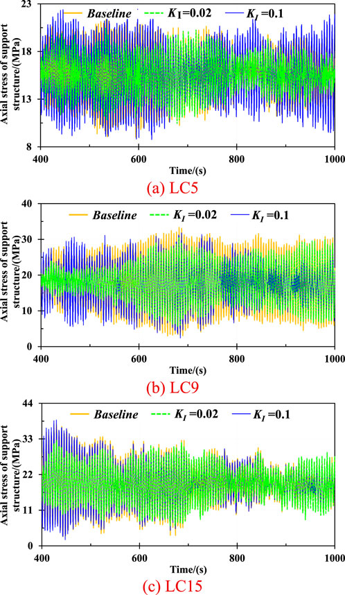
Figure 11. Axial stress of wind turbine at mudline under various environmental loadings. (a) LC5. (b) LC9. (c) LC15.
4.3.2 Accumulated fatigue damage analysis
4.3.2.1 Accumulated fatigue damage
Figure 12 shows the accumulated axis fatigue damage of the wind turbine at SWL with respect to various feedback control under an angle of 90 deg in 8 m/s, 12 m/s, and 18 m/s wind speed scenario. As observed, the variation in the accumulated fatigue damage of wind turbine components due to feedback control is consistent under the mild and severe conditions.
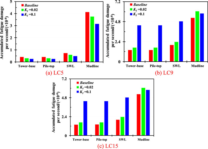
Figure 12. Accumulated fatigue load of wind turbine under various environmental loadings. (a) LC5. (b) LC9. (c) LC15.
Moreover, the axial fatigue damage is significantly reduced with a KI value of 0.02 under the wind speed of 8 m/s and 18 m/s. Specifically, the axial fatigue load with a KI value of 0.02 is 7.88 × 10⁻¹¹, which exhibiting a 13.46% reduction compared to 9.11 × 10⁻¹¹ without tower-top acceleration feedback control under an 8 m/s wind speed scenario. The overall variation in accumulated fatigue damage is incredibly decreased due to the appropriate feedback control, with the largest reduction of 52.94% at 90 deg. In addition, the variation trend of the fatigue damage at the tower-base of the wind turbine is similar to that at the SWL. The impact of different tower-top acceleration feedback control coefficients on the wind turbine fatigue damage is significantly comparable. The largest mitigation is respectively exhibited by up to 16.39% and 46.22% with KI values of 0.02 and 0.1 compared to that without feedback control. A similar trend is found in the fatigue damage at the pile foundation with a KI value of 0.1.
However, a notable difference emerges under the 12 m/s wind speed scenario. Specifically, the accumulated fatigue damage at the tower-base, pile-top, and SWL of the wind turbine is increased as the KI values rise, while the most significant fatigue load is achieved with a KI value of 0.02. The observations indicate that there is no need to implement a tower-top acceleration feedback control under the 12 m/s wind speed condition. This is because the wind turbine operates with optimal aerodynamic performance near the rated wind speed, resulting in an increase of dynamic responses at the tower and support structure.
To recapitulate, the above findings indicate that the reasonable feedback control parameters can effectively reduce the axial fatigue damage of wind turbine under the mild and severe conditions, thereby enhancing the structural safety, reliability, and lifespan.
4.3.2.2 Fatigue damage under all examined LCs
Figure 13 presents the fatigue damage of the wind turbine at different key components with respect to various KI values under all examined LCs. As can be observed, the effectiveness of tower-top acceleration feedback control is highly influenced by environmental loadings. Notably, when the wind turbine operates near its rated rotor speed, feedback control is unnecessary. The fatigue damage of the wind turbine is significantly increased at wind speeds between 11 m/s and 14 m/s. Specifically, the fatigue damage at tower-base with KI values of 0.02 and 0.1 is respectively increased by up to 29.00% and 99.97% at a wind speed of 13 m/s. The fatigue damage at the SWL also experiences a significant increase, reaching 24.84% and 99.95%. The considerable increase in fatigue damage at the support structure presents a serious threat to the structural integrity and operational safety of the wind turbine.
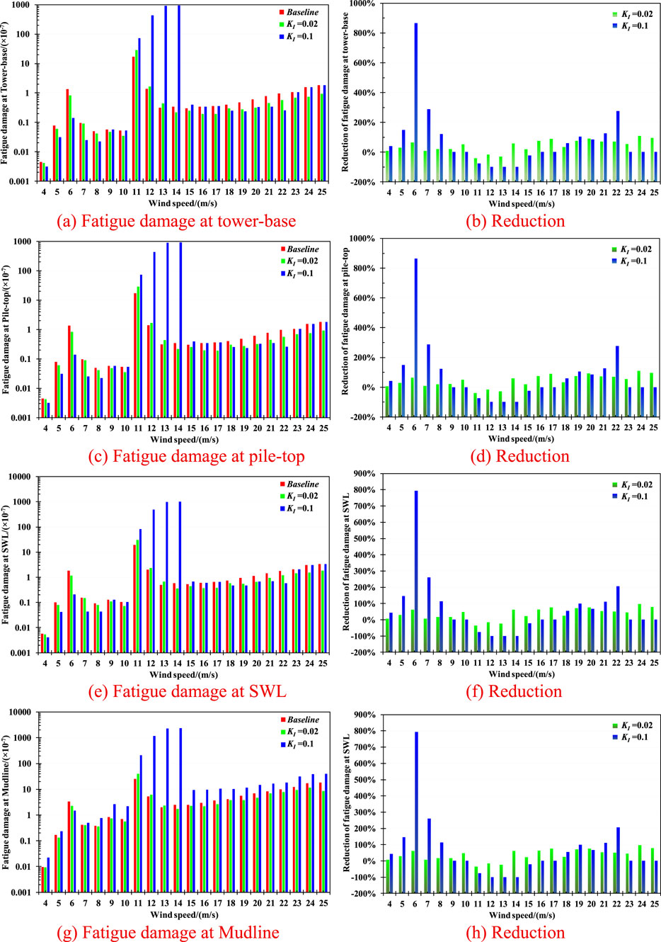
Figure 13. The fatigue damage and corresponding reductions of wind turbine at various positions under all the examined LCs. (a) Fatigue damage at tower-base (b) Reduction. (c) Fatigue damage at pile-top (d) Reduction. (e) Fatigue damage at SWL (f) Reduction. (g) Fatigue damage at Mudline (h) Reduction.
However, it is found that when the wind speed exceeds 15 m/s, the acceleration feedback control makes a positive influence in mitigating the fatigue damage of the wind turbine, particularly with a KI value of 0.02. Specifically, the fatigue damage at the tower-base is significantly decreased at wind speeds between 15 m/s and 25 m/s. The largest reduction is achieved by up to 90.76% with a KI value of 0.02 under a 20 m/s wind speed scenario, while a 84.24% reduction is observed with a KI value of 0.1. Similarly, the fatigue damage at the SWL is also notably mitigated under these severe conditions. Different from the results of tower-base, the effect of tower-top acceleration feedback control performs better with a KI value of 0.1, achieving a maximum reduction of 126.15% under a 21 m/s wind speed scenario.
Conversely, discrepancies are observed in the fatigue damage of various components of the wind turbine. Specifically, the fatigue damage at the mudline all experiences an increase with a KI value of 0.1, while exhibiting a significant decrease with a KI value of 0.02 at the wind speeds above 15 m/s. It suggests that the acceleration feedback control with a KI value of 0.1 makes a negative effect on the fatigue damage at the mudline, whereas the KI value of 0.02 performs more effectively. The above findings indicate that the tower-top feedback control is highly effective in mitigating the fatigue damage of the monopile-type wind turbine under the severe conditions. A similar trend can be found under milder environmental scenarios, where the fatigue damage at the tower-base, pile-top, and SWL is dramatically reduced due to tower-top feedback control, especially with a KI value of 0.1.
5 Conclusion
To better ensure the operational safety of large-scale OWTs, tower-top acceleration feedback control has become particularly significant. It can effectively mitigate tower-top displacement and acceleration, meanwhile enhancing the stability of the pile foundation of wind turbines. An IEA 15 MW wind turbine has been adopted in this study to systemically investigate the effect of tower-top acceleration feedback control on the structural response of the wind turbine under complex environmental loadings. Key performance indicators regarding the tower-top displacement, acceleration, and pile foundation bending moments are compared to those obtained without control. The fatigue damage of the key components of the wind turbine has also been evaluated. The obtained findings demonstrate that appropriate acceleration feedback control design can significantly alleviate fatigue damage and enhance aerodynamic stability of wind turbines. Specific research findings are summarized as follows:
1. The tower-top feedback control makes a positive effect on enhancing the dynamic performance of the monopile-type wind turbine under complex environmental loadings. Specifically, the tower-top displacement, acceleration, and pile foundations bending moments are effectively mitigated under both mild and severe scenarios, with the exception of conditions close to rated wind speeds. It is because that the rotor speed reaches the rated with an optimal aerodynamic performance when the wind turbine operates approach the rated wind speed. At this time, the tower-top acceleration feedback control is likely to cause resonance and phase lag of aerodynamic damping, leading to sudden increase in rotor thrust and tower-base loads.
2. Feedback control effectiveness in mitigating fatigue damage of wind turbine is closely associated with the environmental loadings. The fluctuations in tower-top displacement, acceleration, and mudline bending moment are amplified approach the rated wind speed conditions. The impact of tower-top acceleration feedback control is particularly pronounced especially in the 6 m/s to 11 m/s and 15 m/s to 25 m/s wind speed ranges. Therefore, it is of great significance to implement a feedback control of wind turbine under mild and severe environmental loadings.
3. The tower-top displacement, acceleration, and mudline bending moment of the support structures are significantly reduced due to feedback control. Specifically, the maximum value of tower-top displacement is mitigated with KI values of 0.02 and 0.1 at wind speeds ranging from 4 m/s to 9 m/s. In addition, the largest mitigation in the lateral acceleration is achieved by up to 38.50% and 28.60% under a 6 m/s wind speed scenario, respectively. This indicates that an appropriate KI value can alleviate the aerodynamic response and enhance the structural safety of the monopile-type wind turbine.
4. The accumulated fatigue damage of the wind turbine has been significantly mitigated due to the feedback control of tower-top under mild and severe conditions. The fatigue damage at the tower-base, pile-top, and SWL are decreased with KI of 0.02 and 0.1 under the wind speeds ranging from 16 m/s to 22 m/s. Meanwhile, the KI value of 0.02 performs better at the mudline of the support structure. It once again proves that the appropriate design of tower-top feedback control can effectively reduce the structural loads, thereby enhancing the lifespan, and operational safety of wind turbine under complex environmental loadings.
The limitations of this study are presented as follows:
1. Due to the technical complexity and prohibitive costs experimental test, this study only investigated the tower-top feedback control effectiveness based on the open-source software OpenFAST. However, it is of great significance to conduct physical modelling tests to comprehensively ensure the completeness and reliability of the results. Subsequent experimental tests will be carried out to certificate the findings in this study.
2. Although the KI value of the tower-top feedback control has been systematically analyzed in this study, the impact of KP value that is another significant component of PI controller of the wind turbine has not been thoroughly investigated. Therefore, future research will focus on the KI and KP values at the same time to better investigate the tower-top feedback control effectiveness of the wind turbine.
3. The combined wind-wave loading analysis focused exclusively on regular environmental loadings, omitting extreme sea states that could induce nonlinear structural responses. Future study will conduct a comprehensive analysis under extreme sea scenarios including typhoon-condition, with consideration of nonlinear effects.
Data availability statement
The original contributions presented in the study are included in the article/supplementary material, further inquiries can be directed to the corresponding author.
Author contributions
YL: Writing – review and editing, Writing – original draft, Data curation, Conceptualization, Formal Analysis. BH: Writing – original draft, Software, Investigation, Conceptualization, Writing – review and editing. JD: Writing – original draft, Methodology. NL: Data curation, Writing – original draft. YY: Investigation, Writing – review and editing, Data curation, Project administration, Writing – original draft.
Funding
The author(s) declare that financial support was received for the research and/or publication of this article. The authors are grateful for the financial support from the National Natural Science Foundation of China (Grant No.: 52301343, 52476205, 52271294), Natural Science Foundation of Zhejiang Province (Grant No.: LQ23E090003), “Leading Goose” R&D Program of Zhejiang (No. 2023C03122).
Conflict of interest
Authors YL, BH, and NL were employed by PowerChina Huadong Engineering Corporation Limited.
The remaining authors declare that the research was conducted in the absence of any commercial or financial relationships that could be construed as a potential conflict of interest.
Generative AI statement
The author(s) declare that no Generative AI was used in the creation of this manuscript.
Any alternative text (alt text) provided alongside figures in this article has been generated by Frontiers with the support of artificial intelligence and reasonable efforts have been made to ensure accuracy, including review by the authors wherever possible. If you identify any issues, please contact us.
Publisher’s note
All claims expressed in this article are solely those of the authors and do not necessarily represent those of their affiliated organizations, or those of the publisher, the editors and the reviewers. Any product that may be evaluated in this article, or claim that may be made by its manufacturer, is not guaranteed or endorsed by the publisher.
References
Brodersen, M. L., Bjørke, A. S., and Høgsberg, J. (2017). Active TMD for damping of OWT vibrations. Wind Energy 20 (5), 783–796. doi:10.1002/we.2063
Cetrini, A., Cianetti, F., Corradini, M. L., Ippoliti, G., and Orlando, G. (2019). On-line fatigue alleviation for wind turbines by a robust control approach. Int. J. Electr. Power and Energy Syst. 109, 384–394. doi:10.1016/j.ijepes.2019.02.011
Chen, Z., Wang, L., Wang, L., Hong, Y., Zhang, B., and Yang, Q. (2024). Integrated analysis of hybrid control for offshore wind turbines: a case study in wave resonance prone wind farms. Ocean. Eng. 298, 117176. doi:10.1016/j.oceaneng.2024.117176
Grant, E., Johnson, K., Damiani, R., Stockhouse, D., Dinius, J., Phadnis, M., et al. (2022). “Combined low-bandwidth platform actuation and floating feedback control for an OWT with an ultraflexible substructure,” in 2022 American Control Conference (ACC) (IEEE), 3526–3531.
Hwas, A., and Katebi, R. (2012). Wind turbine control using PI pitch angle controller. IFAC Proc. Vol. 45 (3), 241–246. doi:10.3182/20120328-3-it-3014.00041
Jassmann, U., Zierath, J., Dickler, S., and Abel, D. (2016). “Model predictive wind turbine control for load alleviation and power leveling in extreme operation conditions,” in 2016 IEEE Conference on Control Applications (CCA) (IEEE), 1368–1373.
Jonkman, J. (2008). “Influence of control on the pitch damping of a floating wind turbine,” in 46th AIAA aerospace sciences meeting and exhibit, 1306.
Kumar, A. A., Hugues-Salas, O., Savini, B., and Keogh, W. (2016). Tower based load measurements for individual pitch control and tower damping of wind turbines. J. Phys, Conf. Ser. 753 5 052024. doi:10.1088/1742-6596/753/5/052024
Lenfest, E., Goupee, A. J., Wright, A., and Abbas, N. (2020). “Tuning of nacelle feedback gains for floating wind turbine controllers using a two-DOF model,” in International Conference on Offshore Mechanics and Arctic Engineering (American Society of Mechanical Engineers). doi:10.1115/omae2020-18770
Lio, W. H., Jones, B. L., and Rossiter, J. A. (2018). Estimation and control of wind turbine tower vibrations based on individual blade-pitch strategies. IEEE Trans. Control Syst. Technol. 27 (4), 1820–1828. doi:10.1109/tcst.2018.2833064
Long, T., Yang, Q., Wang, Q., Huang, G., Zhou, X., and Yang, Y. (2023). Active vibration control of wind turbine using virtual TMD algorithm based on aerodynamic-structure-servo coupling model. Struct. Control Health Monit. 2023 (1), 1–26. doi:10.1155/2023/6618783
Mohammadi, E., Fadaeinedjad, R., and Moallem, M. (2014). A new control strategy to suppress the tower vibrations of variable speed wind turbines. J. Renew. Sustain. Energy 6 (3), 033106. doi:10.1063/1.4871470
Nam, Y., Kien, P. T., and La, Y. H. (2013). Alleviating the tower mechanical load of multi-MW wind turbines with LQR control. J. Power Electron. 13 (6), 1024–1031. doi:10.6113/jpe.2013.13.6.1024
Pamososuryo, A. K., Mulders, S. P., Ferrari, R., and van Wingerden, J. W. (2024). On the analysis and synthesis of wind turbine side–side tower load control via demodulation. IEEE Trans. Control Syst. Technol. 32, 1865–1880. doi:10.1109/tcst.2024.3377508
Pascu, V., Kanev, S., and van Wingerden, J. W. (2017). Adaptive tower damping control for offshore wind turbines: adaptive tower damping control for offshore wind turbines. Wind Energy 20 (5), 765–781. doi:10.1002/we.2058
Perrone, F. (2015). “OWT tower fore-aft control: trade-off fatigue load reduction and pitch activity,” in 2015 European Control Conference (ECC) (IEEE), 2444–2448.
Ren, L., Yang, H., Liu, S., and Liu, F. (2015). “Passivity-based control of tower vibration of OWTs,” in 2015 34th Chinese Control Conference (CCC) (IEEE), 934–939.
Schlipf, D., Grau, P., Raach, S., Duraiski, R., Trierweiler, J., and Cheng, P. W. (2014). “Comparison of linear and nonlinear model predictive control of wind turbines using LIDAR,” in 2014 American Control Conference (IEEE), 3742–3747.
Wang, L., Bergua, R., Robertson, A., Wright, A., Zalkind, D., Fowler, M., et al. (2024). Experimental investigation of advanced turbine control strategies and load-mitigation measures with a model-scale floating offshore wind turbine system. Appl. Energy 355, 122343. doi:10.1016/j.apenergy.2023.122343
Wu, X., and Wang, W. C. (2022). “Active structure control of floating wind turbine using PID controller,” in 2022 IEEE/IAS industrial and commercial power system asia (I&CPS asia) (IEEE), 783–789.
Yang, Z., and Li, Y. (2018). Active vertical vane control for stabilizing platform roll motion of floating offshore turbines. Wind Energy 21 (11), 997–1010. doi:10.1002/we.2209
Yang, Y., Bashir, M., Michailides, C., Li, C., and Wang, J. (2020). Development and application of an aero-hydro-servo-elastic coupling framework for analysis of floating offshore wind turbines. Renew. Energy 161, 606–625. doi:10.1016/j.renene.2020.07.134
Keywords: offshore wind energy, monopile-type wind turbine, tower-top feedback control, structural response, fatigue damage
Citation: Lai Y, He B, Ding J, Lyu N and Yang Y (2025) Effects of tower-top acceleration feedback control on the dynamic response of support structures of a 15 MW monopile-type wind turbine. Front. Energy Res. 13:1646687. doi: 10.3389/fenrg.2025.1646687
Received: 13 June 2025; Accepted: 11 August 2025;
Published: 28 August 2025.
Edited by:
Matilde Santos, Complutense University of Madrid, SpainReviewed by:
Bofeng Xu, Hohai University, ChinaHaiying Sun, South China University of Technology, China
Copyright © 2025 Lai, He, Ding, Lyu and Yang. This is an open-access article distributed under the terms of the Creative Commons Attribution License (CC BY). The use, distribution or reproduction in other forums is permitted, provided the original author(s) and the copyright owner(s) are credited and that the original publication in this journal is cited, in accordance with accepted academic practice. No use, distribution or reproduction is permitted which does not comply with these terms.
*Correspondence: Yang Yang, eWFuZ3lhbmcxQG5idS5lZHUuY24=