 Duc-Dung Le1†
 Huu-Linh Nguyen
 Sangseok Yu
 Hoang Hiep Le
 Tuan-Dung Hoang
- 1School of Mechanical Engineering, Hanoi University of Science and Technology, Hanoi, Vietnam
- 2Department of Mechanical Engineering, Graduate School, Chungnam National University, Daejeon, Republic of Korea
- 3School of Mechanical Engineering, Chungnam National University, Daejeon, Republic of Korea
- 4School of Chemistry and Life Sciences, Hanoi University of Science and Technology, Hanoi, Vietnam
- 5Vietnam National University Hanoi, School of Interdisciplinary Sciences and Arts, Hanoi, Vietnam
Solid oxide fuel cells (SOFCs) are among the most promising electrochemical technologies for high-efficiency, low-emission power generation. This review provides a comprehensive overview of recent advances in SOFC materials, system architectures, and commercialization pathways, with emphasis on intermediate-temperature operation to enhance durability and reduce costs. Developments in electrolyte materials are analyzed alongside progress in anode and cathode advances in materials. At the system level, the manuscript compares electrolyte-supported and anode-supported configurations, examines sealing technologies and thermal cycling durability in planar stacks, and discusses fuel preparation strategies with emphasis on sulfur removal from hydrocarbon fuels. The integration of direct internal reforming (DIR) SOFC systems and the role of anode gas recycle in improving efficiency and thermal management are also addressed. The high-temperature exhaust from SOFCs supports cogeneration and trigeneration applications, enabling additional power or heating/cooling through thermodynamic cycles such as Rankine and Brayton, thereby enhancing overall system efficiency. Finally, the review examines the status of commercial SOFC deployment, presenting case studies of leading industrial players such as Bloom Energy (USA), Ceres Power (UK), and SolydEra (Italy). The paper concludes with an assessment of the key challenges and perspectives for SOFC commercialization in stationary power generation, including cost reduction, stack lifetime extension, large-scale manufacturing, and system integration strategies required to achieve widespread market adoption.
1 Introduction
Renewable and environmentally friendly energy solutions have been expanding globally in response to rising global energy demand and pollution from the use of fossil fuels (Damo et al., 2019; Nguyen et al., 2023). Alternatives to fossil fuel-based power production may be found in renewable energy sources including solar, wind, hydro, and geothermal, which do not directly emit greenhouse gases during operation (Buonomano et al., 2015). It is commonly agreed that a renewable energy-powered hydrogen economy, complete with hydrogen generation, storage, and electricity generation, is the way to go. When hydrogen is created using renewable energy sources, the hydrogen economy has the potential to almost eliminate emissions of greenhouse gases (Jiao et al., 2021). Solid oxide technology is also increasingly applied in solid oxide electrolysis cells (SOECs) for high-efficiency hydrogen generation. Operating in reverse mode, SOECs convert steam or co-feed steam and CO2 into hydrogen and syngas. Co-electrolysis, in particular, enables simultaneous H2 and CO production for downstream fuel synthesis, making it a critical technology in the renewable hydrogen economy (De Lorenzo et al., 2022). Fuel cells, the primary electrochemical devices that convert hydrogen into electricity at high efficiency, have become inextricably linked to hydrogen (Corigliano et al., 2022).
The operating principles of fuel cells, which involve the electrochemical conversion of fuel without combustion directly into electricity, have positioned them as a highly efficient and environmentally friendly option for power generation. They also offer modularity, allowing for the assembly of power plants of varying sizes, from micro-scale (<1 kW) to large-scale systems (>10 MW) (Buonomano et al., 2015). Furthermore, depending on the fuel cell’s working temperature, the heat released during the electrochemical process may be utilized for cogeneration applications like space heating or steam production. Since their working temperatures may reach up to 1,000 °C, solid oxide fuel cells (SOFCs) are especially appealing for hybridization with other power generating technologies. Theoretical efficiencies of over 70% may be achieved by combining different topologies, such as steam or organic Rankine cycles and Brayton cycles (Choudhury et al., 2013). Even when most of the thermal energy is extracted for primary heat recovery, the remaining low-grade heat can be effectively utilized in organic Rankine cycle (ORC) systems (Corigliano et al., 2024). Due to their high efficiency, SOFCs are a viable choice for environmentally friendly power production since they consume less fuel and produce less greenhouse gases.
The flexibility of SOFCs in accepting a broad variety of fuels, from hydrogen and natural gas to biogas and even carbon-based fuels like coal and biomass, is a major benefit of this technology. Because of this fuel flexibility, SOFCs may be used for a wide variety of stationary power generating applications, from individual houses to utility-scale power plants (Corigliano et al., 2022). It is a huge benefit to be able to utilize different fuels in a society that is working toward energy diversification and security. Moreover, the absence of moving parts in SOFCs further adds to their durability, endurance, and low maintenance needs, making them a desirable option for long-term operation.
With the growing demand for clean and efficient energy systems, SOFCs have garnered significant attention from researchers, industry experts, and policymakers. Research and development into SOFCs has been intensive over the last several decades to improve their efficiency, longevity, and cost-effectiveness. The outcome has been extraordinary progress that has expanded the capabilities of this technology and brought it one step closer to commercial feasibility. Despite the advances achieved, major technical and economic obstacles remain in the way of the broad deployment of SOFCs for stationary power production. Therefore, the purpose of this study is to lay out the current research trends, new technologies, and possible approaches to these issues.
This review was developed using a systematic survey of recent scientific literature, industrial reports, and demonstration projects related to SOFC technology published over the past two decades. The selection focused on materials development, system-level integration, durability, fuel processing, and commercialization pathways for stationary SOFC applications.
The manuscript follows a structured flow-path: it begins with advances in SOFC electrolytes, anodes, and cathodes as well as system-level enhancements (Section 2), then examines fuel preparation and processing strategies (Section 3), before moving to current SOFC applications for stationary power generation with industrial case studies (Section 4). Finally, it discusses the challenges and perspectives for large-scale commercialization (Section 5).
2 SOFC operation, materials and designs
2.1 Operating principle of SOFC
The SOFC is one of the most effective fuel cells available (Singh et al., 2021). It consists of a cathode, an anode, and a solid oxide electrolyte. The anode side is supplied with fuel while the cathode side is supplied with an oxidant. The anode terminal breaks down the fuel into positive and negative ions, and the electrolyte allows only protons to move from the anode to the cathode. The external circuits enable free electrons to flow to the cathode terminal, where the oxygen reduction occurs. Consequently, the flow of electrons through the external circuit generates electricity. Figure 1 illustrates the operating principle of SOFC.
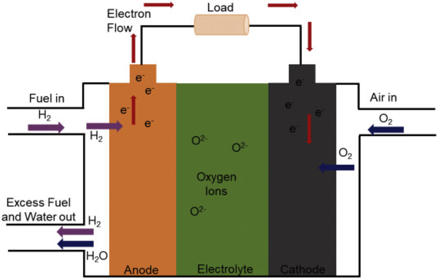
Figure 1. Basic structure and working principle of a SOFC (Singh et al., 2021).
2.2 Component and material
2.2.1 Electrolyte materials
The electrolyte is an important component of SOFC that plays a crucial role in conducting oxygen ions from the cathode to the anode while blocking electrons. It is a ceramic layer that should have several properties such as high oxide ion conductivity and low electronic conductivity. It should also be thermally and chemically stable towards the reactant environment and the electrode materials. To avoid any issues, it is essential that the thermal expansion coefficient (TEC) between electrodes and contacting components are closely matched (Mendonça et al., 2021). Among the various electrolyte materials, Yttria-stabilized zirconia (YSZ) is the most used in SOFCs. YSZ exhibits excellent ionic conductivity at high temperatures (800 °C–1,000 °C) and retains its mechanical and chemical stability (Mahato et al., 2015). Scandia-stabilized zirconia (ScSZ) is another promising material that has demonstrated superior conductivity and stability. However, the accessibility and affordability of scandia remain major concerns (Hussain and Yangping, 2020).
Recent efforts in SOFC research have focused on reducing the operating temperature to the intermediate range of 600 °C–800 °C, giving rise to Intermediate-Temperature Solid Oxide Fuel Cells (IT-SOFCs). This transition aims to address challenges related to thermal stress, material degradation, and cost associated with high-temperature SOFCs (800 °C–1,000 °C). However, reducing the operating temperature compromises ionic conductivity, necessitating the development of advanced electrolyte and electrode materials. At these lower temperatures, doped ceria has emerged as a more prevalent material for their higher ionic conductivity at intermediate temperatures compared to traditional YSZ (Sreedhar et al., 2019). Cerium gadolinium oxide (CGO) or gadolinia-doped cerium (GDC) is another solid electrolyte material that has shown better low-temperature conductivity than YSZ and ScSZ. However, it faces significant challenges in terms of mechanical stability, mixed ionic and electronic conduction behavior at low oxygen partial pressure, cost, and the availability of Gadolinium (Hussain and Yangping, 2020). To address this challenge, a variety of alternative electrolytes and a ceria-salt composite approach have been proposed (Xia et al., 2017).
Some materials that possess the ABO3-type perovskite structure have demonstrated remarkable chemical stability in both oxidizing and reducing conditions. Lanthanum gallate-based electrolytes, particularly La1-xSrxGa1-γMgγO3 (LSGM), have emerged as promising alternatives to YSZ and doped ceria for intermediate-temperature SOFCs. LSGM exhibits significantly higher oxide ion conductivity at 600 °C–800 °C compared to YSZ, due to its perovskite structure and large oxygen vacancy concentration (Mendonça et al., 2021; Hussain and Yangping, 2020; Lyu et al., 2020). LSGM electrolytes also offer good thermal expansion compatibility with commonly used electrode materials. However, concerns associated with the use of this material are mechanical stability, and compatibility with electrode materials such as nickel oxide (NiO) (Hussain and Yangping, 2020).
Oxide ion conducting materials, particularly oxide phases generated from Bi2O3, are of great interest due to their strong ionic conductivity in comparison to other solid electrolytes (Jaiswal et al., 2019). The high anion mobility and oxygen vacancy concentration (about 25 percent) contribute to its superior ionic conductivity (Corigliano et al., 2022). Bi2O3 has two stable polymorphs: the monoclinic α-phase and the cubic δ-phase. The δ-phase exhibits a high conductivity and is perhaps the best oxide ion conductor (Mahato et al., 2015; Zhang et al., 2017). However, doping with cations such as Y3+, La3+, Er3+, etc., is required to stabilize the high-temperature δ-Bi2O3 to room temperature (Mahato et al., 2015) since the δ-phase becomes unstable below 730 °C (Jaiswal et al., 2019). When cooled below 730 °C, it undergoes a phase transformation into the monoclinic α-phase, causing a sudden decrease in conductivity (Zhang et al., 2017). Due to these characteristics, Bi2O3 is not a suitable electrolyte for solid oxide fuel cells.
2.2.2 Anode materials
To function properly, an anode must meet several criteria, including high electronic conductivity, good stability factor, thermal compatibility with other cell components, efficient electrocatalytic efficiency to cause oxidation reactions, optimized porosity for efficient carrier gas transport, and a reducing atmosphere inside the cell at high temperatures (Dwivedi, 2020). Carbon-based materials and metals such as platinum, iron, cobalt, nickel, and graphite are included in this category. Nickel (Ni) has been extensively used as an anode material due to its low cost, excellent chemical stability, and outstanding catalytic activity towards hydrogen oxidation and hydrocarbon fuel reforming (Mahato et al., 2015). However, it has certain limitations, such as a different thermal expansion coefficient from the YSZ electrolyte. This leads to flaking and a predisposition to coke formation. The flaking can be decreased by incorporating YSZ into porous Ni to create a cermet and obtain an expansion coefficient comparable to that of the electrolyte, especially near the interface (Dwivedi, 2020). However, several problems with Ni-YSZ must be addressed to prevent component deterioration, such as nickel sintering, carbon surface deposition, and sulfur poisoning caused by the usage of dirty hydrocarbon fuels (da Silva and de Souza, 2017). As a result, it is critical to focus on discovering and developing novel materials with improved resistance to sulfur poisoning and carbon deposition.
With the development of Intermediate-Temperature SOFCs (IT-SOFCs) operating in the range of 600 °C–800 °C, the requirements for anode materials have evolved to maintain high electrochemical performance at lower operating temperatures. Traditional Ni-YSZ anodes, while widely used in high-temperature SOFCs, suffer from reduced catalytic activity and increased polarization resistance under intermediate-temperature conditions (Mahato et al., 2015). To overcome these limitations, Ni-Gadolinium-doped ceria (GDC) composites have emerged as promising alternatives due to their enhanced ionic conductivity and improved redox stability at lower temperatures. These materials also exhibit better resistance to carbon deposition and sulfur poisoning, which is critical when operating with hydrocarbon-based fuels. Beyond Ni-based anodes, several alternative materials have been explored to improve redox stability and tolerance to carbon deposition and sulfur poisoning. Perovskite-based anodes such as lanthanum-doped strontium titanates (Sr1-xLaxTiO3, SLT) or La-doped chromites, (La,Sr)(Cr,Mn)O3 (LSCM) and (Sr,Ti)O3-based have demonstrated promising stability and electrochemical performance at intermediate temperatures, although further enhancements in electrical conductivity and compatibility with electrolytes are needed (Dwivedi, 2020). Research by Zamudio-García et al. (2022) demonstrated that these compounds are chemically compatible with YSZ, making it suitable for use in various SOFC systems.
Proton-conducting ceramics have gained increasing attention in recent years as a viable alternative to conventional oxygen-ion conducting materials for intermediate-temperature SOFCs. Barium zirconate-based perovskites, such as Ba(Zr,Y)O3 (BZY), exhibit proton conductivity in the 500 °C–700 °C range, offering advantages such as lower activation energy and higher proton mobility compared to oxide ion conductors (Zamudio-García et al., 2022). These characteristics result in reduced ohmic losses and improved overall electrochemical performance at intermediate temperatures. When used in the anode, BZY is typically combined with a metal catalyst such as Ni or Pd to form composite anodes (e.g., Ni-BZY), which exhibit improved catalytic activity for hydrogen oxidation and better thermal compatibility with proton-conducting electrolytes.
The use of metal-ceramics as a catalyst in the anode to reduce carbon deposition in hydrocarbon-fueled SOFC has also received a lot of attention in recent years. These compounds are created by combining ceramic oxygen conductors such as doped zirconia and doped ceria with perovskite-related materials such as doped promethium barium manganite and alloying metals including Ni, Cu, Zn, Fe, Co, Mo, Sn, W, and Sb (Shabri et al., 2021). Mo- and W-based cermet anodes, such as Mo-GDC or W-YSZ, offer excellent redox stability and mechanical strength, making them suitable for repeated redox cycling and thermal shock environments. However, cost and oxidation sensitivity require further optimization (Hussain and Yangping, 2020; da Silva and de Souza, 2017).
In addition to conventional cermet and perovskite anodes, composite and infiltrated anodes have gained significant attention in recent years due to their tunability and enhanced electrochemical performance. Composite anodes are typically fabricated by combining an electronically conductive phase (e.g., Ni, Mo, or perovskites like LSCM) with an ionically conductive phase such as YSZ, GDC. These two-phase structures increase the triple-phase boundary (TPB) length, improve fuel oxidation kinetics, and provide better mechanical and chemical stability under reducing conditions (Mahato et al., 2015; Hussain and Yangping, 2020; da Silva and de Souza, 2017). Notable examples include Ni-GDC, Ni-LSCM, and LSCM-GDC composites, which are particularly suited for hydrocarbon and syngas fuels.
Infiltrated anodes are produced by impregnating catalytic nanoparticles into a pre-sintered porous scaffold (usually GDC, YSZ, or LSCM), often using nitrate-based precursors followed by thermal decomposition. This method allows precise control over catalyst distribution and active surface area, resulting in lower polarization resistance and improved tolerance to carbon deposition and sulfur poisoning (Mahato et al., 2015; Lyu et al., 2020; Dwivedi, 2020). Infiltration techniques also enable the use of noble metals (e.g., Pd, Ru) or bimetallic alloys to enhance activity at intermediate temperatures, while preserving structural stability. However, scalability and long-term thermal stability remain challenges for widespread adoption in commercial systems.
2.2.3 Cathode materials
Oxygen ions are generated when oxygen gas undergoes reduction at the cathode, requiring significant catalytic activity for this process. The cathode must be sufficiently porous to allow the passage of oxygen gas and chemically compatible with other fuel cell components (Singh et al., 2021). It also requires high conductivity to ensure excellent electrical contact with the electrode and associated parts (da Silva and de Souza, 2017). Strontium-doped lanthanum manganite (LSM) is commonly used as a cathode in SOFCs due to its high electrical conductivity, catalytic activity, stability, and compatibility with other cell components (Zhang et al., 2017). However, at temperatures above 1,100 °C, LSM reacts with the YSZ electrolyte (da Silva and de Souza, 2017).
With the transition toward IT-SOFCs (600 °C–800 °C), the limitations of conventional cathode materials such as LSM become more pronounced. LSM exhibits high activation energy and increased polarization resistance at lower temperatures due to sluggish oxygen reduction kinetics, which can significantly reduce cell performance. To improve performance, researchers have increasingly focused on mixed ionic and electronic conducting (MIEC) materials such as lanthanum strontium cobalt ferrite (LSCF), which offer superior oxygen ion transport and surface exchange kinetics in the intermediate-temperature range (Sreedhar et al., 2019). These materials enhance the oxygen reduction reaction (ORR), which is often the rate-limiting step at reduced temperatures, thereby improving overall electrochemical performance in IT-SOFC systems. Their use significantly lowers activation losses and enhances power density. However, concerns remain regarding thermal and chemical compatibility with electrolytes such as GDC and LSGM, especially during long-term operation (Mahato et al., 2015; Hussain and Yangping, 2020). Barium strontium cobalt ferrite (BSCF) has demonstrated even higher ORR activity and oxygen ion diffusivity than LSCF, particularly around 600 °C–750 °C, making it an excellent candidate for IT-SOFCs. However, it suffers from stability issues in CO2- and H2O-containing environments, requiring protective coatings or modified compositions (Sreedhar et al., 2019).
Infiltrated cathodes, in which nano-scale electrocatalysts are deposited within a porous scaffold, such as GDC or YSZ, have shown significant improvements in performance, microstructural stability, and oxygen surface exchange rates. These techniques allow better control of active surface area and enable material combinations that may otherwise be incompatible in conventional co-sintering processes (Mahato et al., 2015).
Perovskite-type materials are a class of materials with a distinctive crystal structure that have gained significant attention in energy-related fields due to their remarkable electrochemical properties. The general formula for perovskite-type materials is ABO3, where ‘A' and ‘B' represent cations of different sizes (Cao et al., 2021; Hanif et al., 2022). The versatility in the choice of these cations allows for the tuning of various properties, such as ionic and electronic conductivity, chemical stability, and catalytic activity. In SOFC applications, perovskite-type electrodes, especially those used as cathodes, are highly desirable because they can enhance the oxygen reduction reaction, which is a critical process for the efficient operation of SOFCs. These materials typically exhibit high oxygen ion conductivity and electronic conductivity at elevated temperatures, which are essential for maintaining high performance and efficiency in SOFCs (Zamudio-García et al., 2022). Additionally, perovskites can operate under a range of fuel conditions and have shown good compatibility with various electrolytes, making them adaptable for different SOFC designs and operating environments. References (Mendonça et al., 2021; Mahato et al., 2015; Hussain and Yangping, 2020; Dwivedi, 2020; da Silva and de Souza, 2017) provide comprehensive reviews of the recent advancements in cathode material selection.
2.2.4 Sealing materials
In planar SOFCs, seals play a critical role in ensuring gas tightness between the anode and cathode compartments, providing electrical insulation, and maintaining structural integrity under high-temperature operation. These requirements are particularly demanding due to the layered structure of planar SOFCs, where multiple dissimilar materials with different thermal expansion coefficients must maintain contact and functionality through prolonged use and repeated thermal cycling. An ideal sealant must exhibit chemical and thermal stability, mechanical resilience, electrical insulation, and compatibility with both ceramic and metallic components (Mahato et al., 2015).
Several types of sealing materials have been investigated for SOFC applications. Glass-ceramic seals are the most commonly used due to their ability to form hermetic and chemically compatible joints. However, their brittleness and mismatch in thermal expansion often lead to cracking or delamination under thermal cycling conditions. Compressive mica-based seals offer greater tolerance to thermal fluctuations and can be reused, but they require external mechanical loading, which increases system complexity and size. Metallic brazes provide strong mechanical bonding and are compatible with metal interconnects; however, they may suffer from interfacial reactions with ceramic layers and can be prone to leakage at elevated temperatures (Mahato et al., 2015; Qi et al., 2016; Krainova et al., 2021).
Thermal cycling in planar SOFCs introduces significant mechanical stress across interfaces, particularly where ceramics, metals, and seals interact. These stresses can cause microcracks in sealants, delamination between layers, and eventual failure of gas tightness and electrochemical performance. To address these issues, recent research has focused on developing compliant glass-ceramic compositions with tailored softening temperatures, introducing buffer or interlayer materials to relieve thermal stress, and engineering functionally graded seal designs that better match the thermal expansion of adjacent components. Despite these advances, sealing remains a major durability challenge in planar SOFC stack development and is a key barrier to large-scale commercialization (Mahato et al., 2015).
2.3 SOFC structural configuration
Planar and tubular designs are the two most common geometries for SOFCs in practical applications (Zarabi et al., 2022). In tubular cells, electrodes and electrolytes are arranged in a specific length and diameter array, whereas in planar designs (radial or flat plate), they are closely packed. Planar designs offer a shorter current path, higher power density, and lower internal resistance, making them easier and less expensive to manufacture. However, they require high-temperature gas-tight seals to prevent leakage or direct mixing of fuel and oxidant in the SOFC stack. Tubular cells, with their symmetrical circular design, exhibit better thermo-cycling performance, mechanical strength, and resistance to thermal stress (Zarabi et al., 2022; Kuterbekov et al., 2022). Both cell types depend on the support layer for mechanical strength. Reducing the thickness of other layers can lead to lower internal resistance, increased cell efficiency, and reduced costs. SOFCs can be anode-, cathode-, or electrolyte-supported, as shown in Figure 2B. In cathode-supported tubular cells, the oxidant flows inside, and the fuel flows outside. Conversely, in anode-supported cells, fuel flows inside the tube, and oxidant flows outside. Among electrode-supported SOFC configurations, the anode-supported cell is generally more favorable than the cathode-supported cell, particularly for intermediate-temperature operation. This is primarily due to the higher power densities achievable with anode-supported designs, which result from the ability to fabricate thin electrolytes and the high electronic conductivity of the Ni-based anode (Zarabi et al., 2022).
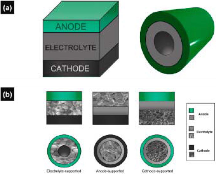
Figure 2. SOFC geometries: (a) 3D model of the planar and tubular cell, (b) cross-sections of electrolyte-, anode-, and cathode-supported cells for both planar and tubular geometry (Zarabi et al., 2022).
Electrolyte-supported and anode-supported cells are two common configurations used in SOFC design, each with distinct characteristics that impact performance and application suitability. Electrolyte-supported cells typically employ a thick ceramic electrolyte, such as YSZ, to provide mechanical stability, while the electrodes are deposited as thin functional layers. The main advantage of this design is structural robustness and thermal uniformity, but the thick electrolyte contributes to higher ohmic resistance and operating temperatures (typically 900 °C–1,000 °C), limiting efficiency and start-up speed (Mendonça et al., 2021; Mahato et al., 2015). In contrast, anode-supported cells feature a thick porous anode layer, which serves as the mechanical backbone, allowing the electrolyte to be much thinner. This results in significantly reduced ohmic losses and enables operation at intermediate temperatures (700 °C–800 °C) with faster start-up and better thermal cycling behavior (Hussain and Yangping, 2020; Lyu et al., 2020). However, anode-supported cells may suffer from mechanical fragility due to the porous structure and are more susceptible to redox cycling damage. Table 1 shows the detailed comparison of electrolyte supported vs. anode supported cells, focusing on the their advantages, disadvantages, current status, progress, and future directions.
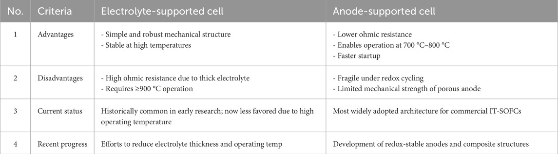
Table 1. Detailed comparison of electrolyte supported vs. anode supported cells.
The flat-tube configuration presents an alternative geometry for SOFC stacks, merging the advantages of both tubular and planar SOFCs. It offers easier sealing compared to planar designs and facilitates uncomplicated cell stacking. Moreover, it is more resilient to thermal stress than tubular configurations and boasts a higher specific volumetric power. Nonetheless, manufacturing flat-tube SOFCs is more challenging and expensive compared to planar cells (Kuterbekov et al., 2022).
2.4 From cell to stack
A single cell can function independently to produce an electric current or voltage and serves as the fundamental building block for creating more powerful and complex systems known as “stacks.” A stack is formed by connecting multiple cells in series. Each unit cell consists of two porous layers, the anode and cathode, separated by a dense electrolyte layer. When assembling multiple cells into a stack, an interconnect is required, and a sealant may also be used to prevent the mixing of fuel and air (Abdalla et al., 2020). This is particularly important in planar SOFC designs, the most widely studied type, as they offer higher power density and can be optimized to reduce the risk of reoxidation in anode-supported cells (Mendonça et al., 2021).
2.5 Stack durability and degradation mechanisms
The durability of SOFC stacks is a key performance metric that determines their viability in long-term applications, especially for stationary power generation, auxiliary power units, and distributed energy systems. While SOFCs offer high efficiency and fuel flexibility, their commercial competitiveness depends heavily on their ability to maintain electrochemical performance over 40,000 h of continuous operation under thermal and chemical stress (Stambouli and Traversa, 2002). Stack durability is influenced by thermal cycling, fuel quality, and load transients. Rapid temperature changes can lead to mechanical stress, seal failure, and delamination. Advanced material design (e.g., compliant seals, graded electrodes), improved balance-of-plant (BoP) control, and system-level thermal management are essential to minimize these effects.
Stack degradation arises from several interrelated mechanisms affecting each component, including anode, cathode, electrolyte, interconnects, and seals, under high operating temperatures (600 °C–900 °C). One of the primary causes of performance loss is anode degradation, including Ni coarsening, sulfur poisoning, carbon deposition, and redox cycling damage. Ni coarsening reduces active surface area for fuel oxidation, while redox cycling during shutdown/startup induces volume changes and mechanical damage, especially in anode-supported designs. Cathode degradation is often driven by strontium segregation in perovskite materials like LSCF and BSCF, leading to reduced oxygen reduction kinetics and poor surface exchange. Additionally, interfacial reactions between the cathode and electrolyte can form insulating secondary phases, such as La2Zr2O7, especially when YSZ is used. Electrolyte degradation, while generally less severe, may include grain boundary resistance and electrolyte-electrode delamination under thermal cycling. Another major contributor to stack degradation is the metallic interconnect, which suffers from chromium volatilization oxide scale growth. Chromium species can migrate and poison the cathode, lowering ORR activity (Zarabi et al., 2022; Sreedhar et al., 2020). To mitigate this, protective coatings such as MnCo2O4 or conductive ceramic layers are often applied (Bianco et al., 2019). To improve durability, ongoing research focuses on developing stable electrode materials, sulfur- and redox-tolerant anodes, infiltrated cathodes, and high-temperature corrosion-resistant interconnects.
2.6 Anode gas recycle in SOFC systems
Anode gas recycling (AGR) is an increasingly studied approach in SOFC systems designed to improve fuel utilization, thermal efficiency, and system integration. In this configuration, a portion of the anode exhaust, containing unreacted hydrogen, steam, carbon monoxide, and carbon dioxide, is recycled back to the anode inlet, typically after passing through a heat exchanger and gas conditioning system. In contrast, conventional SOFCs without AGR discharge all anode off-gas to a burner or exhaust treatment system. The inclusion of AGR offers several benefits. First, the recycled gas preheats incoming fuel and provides additional steam, reducing or even eliminating the need for external steam injection in systems using hydrocarbon fuels. This leads to enhanced reforming efficiency, improved hydrogen yield, and reduced system complexity. Moreover, AGR enhances fuel utilization, which translates directly into higher electrical efficiency. AGR also improves temperature uniformity in the anode, helping mitigate thermal gradients and hotspots that can accelerate material degradation. These effects not only increase fuel conversion efficiency but also extend cell lifetime by reducing redox cycling and localized degradation. Additionally, the presence of steam and residual H2 in the recycled stream can help suppress carbon deposition, particularly in methane-fueled systems operating under internal reforming (Wei et al., 2025; Li et al., 2018).
However, AGR introduces new challenges. The recycled gas typically has a lower hydrogen partial pressure, which can reduce the Nernst potential and lower open-circuit voltage (OCV). System design must carefully balance recycling ratio, anode gas composition, and flow distribution to avoid significant performance losses. Moreover, accumulation of inert species such as N2 or CO2 in the loop can dilute the fuel stream, reducing reforming kinetics and cell efficiency, especially during long-term operation (Halinen et al., 2012).
From a control perspective, AGR systems are also more complex, requiring additional pumps, valves, and heat exchangers, which increase parasitic power consumption and capital cost. Nevertheless, when properly integrated, SOFCs with anode gas recycle can offer notable system-level advantages in terms of fuel flexibility, efficiency, and thermal integration, especially in CHP or microgrid applications where waste heat and high fuel utilization are critical.
3 Fuel preparation for SOFC
3.1 Fuel utilization
Fuel preparation is a critical step in solid oxide fuel cell (SOFC) systems, particularly when using hydrocarbon fuels such as natural gas and biogas. A gaseous stream containing impurities such as sulfur-based impurities (e.g., H2S, H2S2, COS, SO2, etc.), which are known to cause rapid catalyst poisoning, especially for Ni-based anodes commonly used in commercial SOFCs. When impurities absorb onto the anode surface, they disrupt the mass transport of fuel molecules, potentially blocking the gas diffusion channels. These impurities also hinder the catalytic activity of Ni in thermochemical and electrochemical reactions and affect the YSZ electrolyte’s ability to transport oxygen ions by forming other phases, such as silicates or zirconium phosphate. Additionally, impurities can alter the electrical conductivity of Ni by forming Ni alloys, impact the anode-interface interconnection conductivity, and compromise the structural integrity of both the Ni-YSZ and sealing materials. Furthermore, interactions between SOFC components and impurities can influence other material properties, such as thermal conductivity, porosity, and elasticity modulus, leading to a reduction in mechanical performance (Corigliano et al., 2022). To mitigate these effects, effective desulfurization techniques must be implemented upstream of the SOFC stack. Two different approaches are commonly investigated for removing sulfur in SOFC fuel processors. In the first approach, desulfurization is performed prior to reforming by selectively adsorbing organosulfur compounds present in fuels. This is typically achieved using high-surface-area adsorbents such as activated carbon or metal oxides. In the second approach, the sulfur-containing fuel is first reformed and the resulting fuel gas, which contains hydrogen sulfide (H2S), is then purified by adsorptive removal of H2S using metal oxide sorbents such as ZnO (Krumpelt et al., 2002) Pre-reformer desulfurization is effective for fuels with stable sulfur compounds, while post-reformer cleanup is favored for handling dynamic sulfur release and reformer compatibility.
Fuel can be supplied for SOFCs either directly or indirectly. In direct utilization, the fuel is fed straight into the SOFC system, allowing it to reach the electrochemical active sites at the anode and undergo electrochemical oxidation facilitated by catalytic properties. At high operational temperatures, fuel such as hydrocarbons in natural gas are prone to decompose into lighter hydrocarbons or hydrogen before reaching these active sites, a process facilitated by the presence of catalyst at the anode (Badwal et al., 2015; Xu et al., 2022). Additionally, steam or dry reforming of hydrocarbons may occur. Besides direct utilization, fuel can be utilized in SOFCs through other indirect modes, such as external reforming and internal reforming, as shown in Figure 3. External reforming involves separate units for the fuel cell reaction and the reforming process, while internal reforming includes both processes in the same apparatus.
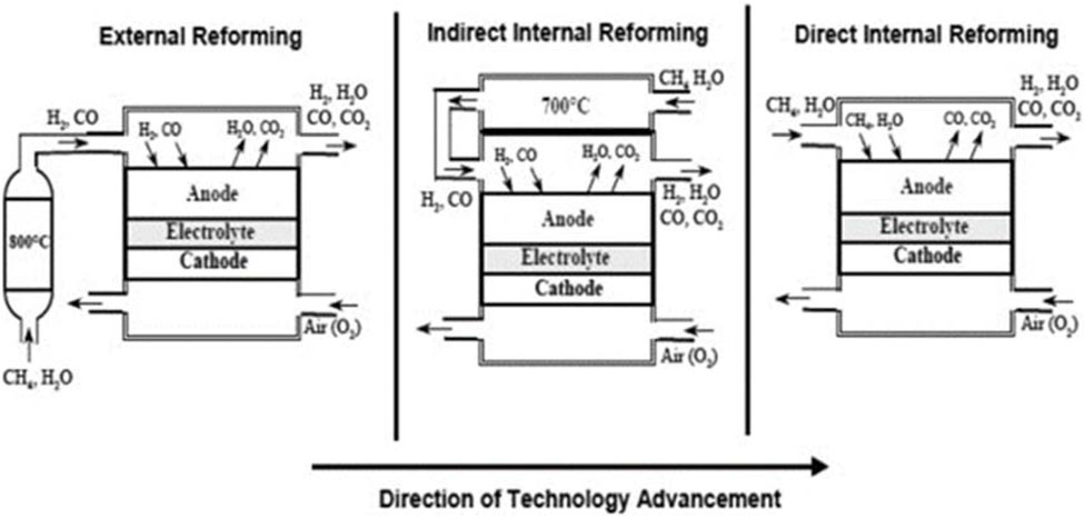
Figure 3. SOFC-reformer configuration (Choudhury et al., 2013).
Natural gas is a popular fuel for SOFC due to its accessibility, affordability, and high energy density. It is converted to hydrogen and carbon monoxide through the steam methane reforming (SMR) process, where hydrocarbons react with steam at high temperatures catalytically. The process produces more hydrogen via the water-gas shift reaction. The SMR process is illustrated for methane, as follows:
Steam methane reforming:
Water - gas shift (WSH) reaction:
Two methods are used to generate reforming steam for the SMR process: recirculating anode exit gas or using a Heat Recovery Steam Generator (HRSG) with pressurized demineralized water. Ejectors or high-temperature blowers recycle some of the SOFC’s anode compartment steam for the first method, while the second approach uses an HRSG to generate reforming steam from exhaust gases, making it easier to monitor and control steam production for thermal purposes (Damo et al., 2019; Buonomano et al., 2015). Additionally, since the SMR process is endothermic, heat must be supplied to the reforming chamber, leading to increased costs and system complexity. Consequently, external reforming is typically suitable only for large-scale stationary SOFCs, often in combination with combined heat and power (CHP) applications. For small-scale devices, particularly portable or transport systems, internal reforming processes may be more desirable, as they allow for heat utilization from the cell stack through radiation or direct contact (Choudhury et al., 2013; Xu et al., 2022).
Modern solid oxide fuel cell (SOFC) systems increasingly adopt direct internal reforming (DIR) to simplify system architecture and enhance overall thermal efficiency. In DIR configurations, hydrocarbon fuels, most commonly methane or natural gas, are reformed directly within the anode compartment of the SOFC stack, thereby eliminating the need for an external reformer. This approach leverages the endothermic nature of reforming reactions, which absorb the waste heat generated by electrochemical oxidation, resulting in improved heat integration and fuel utilization (Alaedini et al., 2023; Faheem et al., 2022). The current advancements in catalyst design and process upgrading for steam methane reforming (SMR) relevant to SOFCs are comprehensively reviewed by Zhang et al. (2021).
Several companies, including Bloom Energy, Convion, Mitsubishi Power, and Ceres Power, have successfully implemented DIR in commercial or pre-commercial SOFC systems. These systems often employ Ni-based anodes optimized for catalytic activity and fuel distribution, with careful control of temperature gradients to prevent carbon deposition. While DIR reduces the need for external reformers and associated complexity, it also increases the demand for precise thermal management and fuel composition control, especially in the presence of sulfur compounds or heavier hydrocarbons. To address these challenges, hybrid designs combining partial external reforming with DIR, as well as the use of sulfur-tolerant materials and graded anode structures, are actively being pursued. Ultimately, careful selection of operating conditions, flow field designs, and anode materials is required to mitigate risks such as carbon deposition, sulfur poisoning, and local overheating, factors that can otherwise lead to irreversible degradation of cell performance.
Renewable resources such as biomass can be utilized as fuel for SOFCs. However, these fuels must first be converted to hydrogen and carbon monoxide using either external or indirect internal reforming methods as shown in Figure 3. Given that the indirect internal reforming process is more suitable for small-scale applications, the focus of the next section will be on the external reforming process for producing hydrogen from biomass.
3.2 Hydrogen production from biomass
Hydrogen production from biomass represents a promising pathway for sustainable energy generation, leveraging the renewable nature of biomass feedstocks such as agricultural residues, forestry by-products, and organic wastes. The conversion of biomass to hydrogen can be achieved through thermochemical and biochemical processes. Although biological processes are environmentally friendly and operate under mild conditions, making them less energy-intensive, they generally yield low hydrogen production rates and efficiencies, which vary depending on the raw materials used. In contrast, thermochemical processes are significantly faster and provide higher yields of hydrogen, with gasification being particularly advantageous from both economic and environmental perspectives (Nikolaidis and Poullikkas, 2017). The biological hydrogen production was comprehensively reviewed in (Akhlaghi and Najafpour-Darzi, 2020). In the next sections, the hydrogen from thermochemical processes will be briefly discussed.
3.2.1 Hydrogen from biomass gasification
Biomass gasification is an efficient and sustainable method that involves the thermochemical conversion of biomass materials into hydrogen-rich syngas. This process occurs in a gasifier, where biomass feedstocks such as agricultural residues, wood chips, and organic waste are subjected to high temperatures (700 °C–1,000 °C) in the presence of a controlled amount of air, oxygen or steam. Fixed bed, fluidized bed and indirect gasifiers are the three main types of reactors used for biomass gasification, the most common configurations, as shown in Figure 4.
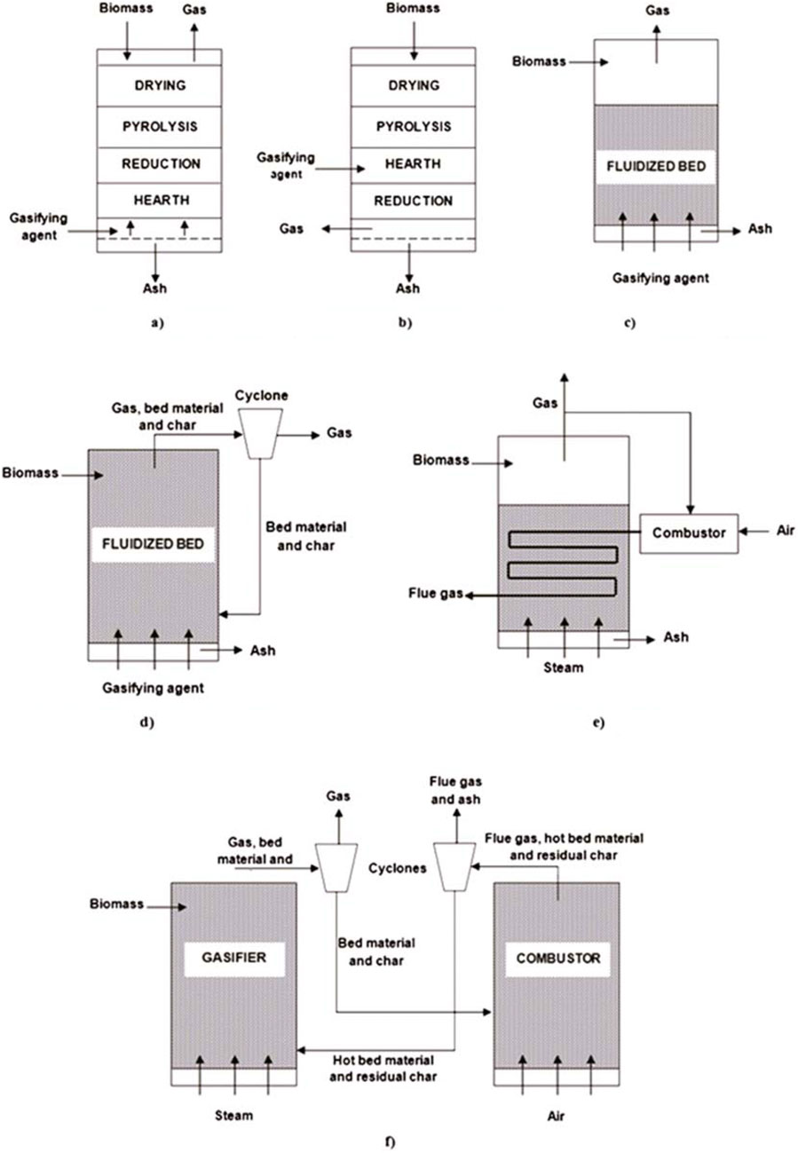
Figure 4. Gasifier configuration (Iribarren et al., 2014). (a) Updraft fixed bed gasifier. (b) Downdraft fixed bed gasifier. (c) Bubbling fluidized bed gasifier. (d) Circulating fluidized bed gasifier. (e) Gas indirect gasifier. (f) Char indirect gasifier.
The generalized biomass gasification reaction can be represented as in Equation 3 (Corigliano et al., 2021):
Subsequent steam reforming and water-gas shift reactions further enhance the hydrogen content by converting carbon monoxide and water into additional hydrogen and carbon dioxide, as shown in Equations 1, 2 respectively.
This method offers several advantages, including the ability to utilize diverse and abundant biomass resources, reducing dependence on fossil fuels, and contributing to carbon neutrality when sustainably sourced biomass is used. Notably, when coupled with SOFCs, wet residual biomass can be also used as a primary feedstock for gasification (Prestipino et al., 2025). However, challenges remain in optimizing gasifier design, improving gas cleanup processes to remove tar and other contaminants, and enhancing overall efficiency and scalability. Advances in catalyst development, process integration, and waste heat recovery are crucial for making biomass gasification a commercially viable and environmentally friendly pathway for hydrogen production.
3.2.2 Hydrogen from biomass pyrolysis
Biomass pyrolysis is an emerging thermochemical process that involves the thermal decomposition of biomass in the absence of oxygen to generate a range of products, including liquid products (tar and bio-oil), syngas, and biochar, as expressed in Equation 4 (Abi Bianasari et al., 2024; Hoang et al., 2024). During pyrolysis, biomass is heated to temperatures typically between 400 °C and 600 °C, resulting in the breakdown of complex organic molecules. The resultant syngas, composed mainly of hydrogen, carbon monoxide, methane, and other light hydrocarbons, can be further processed to increase hydrogen yield. The steam reforming and water-gas shift reactions of the syngas itself is one common approach to produce additional hydrogen.
Bio-oils are divided into two categories: water-soluble oils and water-insoluble oils, where the water-soluble oils are specifically employed for hydrogen production (Hosseini and Wahid, 2016). Due to the high oxygen content and significant presence of heavy fractions, enhancing the quality and economic value of tar through upgrading has become a significant focus (Zhao et al., 2019). Research has explored the use of catalysts such as ZSM-5 zeolite-based catalysts (Zhao et al., 2019; Ren et al., 2018; Yang et al., 2019) and Ni-based catalysts (Chen et al., 2019; Hu et al., 2018; Waheed et al., 2016) for decomposing the heavy hydrocarbons in tar during pyrolysis. Furthermore, additional hydrogen can be produced through steam reforming and the water-gas shift reaction.
The pyrolysis process can be categorized into fast pyrolysis and slow pyrolysis based on operating conditions. Fast pyrolysis, which occurs at high temperatures and very short residence times, is favored for hydrogen production. In contrast, slow pyrolysis is generally not considered for hydrogen production due to its primary output of charcoal. Fast pyrolysis reactors can be classified into four types: ablative, fluidized bed, circulating fluidized bed, and entrained flow. To enhance hydrogen production from biomass pyrolysis, fluidized catalyst beds are employed to address the issue of rapid catalyst deactivation caused by significant coking and char deposition on the catalyst surface (Hosseini and Wahid, 2016). Figure 5 illustrates a provides a schematic diagram of biomass fast pyrolysis for hydrogen production.
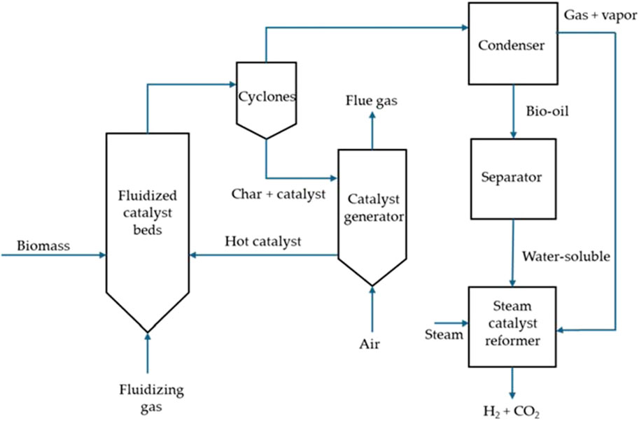
Figure 5. Biomass fast pyrolysis process for hydrogen production.
4 Current SOFCs applications for stationary power generation
SOFCs are a highly efficient and environmentally friendly option for power generation. They can be used either as independent power generators or in conjunction with traditional power plants. The three main applications of SOFCs are in combined cycle power plants, cogeneration/trigeneration, and residential settings. Table 2 shows the comparison of SOFC applications for power generation.
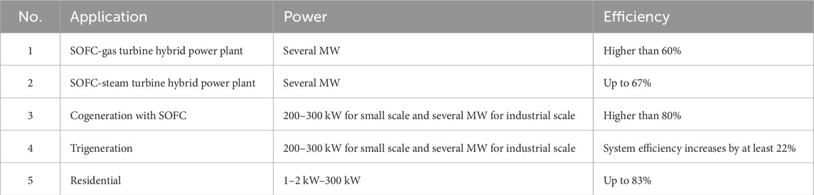
Table 2. SOFC applications for power generation (Bianco et al., 2019).
4.1 Combined cycle power plant with SOFC
SOFCs are highly efficient energy conversion devices that generate electricity through electrochemical reactions, typically involving fuels such as hydrogen or natural gas. To further enhance the efficiency of SOFC systems, especially in stationary power generation applications, they are often integrated with various thermodynamic cycles which optimize the use of heat and energy produced by SOFCs, leading to improved overall efficiency, reduced fuel consumption, and lower greenhouse gas emissions. Thermodynamic cycles for power generation can be structured variously based on its economics, thermal performance, and the operating conditions (Yu et al., 2015). These cycles generally are divided into two main groups based on the working medium: steam power cycle and gas power cycle.
The Brayton cycle, commonly used in gas turbines, is one of the most frequently integrated thermodynamic cycles with SOFC systems (Corigliano et al., 2022). In an SOFC-Brayton hybrid system, the high-temperature exhaust gases from the SOFC are used to drive a gas turbine, which generates additional electricity. This process not only recovers energy from the waste heat but also enhances the overall efficiency of the power generation system. The integration of the Brayton cycle with SOFCs can lead to efficiencies exceeding 60%, making it a popular choice for high-performance stationary power plants (Damo et al., 2019).
The Rankine cycle, which is the basis for most steam turbine systems, is another thermodynamic cycle often coupled with SOFCs. In an SOFC-Rankine hybrid system, the heat from the SOFC’s exhaust is used to generate steam, which then drives a steam turbine to produce extra electricity. This cycle is particularly effective in utilizing the residual heat from the SOFC, which operates at high temperatures (typically around 800-1,000 °C) (Yu et al., 2015). The combination of SOFC and Rankine cycle can achieve high overall efficiencies and is suitable for large-scale stationary power generation.
The Kalina cycle, although less common than Brayton or Rankine cycles, offers a unique approach to improving SOFC system efficiency. It uses a mixture of water and ammonia as the working fluid, which allows for better thermal efficiency at lower temperatures compared to traditional Rankine cycles (Yu et al., 2015). When integrated with SOFCs, the Kalina cycle can effectively utilize the lower-grade heat from the exhaust gases, making it a promising option for enhancing the overall efficiency of SOFC-based power generation systems.
Organic Rankine cycles (ORCs) are regarded as an excellent choice when the heat source temperature is in the low-to-moderate range from 80 °C to 300 °C (Muñoz et al., 2022). These cycles use organic fluids that can condense at pressures above ambient and have low boiling points, making them well-suited for operation under lower temperature and pressure conditions. ORCs can efficiently operate in either subcritical or trans-critical cycles, depending on the organic fluid selected.
4.1.1 SOFC-gas turbine hybrid power plant
The concept behind a SOFC-gas turbine (SOFC-GT) hybrid cycle is to use a SOFC stack in a pressurized Brayton cycle instead of a combustor to generate energy and heat the stream used to expand the turbine (Buonomano et al., 2015). Two integration methods are available: direct or indirect. In the direct SOFC-GT hybrid system (Figure 6a), fuel flows into the SOFC anode side, and compressed air is heated by power turbine exhaust gas. The residual anode gases are burned with cathode exhausted air. In contrast, as shown in Figure 6b, the indirect SOFC-GT hybrid system heats air from the compressor using fuel cell exhaust, eliminating the need for a combustor in the gas turbine. However, indirect SOFC-GT integration is rarely used due to material constraints (Choudhury et al., 2013; Mendonça et al., 2021).
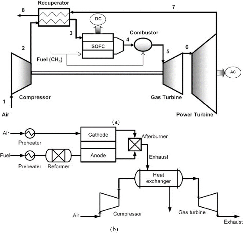
Figure 6. SOFC-gas turbine integration methods: (a) direct integration, (b) indirect integration (Choudhury et al., 2013).
Most research has focused on internally reformed SOFC/GT hybrid cycles due to their efficiency and low capital costs, whereas external reformer systems typically use biogas, syngas, liquids, and other complex fuels that cannot be safely delivered to the SOFC stack (Buonomano et al., 2015). In the study, the internally reformed system absorbed heat directly from the SOFC cathode, while the externally reformed system used a heat exchanger to transfer heat from the SOFC cathode exhaust gases, as shown in Figures 7a, b, respectively. The study found that the internally reformed SOFC/GT demonstrated superior performance when both power plants were operated under identical conditions due to simpler thermal management and better fuel efficiency.
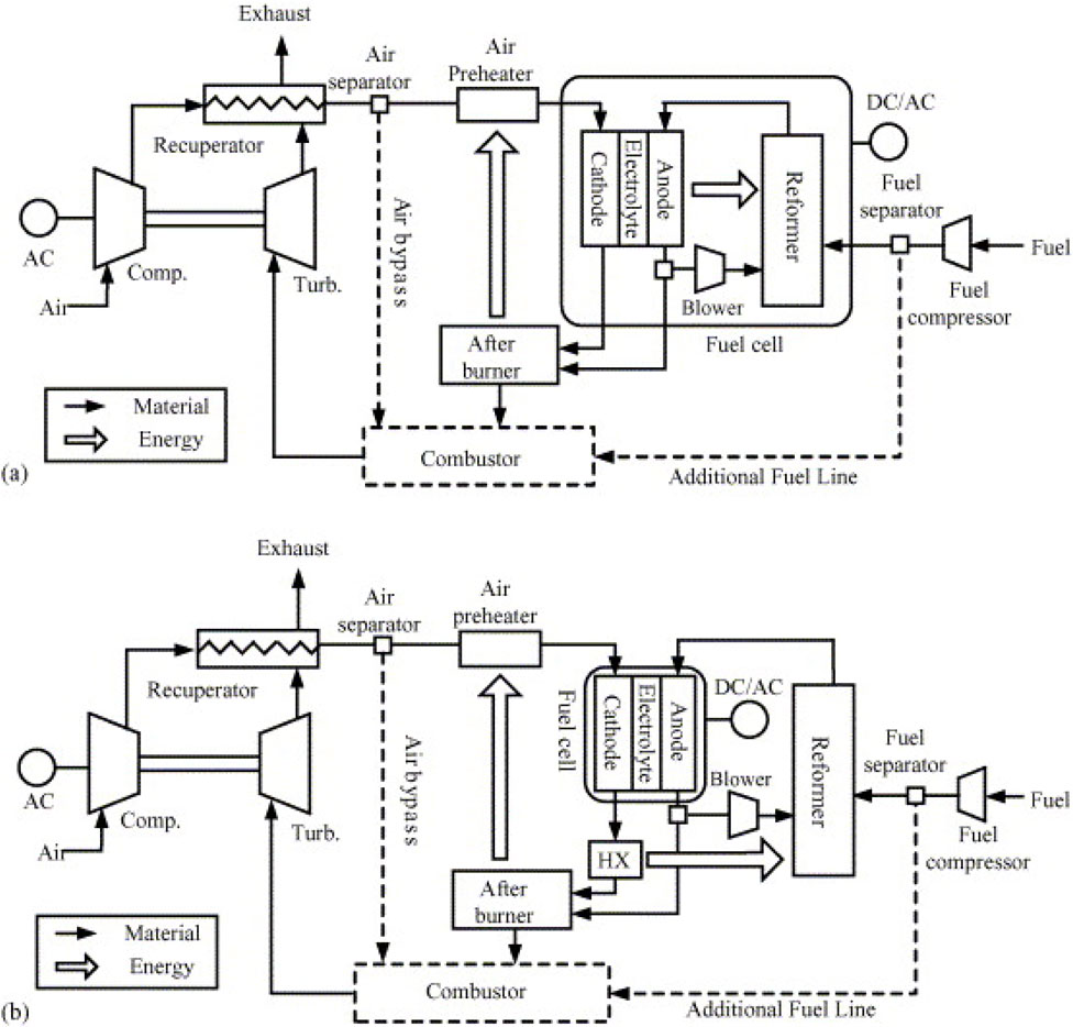
Figure 7. SOFC/GT power plants: (a) Internal reforming, (b) External reforming (Yang et al., 2006).
McLarty et al. (2012) introduced a dynamic model of a 220-kW tubular SOFC/GT hybrid configuration, as depicted in Figure 8. This hybrid setup adopts an indirect internal reforming (IIR) tubular SOFC stack arrangement featuring an anode recirculation ejector. The system comprises three parallel stacks of 384 series connected SOFC cells operating at approximately 1,000 °C. As shown in Figure 8b, positioned between the rows of tubular fuel cells, reformers utilize depleted anode gas for the generation of heat and steam essential for natural gas reformation. Additionally, the system integrates a two-shaft gas turbine configuration, comprising a compressor, high-pressure and low-pressure turbines, and an AC generator. Two combustors are solely engaged during system startup and shutdown phases.
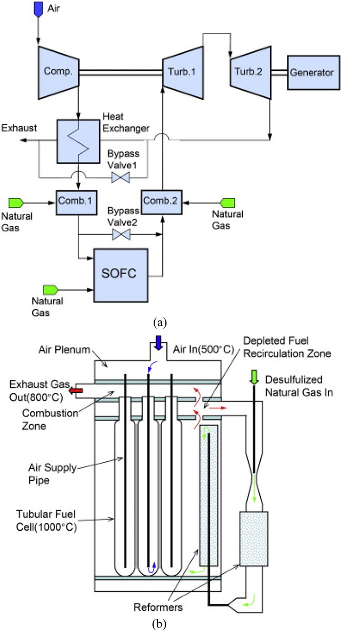
Figure 8. Schematic of the pressurized 220 kW SOFC/GT hybrid system in (McLarty et al., 2012). (a) SOFC/GT hybrid system. (b) The tubular SOFC stack.
Chen et al. (2017) proposed control techniques for a SOFC-GT hybrid system based on the direct internal reforming (DIR) SOFC configuration that recirculates the anode and cathode exhausts to provide steam for the reforming process and preheat the fuel and air, as illustrated in Figure 9. A mixing process combines the fuel with recirculated anode exhaust to elevate its temperature and ensure sufficient steam content, thereby mitigating carbon deposition risks within the reformer and SOFC. The reforming heat exchanger (RHE) facilitates gas reforming and fuel preheating. Simultaneously, the cathode recirculation loop blends pressurized and preheated air with a portion of the cathode exhaust, thus facilitating air preheating. Unreacted fuel from the SOFC enters the afterburner for complete combustion with cathode exhaust, releasing additional heat. The resulting afterburner gas initially heats the RHE before expanding in the turbine to generate power. The efficacy and safety of the SOFC-GT hybrid system are ensured through control loops governing power output, fuel utilization, SOFC temperature, and rotation speed.
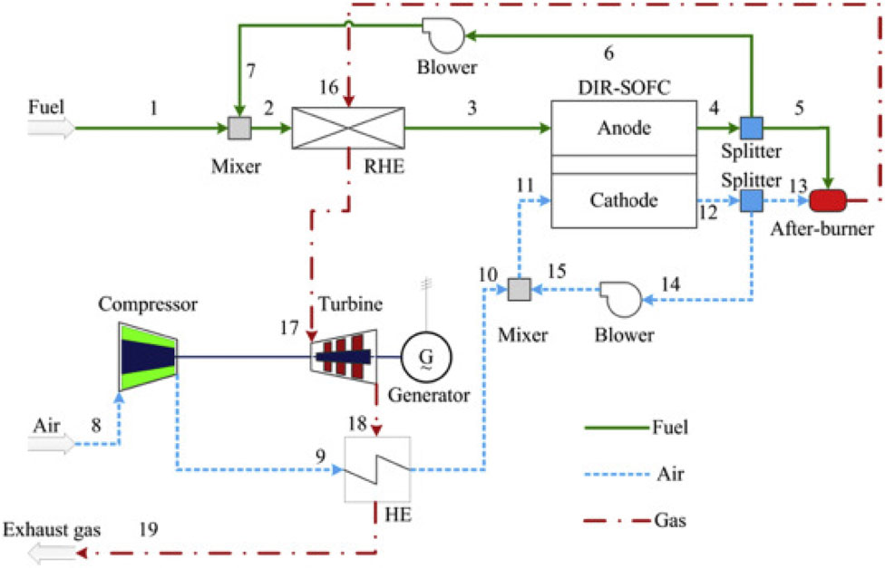
Figure 9. Integration scheme of the SOFC-GT system in (Chen et al., 2017).
Utilizing the waste heat from the high-temperature exhaust of GT in the SOFC-GT hybrid systems presents an opportunity to enhance overall energy efficiency. This can be achieved through the integration of high-temperature fuel cells with various systems such as thermal desalination systems (Najafi et al., 2014; Meratizaman et al., 2014), steam Rankine cycles (Aminyavari et al., 2016), Organic Rankine cycles (Yan et al., 2013), and Kalina cycles (Gholamian and Zare, 2016; Tan et al., 2017).
Najafi et al. (2014) introduced an IRSOFC-GT hybrid configuration coupled with a Multistage Flash (MSF) desalination unit, as depicted in Figure 10, aimed at concurrent energy and freshwater generation. The mixture of sulfur-free fuel and steam is directed into the anode compartment after being combined with the anode recirculation stream. This combined stream undergoes reforming to yield hydrogen-rich products. Air and fuel recuperators process power turbine flue gas (REC 1 & REC 2). The distillation unit relies on saturated steam supplied by the Heat Recovery Steam Generator (HRSG). A similar hybrid system of SOFC-GT with MSF desalination unit was presented by Meratizaman et al. (2014).
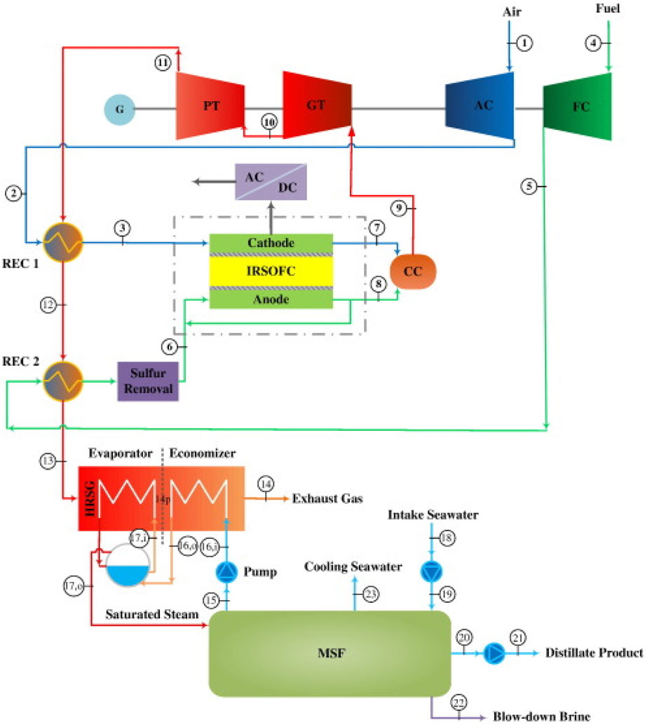
Figure 10. Schematic diagram of IRSOFC–GT hybrid cycle coupled to MSF desalination system in (Najafi et al., 2014).
Aminyavari et al. (2016) presented an IRSOFC-GT hybrid setup combined with a steam Rankine cycle, illustrated in Figure 11, where the layout closely resembles the configuration investigated by Zarabi et al. (2022). In this arrangement, power generation within the steam Rankine cycle is facilitated through steam obtained from the heat recovery steam generator.
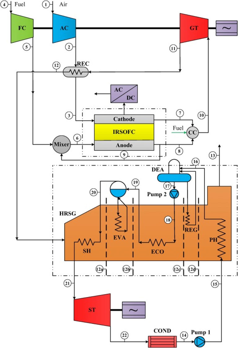
Figure 11. Schematic diagram of the SOFC-GT cycle coupled with a Rankine bottoming cycle in (Aminyavari et al., 2016).
Yan et al. (2013) evaluated the integration of Organic Rankine cycles (ORC) with the IRSOFC-GT cycle, employing Liquefied Natural Gas (LNG) as a thermal sink to recover its cryogenic energy, as depicted in Figure 12. Exhaust gases from the gas turbine are utilized to warm incoming air and fuel for the SOFC, subsequently generating steam for internal reforming processes. Eventually, these exhaust gases are directed to a waste heat boiler to release waste heat to the organic working fluid within the ORC subsystem. This configuration effectively lowers the condensing temperature of the ORC by utilizing LNG expansion cooling.
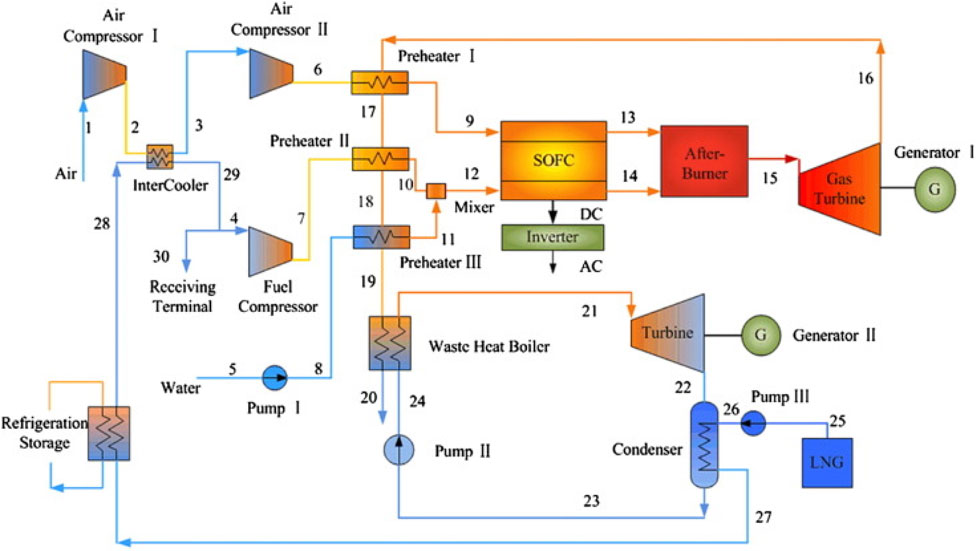
Figure 12. SOFC/GT–ORC system layout in (Yan et al., 2013).
Gholamian and Zare (2016) employed Organic Rankine and Kalina cycles to recover waste heat from SOFC/GT systems, as shown in Figure 13. The Kalina Cycle (KC) utilized an ammonia-water mixture instead of a pure fluid. In the depicted setup, exhaust gases from the hybrid SOFC/GT system are directed into the evaporators of both the ORC and KC, supplying thermal energy for the evaporation of the working fluid. The authors observed superior performance of the ORC compared to the Kalina cycle. The combined SOFC/GT-ORC system achieved an exergy efficiency of 62.35 percent, while the GT-KC system achieved 59.53 percent.
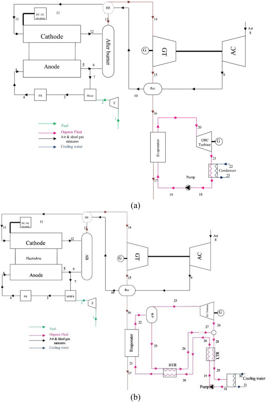
Figure 13. Schematic diagram of: (a) SOFC/GT-ORC, (b) SOFC/GT-KC in (Gholamian and Zare, 2016).
4.1.2 SOFC-steam turbine hybrid power plant
While hybrid SOFC/gas turbine systems have received significant attention in research, the literature on SOFC/steam turbine (SOFC/ST) systems is quite limited. Rokni (2010) lays out a typical hybrid SOFC-steam turbine system. The unit has a desulfurization reactor and pre-reformer. After the heavier hydrocarbons are broken down in the pre-reformer, they are sent to the desulphurized reactor to be removed. The SOFC’s anode receives the fuel after it has been processed. Any unburned fuel after the SOFC stacks is sent to the burner. Heat recovery steam generators (HRSGs) use the exhaust gases in a Rankine cycle to generate steam, as seen in Figure 14. All the standard components of a Rankine plant are here: a condenser, a steam generator to create steam for the steam turbine, and a suction pump to draw in the working fluid at the end of the cycle. The author analyzed two scenarios in which natural gas was used as a feedstock for a SOFC/ST system that first underwent steam reforming and partial catalytic oxidation. Based on the findings, the system’s electric efficiency for fuel processors has the potential to reach 62%.
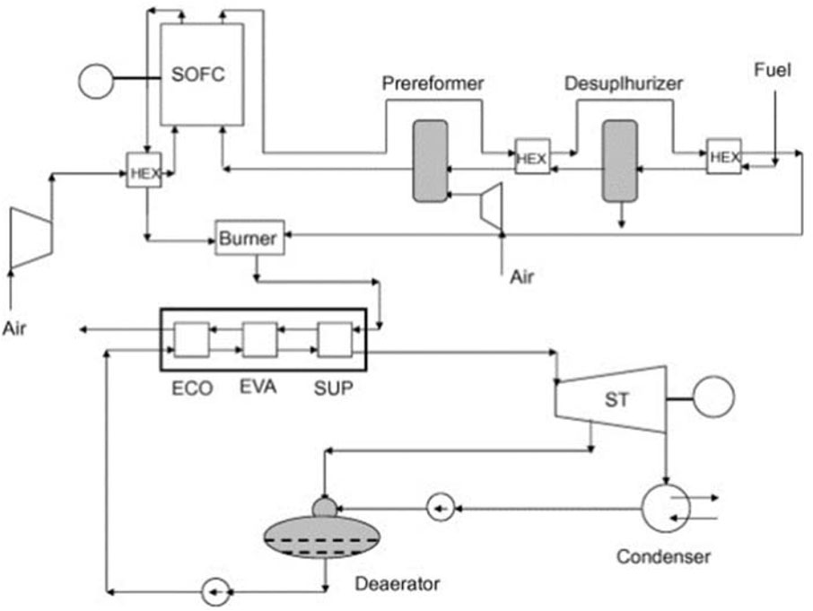
Figure 14. A typical SOFC/ST power system scheme (Rokni, 2010).
Ugartemendia et al. (2013) introduced and investigated the optimal operational parameters for a hybrid system combining a solid oxide fuel cell (SOFC) and a steam turbine (ST), powered by hydrogen (depicted in Figure 15). The proposed configuration utilizes the excess heat generated by the SOFC to drive a bottoming cycle (BC) using steam turbine. Preheating of the SOFC’s hydrogen and air inputs is achieved through two parallel heat exchangers (HE1 and HE2). Additionally, heat from the hot box is transferred to the bottoming cycle via HE3. A steam turbine coupled with a synchronous generator is employed to convert the recovered waste heat into electricity. The authors suggest that this technology could be integrated into renewable energy systems, such as wind farms, enhancing overall reliability. Hydrogen produced during off-peak periods could then be utilized to power the fuel cell component of the hybrid system.
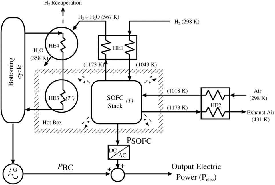
Figure 15. The proposed hybrid SOFC-ST system in (Ugartemendia et al., 2013).
4.2 Cogeneration/trigeneration with SOFC
4.2.1 Cogeneration
The term cogeneration refers to a process in which mechanical and thermal energy are produced from a single primary energy source. Mechanical energy can drive an electric alternator or other rotating machinery such as motors, compressors, pumps, or fans. Various direct and indirect applications of thermal energy, including steam generation, hot water, hot air for drying processes are feasible. The high-temperature flue gas from SOFCs can be utilized for space heating or to generate steam within the Rankine cycle. It can also be employed in energy-intensive equipment like preheaters and reformers to heat the air before combustion. Consequently, SOFC systems have the capability to cogenerate heat alongside electrical energy. This process can be also called the combined heat and power (CHP).
Lee et al. (2014) conducted an investigation into a CHP system based on external reformer SOFC technology, which integrates simultaneous generation of electricity and steam. Figure 16 shows a schematic representation of the system in the study. The SOFC stack exhibits a power output of 100 kW, operating under atmospheric pressure and at a temperature of 850 °C. In this setup, an external reformer receives heated fuel and water via a heat exchanger (HEX1). The syngas mixture undergoes partial reforming within the external reformer before being conveyed to the anode of the SOFC stack. Within the anode of the SOFC stack, the remaining unreformed fuel undergoes reforming, facilitated by the heat generated by the SOFC stack itself. Subsequently, the unreacted syngas is directed to a catalytic combustor. The exhaust gases emanating from both the solid oxide fuel cell and the catalytic combustor are utilized to heat the incoming air, which, in turn, preheats the fuel and water. The residual thermal energy is recuperated through a heat recovery steam generator (HRSG), leading to the production of steam.
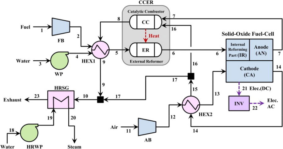
Figure 16. The schematic diagram of the SOFC-based combined heat and power generation system in (Lee et al., 2014).
Yari et al. (2016) introduced two cogeneration systems based on SOFCs, aimed at concurrently producing electricity and providing heating, utilizing biogas sourced from a digester and biomass gasifier, as depicted in Figure 17. The systems incorporate fuel and air heat exchangers to preheat the respective inputs. Preheated air is directed towards the cathode of the stack, while the anode stream undergoes recycling, with biogas/syngas being directed therein. Through an internal reforming process, hydrogen-rich products are introduced into the fuel cell stack, constituting a vital part of the electrochemical reaction. The output of the SOFC stack is converted to usable grid-grade energy via an inverter. A part of the thermal energy generated by the electrochemical reaction is utilized to facilitate the internal reforming process. Excess air and unreacted fuel undergo combustion at elevated temperatures in an afterburner. The resultant heat from the afterburner is employed in a predetermined sequence to warm both fuel and air. The exhaust, retaining sufficient heat, can potentially be utilized to generate steam.
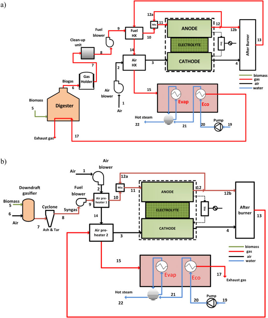
Figure 17. Schematic diagram of CHP system based on (a) digester coupled SOFC, (b) gasifier coupled SOFC (Yari et al., 2016).
Rokni (2014) investigated a combined heat and power (CHP) system incorporating a small-scale integrated SOFC and a Stirling engine with a net electrical capacity of 120 kWe, depicted in Figure 18. This system integrates a biomass gasification facility as a fuel source for SOFC. Essential to the SOFC topping cycle is the compression and heating of surrounding air to reach the cathode inlet temperature. Concurrently, the anode side employs a methane generator to enhance the molar proportion of CH4 in the fuel. Reformation elevates the fuel temperature before entering the catalytic burner, consequently enhancing combustion temperature and thereby increasing the heat available to the Stirling engine. Drawing heat from the exhaust of a catalytic burner, the Stirling engine utilizes household water as a heat sink.
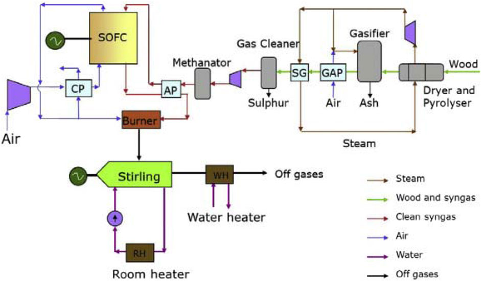
Figure 18. System layout for the integrated SOFC–Stirling-based CHP plant in (Rokni, 2014).
Habibollahzade et al. (2018) also examined the feasibility of a CHP system integrating a SOFC with a Stirling engine. Three distinct gasification and SOFC-based models were proposed in this study, as seen in Figure 19. In Model (a), the biomass gasifier is integrated directly with the SOFC. Model (b) utilizes the off-gases generated by Model (a) in a Stirling engine (SE) to enhance output and efficiency. Model (c) employs a proton exchange membrane electrolyzer (PEME) to produce hydrogen using surplus electricity generated by the SE. Following fuel preparation by the gasifier for the SOFC, the SE functions as the primary electricity and hot water generator, utilizing waste heat from the SOFC. Utilizing the off-gases from the SOFC as a heat source, given their suitable temperature for exploitation in the SE, contributes to this process. A room heater is employed to heat water for domestic use. The PEME utilizes solar energy for hydrogen production. In the evaluation of the proposed models, considerations include energy, exergy, exergoeconomic, and environmental impacts. Results indicated that the energy efficiency of models (a), (b), and (c) ranges from 28.51% in the worst-case scenario to 39.41% in the best-case scenario.
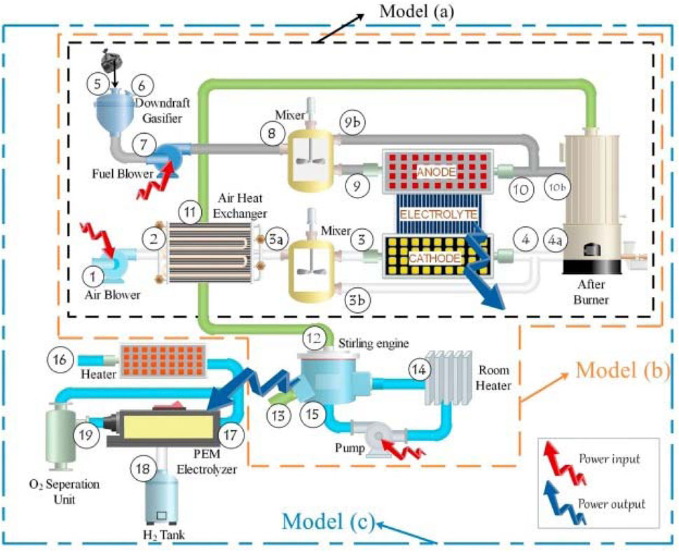
Figure 19. Schematic diagram of the proposed systems in (Habibollahzade et al., 2018).
4.2.2 Trigeneration
The adoption of trigeneration, a method encompassing combined heating, cooling, and power generation (CCHP), is gaining momentum for its environmentally friendly and efficient production of electricity. Trigeneration involves the simultaneous generation of thermal energy and electrical power from a singular fuel source. Additionally, methods such as absorption or desiccant cooling can be integrated to provide cooling, consequently reducing the electricity demand typically associated with conventional air conditioning systems (Choudhury et al., 2013).
Ozcan and Dincer (2015) proposed a trigeneration system based on IRSOFCs, as depicted in Figure 20. This system creates energy through both SOFC and Organic Rankine Cycle (ORC) systems, provide domestic hot water via the ORC condenser, and cool indoor spaces via an air conditioning (AC) system. The high waste heat temperature of SOFC is utilized for air preheating and ORC cycle employing toluene as the working fluid, and the generator of the absorption chiller cycle.
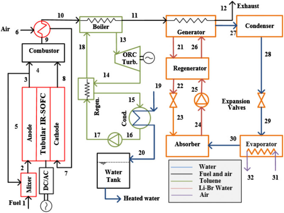
Figure 20. Schematic of the proposed trigeneration system with SOFC in (Ozcan and Dincer, 2015).
Tian et al. (2018) suggested a unique trigeneration system using a SOFC system, an Organic Rankine Cycle (ORC), and an ammonia-water absorption chiller with a CO2 collection system, as shown in Figure 21. Within the SOFC, the exhaust gas from the anode is combusted with pure oxygen instead of air. Utilizing the waste heat from the exhaust gas, power, heat, and cooling can be generated by sequentially connecting an ORC and a chiller heat recovery system on the cathode side. According to the computational analysis, the integrated system exhibits a potential net electrical efficiency and exergy efficiency of up to 52.83% and 59.96%, respectively. The trigeneration efficiency of the combined system is 74.28% without CO2 capture, while with CO2 capture, it is slightly reduced to 72.23%.
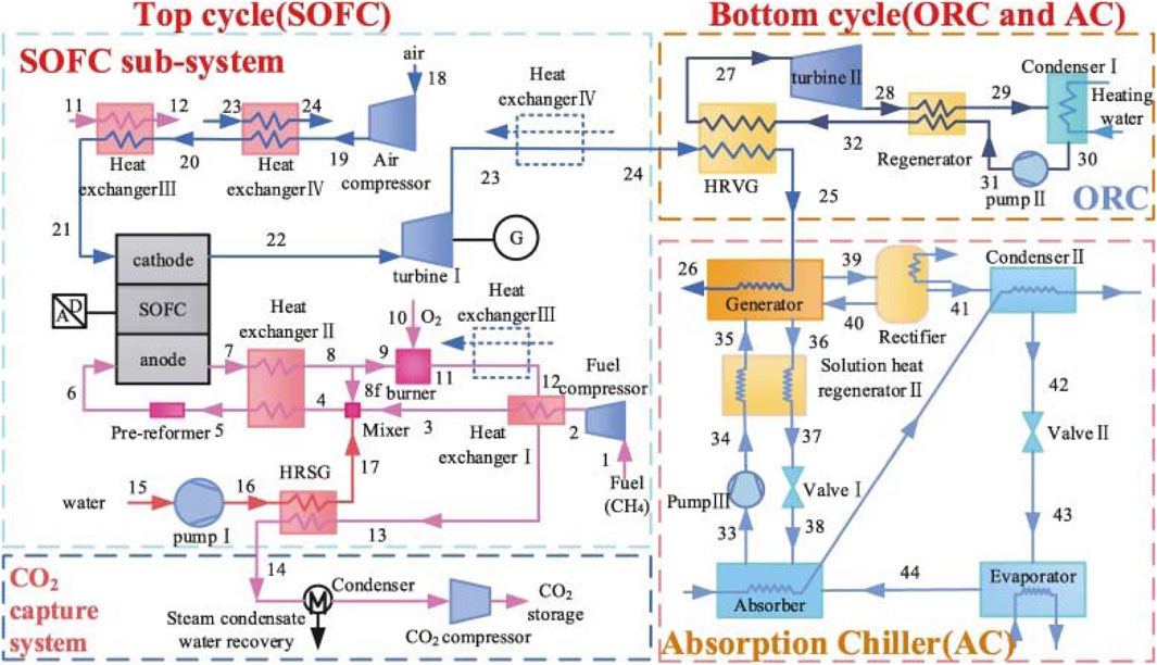
Figure 21. Schematic of the proposed trigeneration system based on the SOFC-ORC-AC system in (Tian et al., 2018).
Baghernejad et al. (2016) conducted a comprehensive exergoeconomic analysis comparing three innovative trigeneration systems utilizing SOFC, biomass, and solar energies integrated with a combined cycle (CC) consisting of a Gas Turbine (GT) cycle and a steam Rankine cycle, as illustrated in Figure 22. Each system employs a combined cycle (CC) as the primary electricity generator, a single-effect absorption chiller for cooling requirements, and a heat exchanger to fulfill heating demands. Among the investigated systems, the combined SOFC-trigeneration system demonstrated the highest electrical exergy efficiency. The SOFC-trigeneration system exhibited the highest trigeneration exergy efficiency at 64.5%, followed by the integrated biomass-trigeneration system at 60%, and the integrated solar-trigeneration system at 56%.
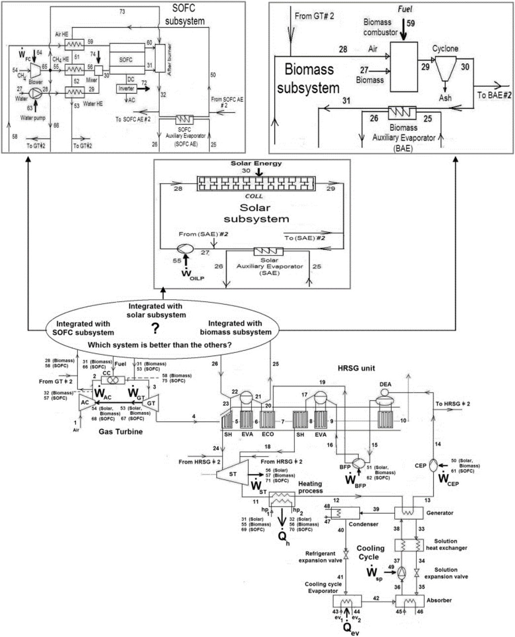
Figure 22. Schematic diagram of the integrated trigeneration plants using the SOFC, biomass and solar subsystems in (Baghernejad et al., 2016).
4.3 Residential applications
Researchers have shown keen interest in employing SOFCs across diverse residential and industrial settings, drawn by their advantageous characteristics, including notably high operating temperature and the high enthalpy of exhaust gases. Further, fuel cells are esteemed for their environmental compatibility, ease of maintenance, fuel flexibility, minimal noise output owing to the absence of mechanical components, and their capability to concurrently generate heat and electricity within the kilowatt to megawatt range (Choudhury et al., 2013).
Facci et al. (2017) introduced a trigeneration power plant based on SOFCs that fulfill the electrical, thermal, and cooling requirements for a small residential community of approximately 10 apartments. The study evaluated various factors including diverse energy demand patterns, electricity tariffs and electric and thermal efficiency of the system. Mehrpooya et al. (2019) conducted a technical examination and assessment of an IRSOFC-based Combined Cooling, Heating, and Power (CCHP) system within the building sector. The system integrates SOFC with a two-stage absorption chiller and a heating system. Utilizing a school building (900 m2) as a case study, they investigated the efficiency of the SOFC-CCHP system in simultaneously generating heat, cold, and power. The net electrical energy efficiency of the 120 kW SOFC was determined to be approximately 45%. The electrical cooling efficiency of the hybrid system stood at 58%, while the electrical heating efficiency reached 60%. Furthermore, the overall efficiency of the CCHP system approached 60%. Economic analysis revealed an anticipated capital recovery period of 8.3 years.
4.4 Industrial development and commercial SOFC systems
The growing global interest in clean and efficient energy solutions has significantly increased industrial investment in SOFC technologies over the past two decades. In recent years, several companies have made notable progress in the commercialization of SOFC technology, effectively translating decades of academic and laboratory-scale development into reliable, market-ready systems. These industrial efforts have advanced SOFC deployment in a range of applications, including distributed generation, combined heat and power (CHP), data center backup, and off-grid microgrids. Below are selected examples of key players and their respective contributions to SOFC commercialization.
Siemens Westinghouse PC (SWPC) was among the early pioneers in commercializing SOFC technology. In the early 2000s, SWPC aimed to demonstrate at least 10 SOFC systems of various sizes. Although some systems were established, they only operated briefly, while others were canceled before installation. These projects included 250 kW atmospheric CHP systems, 1 MW pressurized SOFC/GT hybrid systems, and 125 kW CHP systems (Mendonça et al., 2021).
Kyocera Corporation, a Japanese company that began developing SOFC technologies in 1985 and started mass-producing SOFC cell stacks in 2011, introduced a 3 kW SOFC system for institutional cogeneration, incorporating 700-W cell stacks. Leveraging Kyocera’s ceramic technologies and using city gas as fuel, this system achieves a 52% generation efficiency and a total efficiency of 90% through exhaust heat recovery. Besides efficient power generation, the exhaust heat can be utilized for water heating. This system offers notable energy savings, reduced CO2 emissions, and the ability to adjust power output based on demand, making it superior to traditional cogeneration systems (Mendonça et al., 2021).
The Guangzhou Nansha “Multiple in One” Micro-Energy Demonstration project is a collaboration between Finland and China to produce clean and efficient energy using advanced technologies. The project employs SOFC technology from Elcogen, which can use various fuels like natural gas, biogas, and hydrogen to Convion C60 power unit generate both heat and electricity with high efficiency levels. The Convion C60 SOFC CHP system achieved high efficiency levels, with over 60% electrical net efficiency and over 85% total efficiency, reducing carbon emissions significantly (elcogen, 2024b).
Another project on the biogas fuel cell cogeneration system in Estonia was launched by Elcogen in 2022 using the next-generation of SOFC and stack technology. The project emphasizes a circular economy by converting bio-waste into biofertilizers, enhancing environmental and economic benefits. This system was installed at Siimani farm to generate renewable power and heat from locally produced biogas. The fuel cell system produces electricity at 60 kW and heat at approximately 25 kW. Additionally, electricity production efficiency is 60%, the best available in its market category, and the system has achieved 99% availability in a 7,000-h test run (elcogen, 2024a).
Mitsubishi Hitachi Power Systems, Ltd. (MHPS) initiated testing of a pressurized hybrid power generation system that combines a SOFC stack with a micro gas turbine (MGT) in 2016. The demonstration system, with a capacity of approximately 250 kW, achieved a generation efficiency of 55% and was capable of operating on various fuels, such as natural gas, biogas, and hydrogen (Corigliano et al., 2024). In 2018, this system was set up in the Marunouchi Building in Tokyo and operated using city gas. It produces electricity through both ceramic SOFC stacks, which function at about 900 °C, and micro gas turbines (MGTs). Integrated into a combined heat and power (CHP) setup, the system also captures exhaust heat to produce steam or hot water. This hybrid system is capable of lowering CO2 emissions by nearly 47% compared to traditional power generation methods (Mitsubishi Heavy Industries group, 2024). Additionally, this system was installed at Hazama Ando Corporation in Megamie in 2019 (power.mhi.com, 2024).
Bloom Energy (USA) is widely recognized as a global leader in the development and deployment of solid oxide fuel cell (SOFC) and solid oxide electrolyzer cell (SOEC) technologies. The company has successfully commercialized modular SOFC systems targeted at stationary and backup power markets, with major installations across data centers, hospitals, critical infrastructure, and industrial facilities. Bloom’s SOFC platform is based on anode-supported planar cells, employing nickel-based anodes and direct internal reforming (DIR) of natural gas. Operating at approximately 800 °C, the Bloom Energy Server has achieved widespread adoption due to its high electrical efficiency (∼60%), ultra-low emissions, and scalable, plug-and-play system architecture. A major milestone in Bloom Energy’s global deployment was recently announced: an 80 MW SOFC installation in partnership with SK Eternix, representing the largest single-site SOFC deployment to date. Located in North Chungcheong Province, South Korea, the project will deliver reliable, distributed, and low-carbon energy to two high-tech eco-industrial parks, supporting the region’s sustainability goals and energy security. Commercial operation of the project is expected to begin in 2025, highlighting the readiness of SOFC technology for large-scale infrastructure applications and grid-integrated deployment in Asia’s fast-growing clean energy sector (h2-tech, 2024).
Ceres Power (UK) is a world leader in the development of SOFC technologies. The company has pioneered a steel-supported SOFC design, which operates efficiently at intermediate temperatures (500 °C–650 °C). This metal-supported architecture offers significant advantages in terms of mechanical robustness, thermal cycling stability, and cost-effective mass manufacturing, making it highly suitable for applications in combined heat and power (CHP), hydrogen production, and distributed power generation. In 2023, Ceres partnered with Weichai Power to launch a CE-certified 120 kW modular SOFC system, deployed at Weichai’s Fuel Cell Industrial Park in China. This system is designed for high dynamic response, with the ability to start and stop up to four times faster than conventional SOFC technologies. The unit achieves electrical generation efficiency exceeding 60%, with total cogeneration efficiency surpassing 85%, highlighting its suitability for both industrial-scale and decentralized energy solutions (ceres.tech, 2023).
SolydEra (formerly SolidPower, Italy) is is Europe’s largest manufacturer of SOFC stacks and a global leader in both fuel cell (SOFC) and electrolysis (SOE) technology. Their core advances is in planar SOFC stacks targeted for residential and industrial CHP systems. Their technology is notable for its high stack power density, multi-kW module integration, and hybrid operation with internal reforming. As part of the EU-funded NAUTILUS initiative, SolydEra delivered its 60 kW SOFC system to DLR Stuttgart for demonstration in maritime settings. Originally commissioned in December 2023, the system showed around 60% electrical efficiency and 84% total system efficiency, highlighting its potential for marine power generation and onboard heat recovery on cruise ships (Nautilus, 2023). In July 2024, SolydEra successfully deployed two fuel cell units (90 kW each) in Equinix’s Milan data center under the Eco Edge consortium. These units achieved up to 60% efficiency, maintained nearly 100% uptime even during stack failure, and supported dual-fuel capability (natural gas + up to 20% hydrogen) (solydera, 2024). SolydEra’s partnership with Korean firm HnPower began in 2018, delivering 3 kW micro-CHP stacks. Since then, unit deliveries have doubled annually, with over 200 units projected in 2024. Both companies are now scaling to larger modules (e.g., 10 kW) leveraging multi-million operational hours of experience (S olydEra and HnPower, 2024).
5 Challenges and perspectives of SOFC commercialization for stationary power generation applications
A recent analysis estimates that the value of the worldwide SOFC market will increase from USD 1.09 billion in 2021 to USD 5.31 billion in 2028, expanding at a CAGR (compound annual growth rate) of 25.3% over that time period (Renewables, 2021). The expanding need for clean and efficient power generating systems, the increasing usage of distributed energy resources, and supportive government programs and legislation for encouraging renewable energy sources are the primary forces behind this expansion. However, the commercialization of the fuel cell is hampered by issues related to cost and system dependability. Problems with the economy and technology will be discussed in this section.
5.1 Cost challenges
Cost, fuel production and materials are three main obstacles that prevent the widespread use of fuel cell systems from happening quickly (Damo et al., 2019). The decision to invest in SOFCs and SOFC-based systems is primarily influenced by price sensitivity. SOFC-based power systems must achieve price parity with other forms of energy production. SOFCs are currently more costly than traditional power plants, with prices ranging from 1,500 to 9,000 $/kW (Feng et al., 2023). The U.S. Department of Energy (DOE)’s Office of Fossil Energy has set a goal of less than $225/kW for SOFC stack costs and less than $900/kW for SOFC systems, with a lifetime of more than 40,000-h and a degradation rate of service for stationary applications of less than 0.2 percent every 1,000 h (United States Department of Energy, 2019).
SOFC economics are impacted by lifetime. The discovery of novel materials also impacts the price of SOFC (Feng et al., 2023). Therefore, efforts in SOFC R&D are concentrated on bettering materials, designs, manufacturing processes, and system integration to meet these issues head-on. Furthermore, owing to economies of scale, unit prices would decline steadily with rising yearly production volume (Ellamla et al., 2015). For instance, if manufacturing is scaled up to 50,000 units per year from 100 units per year, a 37 percent cost reduction is predicted (Battelle Memorial Institute, 2016). Enhanced system efficiency from scaling up cells also reduces operating expenses (Xing et al., 2021). Additionally, government policies that provide subsidies, tax credits, or grants for SOFC technology can help offset initial costs and accelerate market penetration.
5.2 Technological challenges
The foremost challenge hindering the effective commercialization of SOFCs for both stationary applications is durability, which refers to the fuel cell lifespan. Currently, some SOFCs have demonstrated continuous operation for over 30,000 h (Feng et al., 2023), which is far from the DOE’s target of 40,000 h (United States Department of Energy, 2019). The degradation of catalyst and electrolyte, corrosion and deposition of carbon and other related issues constitute the primary issues contributing to concerns regarding SOFC lifespan (Yokokawa et al., 2008). Innovative thermophysical advancements in materials, such as novel ceramic electrolytes and corrosion-resistant coatings, hold promise for addressing these challenges. Additionally, materials that are more resistant to high-temperature degradation and contamination can prolong system life. Besides, designing SOFC systems with better thermal management and load-balancing capabilities can reduce the stress on components, thereby extending their operational life. This includes optimizing the stack configuration and improving the integration of auxiliary components to maintain steady-state conditions.
Another area of focus for widespread commercialization is sustaining performance over the operational lifespan or mitigating degradation rates to an acceptable degree. The chemical and mechanical stability of fuel cell systems and their components are influenced by operational conditions such as load cycling, thermal cycling, and the presence of contaminants in the fuel and air streams. Longevity is achieved by steady-state operation, which must be maintained. To do this, the power system must be designed properly, and a control strategy that considers all of its components must be optimized (Feng et al., 2023; Xing et al., 2021).
Another crucial factor is the SOFC system’s reliability. The term “reliability” is used to describe the probability that a product will function as designed for the duration of its expected use (Damo et al., 2019). For low-temperature fuel cells operating under moderate conditions, the fuel cell’s relative reliability may be attributed to the fact that there are no fundamental mechanical moving components. Nevertheless, the SOFC power systems pose a risk to the fuel cell stack due to the elevated operating temperatures and the cycling effects induced by load fluctuations. The integration of fuel reforming and Waste Heat Recovery (WHR) units further heightens the probability of failure. Thus, employing redundant systems and components in the design can mitigate the risk of a complete blackout resulting from a single point of failure. Additionally, the reliability of intricate systems also hinges on the implementation of effective control techniques (Xing et al., 2021). Implementing advanced monitoring systems that utilize predictive analytics can preemptively identify potential failures. This allows for timely maintenance interventions before major issues arise, improving overall system reliability.
Operability, which includes transient dynamic response and beginning, is another one of the technical hurdles of SOFC. Although SOFCs may provide high-quality heat while running at high temperatures, their slow startup is a result of the additional time required for stack and reformer preheating (Ellamla et al., 2015; Xing et al., 2021). Times for starting up the stack of SOFCs ranged from 2.5 h to 20 h (Ellamla et al., 2015). Developing faster and more energy-efficient preheating methods for SOFC stacks can reduce startup times. Techniques such as rapid electrical heating or using external heat sources can accelerate the process without compromising the system’s integrity. However, in power generation applications, this extended startup duration is not a major drawback and may be tolerated to a certain extent. Fuel cell power systems’ dynamic response characteristics reveal how they adapt to changing external loads (Xing et al., 2021). SOFC technology has been claimed to have a transient reaction time for fuel cell stacks of 15 min. Grid-parallel operation, in which the grid supplies additional power during transient activities, may mitigate this problem (Ellamla et al., 2015). Combining SOFCs with faster-responding energy storage solutions, such as batteries or supercapacitors, can help bridge the gap during startup and transient load changes. These hybrid systems can ensure that power generation meets demand more quickly and efficiently. Given that the transient response time of batteries and supercapacitors typically falls below 10 s, they are indispensable when the FC-CHP system operates in a grid-independent mode to counterbalance sudden fluctuations in external demands (Xing et al., 2021).
6 Conclusion
This review has presented a comprehensive overview of recent progress in solid oxide fuel cell (SOFC) technology for stationary power generation, highlighting both material-level innovations and system integration strategies. The following is a summary of various significant results and discoveries that have emerged from the literature review.
- Advances in electrolyte materials such as YSZ, doped ceria, and LSGM, along with the development of alternative anodes including LSCM, Mo/W-based composites, BZY, and infiltrated structures, have enabled the shift towards intermediate-temperature SOFCs with improved durability and reduced costs. Cathode research focusing on LSCF, BSCF, and infiltrated architectures continues to enhance oxygen reduction kinetics and thermal compatibility.
- Fuel preparation and desulfurization remain critical for hydrocarbon-based SOFCs, with both pre-reforming and post-reforming sulfur removal approaches demonstrated. The integration of direct internal reforming (DIR) and anode gas recycle (AGR) systems has been shown to improve overall efficiency and thermal management, while the high-temperature exhaust of SOFCs offers significant potential for cogeneration and trigeneration through combined cycles, including low-grade ORC integration.
- Industrial deployment by companies such as Bloom Energy, Ceres Power, and SolydEra demonstrates the translation of laboratory-scale innovation into commercial reality, with electrical efficiencies approaching 60% and total CHP efficiencies exceeding 85%–90%.
- Looking ahead, the challenges and perspectives for SOFC commercialization include further cost reduction through scalable manufacturing, extending stack durability under dynamic operation, improving fuel flexibility, and optimizing system integration with renewable and hydrogen infrastructures. Addressing these issues will be critical to positioning SOFCs as a cornerstone technology for sustainable, distributed, and high-efficiency stationary power generation.
Author contributions
D-DL: Visualization, Conceptualization, Writing – review and editing, Project administration, Methodology, Writing – original draft, Funding acquisition, Formal Analysis, Investigation, Supervision. H-LN: Project administration, Visualization, Methodology, Conceptualization, Validation, Writing – original draft, Writing – review and editing, Formal Analysis, Investigation. SY: Writing – review and editing, Investigation, Resources, Funding acquisition, Project administration, Validation, Formal Analysis. HL: Investigation, Visualization, Data curation, Writing – review and editing, Formal Analysis, Software. T-DH: Formal Analysis, Data curation, Resources, Writing – review and editing, Investigation, Validation, Funding acquisition.
Funding
The author(s) declare that no financial support was received for the research and/or publication of this article.
Conflict of interest
The authors declare that the research was conducted in the absence of any commercial or financial relationships that could be construed as a potential conflict of interest.
Generative AI statement
The author(s) declare that no Generative AI was used in the creation of this manuscript.
Publisher’s note
All claims expressed in this article are solely those of the authors and do not necessarily represent those of their affiliated organizations, or those of the publisher, the editors and the reviewers. Any product that may be evaluated in this article, or claim that may be made by its manufacturer, is not guaranteed or endorsed by the publisher.
References
Abdalla, A. M., Hossain, S., Petra, P. M. I., Ghasemi, M., and Azad, A. K. (2020). Achievements and trends of solid oxide fuel cells in clean energy field: a perspective review. Front. Energy 14, 359–382. doi:10.1007/s11708-018-0546-2
Abi Bianasari, A., Khaled, M. S., Hoang, T. D., Reza, M. S., Bakar, M. S. A., and Azad, A. K. (2024). Influence of combined catalysts on the catalytic pyrolysis process of biomass: a systematic literature review. Energy Conver. Manage. 309, 118437.
Akhlaghi, N., and Najafpour-Darzi, G. (2020). A comprehensive review on biological hydrogen production. Int. J. Hydrogen Energy 45, 22492–22512. doi:10.1016/j.ijhydene.2020.06.182
Alaedini, A. H., Tourani, H. K., and Saidi, M. (2023). A review of waste-to-hydrogen conversion technologies for solid oxide fuel cell (SOFC) applications: aspect of gasification process and catalyst development. J. Environ. Manage 329, 117077. doi:10.1016/J.JENVMAN.2022.117077
Aminyavari, M., Mamaghani, A. H., Shirazi, A., Najafi, B., and Rinaldi, F. (2016). Exergetic, economic, and environmental evaluations and multi-objective optimization of an internal-reforming SOFC-Gas turbine cycle coupled with a Rankine cycle. Appl. Therm. Eng. 108, 833–846. doi:10.1016/j.applthermaleng.2016.07.180
Badwal, S. P. S., Giddey, S., Kulkarni, A., Goel, J., and Basu, S. (2015). Direct ethanol fuel cells for transport and stationary applications - a comprehensive review. Appl. Energy 145, 80–103. doi:10.1016/j.apenergy.2015.02.002
Baghernejad, A., Yaghoubi, M., and Jafarpur, K. (2016). Exergoeconomic comparison of three novel trigeneration systems using SOFC, biomass and solar energies. Appl. Therm. Eng. 104, 534–555. doi:10.1016/J.APPLTHERMALENG.2016.05.032
Battelle Memorial Institute (2016). Manufacturing cost analysis of 100 and 250 kW fuel cell systems for primary power and combined heat and power applications. Columbus, Ohio: U.S. Available online at: https://www.energy.gov/sites/prod/files/2016/07/f33/fcto_battelle_mfg_cost_analysis_pp_chp_fc_systems.pdf.
Bianco, M., Ouweltjes, J. P., and Van herle, J. (2019). Degradation analysis of commercial interconnect materials for solid oxide fuel cells in stacks operated up to 18000 hours. Int. J. Hydrogen Energy 44, 31406–31422. doi:10.1016/J.IJHYDENE.2019.09.218
Buonomano, A., Calise, F., d’Accadia, M. D., Palombo, A., and Vicidomini, M. (2015). Hybrid solid oxide fuel cells-gas turbine systems for combined heat and power: a review. Appl. Energy 156, 32–85. doi:10.1016/j.apenergy.2015.06.027
Cao, Y., Liang, J., Li, X., Yue, L., Liu, Q., Lu, S., et al. (2021). Recent advances in perovskite oxides as electrode materials for supercapacitors. Chem. Commun. 57, 2343–2355. doi:10.1039/d0cc07970g
ceres.tech. (2023). Weichai launches SOFC system at ceremony to mark its CE certification with TÜV SÜD. Available online at: https://www.ceres.tech/newsroom/news-and-insights/ceres-partner-weichai-launches-stationary-power-sofc-system-at-ceremony-to-mark-its-ce-certification-with-tuev-sued/ (Accessed July 25, 2025).
Chen, J., Liang, M., Zhang, H., and Weng, S. (2017). Study on control strategy for a SOFC-GT hybrid system with anode and cathode recirculation loops. Int. J. Hydrogen Energy 42, 29422–29432. doi:10.1016/j.ijhydene.2017.09.165
Chen, M., Li, X., Wang, Y., Wang, C., Liang, T., Zhang, H., et al. (2019). Hydrogen generation by steam reforming of tar model compounds using lanthanum modified Ni/sepiolite catalysts. Energy Convers. Manag. 184, 315–326. doi:10.1016/j.enconman.2019.01.066
Choudhury, A., Chandra, H., and Arora, A. (2013). Application of solid oxide fuel cell technology for power generation - a review. Renew. Sustain. Energy Rev. 20, 430–442. doi:10.1016/j.rser.2012.11.031
Corigliano, O., De Lorenzo, G., and Fragiacomo, P. (2021). Techno-energy-economic sensitivity analysis of hybrid system Solid Oxide Fuel Cell/Gas Turbine. AIMS Energy 9, 934–990. doi:10.3934/energy.2021044
Corigliano, O., Pagnotta, L., and Fragiacomo, P. (2022). On the technology of solid oxide fuel cell (SOFC) energy systems for stationary power generation: a review. Sustain. Switz. 14. doi:10.3390/su142215276
Corigliano, O., Algieri, A., and Fragiacomo, P. (2024). Turning data Center waste heat into energy: a guide to organic rankine cycle System design and performance evaluation. Appl. Sci. Switz. 14. doi:10.3390/app14146046
da Silva, F. S., and de Souza, T. M. (2017). Novel materials for solid oxide fuel cell technologies: a literature review. Int. J. Hydrogen Energy 42, 26020–26036. doi:10.1016/J.IJHYDENE.2017.08.105
Damo, U. M., Ferrari, M. L., Turan, A., and Massardo, A. F. (2019). Solid oxide fuel cell hybrid system: a detailed review of an environmentally clean and efficient source of energy. Energy 168, 235–246. doi:10.1016/J.ENERGY.2018.11.091
De Lorenzo, G., Corigliano, O., and Fragiacomo, P. (2022). Analysing thermal regime and transient by using numerical modelling for solid oxide electrolyser aided by solar radiation. Int. J. Therm. Sci. 177, 107545. doi:10.1016/J.IJTHERMALSCI.2022.107545
Dwivedi, S. (2020). Solid oxide fuel cell: materials for anode, cathode and electrolyte. Int. J. Hydrogen Energy 45, 23988–24013. doi:10.1016/J.IJHYDENE.2019.11.234
elcogen. (2024a). Biogas fuel cell cogeneration system in Estonia. Available online at: https://elcogen.com/casestudies/biogas-fuel-cell-cogeneration-system-in-estonia/ (Accessed September 3, 2024).
elcogen. (2024b). Heat and electricity generation in Guangzhou-china. Available online at: https://elcogen.com/casestudies/heat-and-electricity-generation-in-guangzhou-china/ (Accessed September 3, 2024).
Ellamla, H. R., Staffell, I., Bujlo, P., Pollet, B. G., and Pasupathi, S. (2015). Current status of fuel cell based combined heat and power systems for residential sector. J. Power Sources 293, 312–328. doi:10.1016/J.JPOWSOUR.2015.05.050
Facci, A. L., Cigolotti, V., Jannelli, E., and Ubertini, S. (2017). Technical and economic assessment of a SOFC-based energy system for combined cooling, heating and power. Appl. Energy 192, 563–574. doi:10.1016/J.APENERGY.2016.06.105
Faheem, H. H., Abbas, S. Z., Tabish, A. N., Fan, L., and Maqbool, F. (2022). A review on mathematical modelling of Direct Internal Reforming- Solid Oxide Fuel Cells. J. Power Sources 520, 230857. doi:10.1016/J.JPOWSOUR.2021.230857
Feng, Y., Qu, J., Zhu, Y., Wu, B., Wu, Y., Xiao, Z., et al. (2023). Progress and prospect of the novel integrated SOFC-ICE hybrid power system: system design, mass and heat integration, system optimization and techno-economic analysis. Energy Convers. Manag. X 18, 100350. doi:10.1016/J.ECMX.2023.100350
Gholamian, E., and Zare, V. (2016). A comparative thermodynamic investigation with environmental analysis of SOFC waste heat to power conversion employing Kalina and Organic Rankine Cycles. Energy Convers. Manag. 117, 150–161. doi:10.1016/j.enconman.2016.03.011
h2-tech. (2024). Bloom energy announces world’s largest fuel cell installation in history. Available online at: https://www.h2-tech.com/news/2024/11-2024/bloom-energy-announces-world-s-largest-fuel-cell-installation-in-history/ (Accessed July 25, 2025).
Habibollahzade, A., Gholamian, E., Houshfar, E., and Behzadi, A. (2018). Multi-objective optimization of biomass-based solid oxide fuel cell integrated with Stirling engine and electrolyzer. Energy Convers. Manag. 171, 1116–1133. doi:10.1016/J.ENCONMAN.2018.06.061
Halinen, M., Thomann, O., and Kiviaho, J. (2012). Effect of anode off-gas recycling on reforming of natural gas for solid oxide fuel cell systems. Fuel Cells 12, 754–760. doi:10.1002/fuce.201200047
Hanif, M. B., Rauf, S., Motola, M., Babar, Z. U. D., Li, C. J., and Li, C. X. (2022). Recent progress of perovskite-based electrolyte materials for solid oxide fuel cells and performance optimizing strategies for energy storage applications. Mater Res. Bull. 146, 111612. doi:10.1016/J.MATERRESBULL.2021.111612
Hoang, T. D., Van Anh, N., Yusuf, M., Ali, S. A. M., Subramanian, Y., Hoang Nam, N., et al. (2024). Valorization of agriculture residues into value-added products: a comprehensive review of recent studies. Chem. Rec. 24 (8), e202300333.
Hosseini, S. E., and Wahid, M. A. (2016). Hydrogen production from renewable and sustainable energy resources: promising green energy carrier for clean development. Renew. Sustain. Energy Rev. 57, 850–866. doi:10.1016/j.rser.2015.12.112
Hu, M., Laghari, M., Cui, B., Xiao, B., Zhang, B., and Guo, D. (2018). Catalytic cracking of biomass tar over char supported nickel catalyst. Energy 145, 228–237. doi:10.1016/j.energy.2017.12.096
Hussain, S., and Yangping, L. (2020). Review of solid oxide fuel cell materials: cathode, anode, and electrolyte. Energy Transitions 4, 113–126. doi:10.1007/s41825-020-00029-8
Iribarren, D., Susmozas, A., Petrakopoulou, F., and Dufour, J. (2014). Environmental and exergetic evaluation of hydrogen production via lignocellulosic biomass gasification. J. Clean. Prod. 69, 165–175. doi:10.1016/j.jclepro.2014.01.068
Jaiswal, N., Tanwar, K., Suman, R., Kumar, D., Uppadhya, S., and Parkash, O. (2019). A brief review on ceria based solid electrolytes for solid oxide fuel cells. J. Alloys Compd. 781, 984–1005. doi:10.1016/J.JALLCOM.2018.12.015
Jiao, K., Xuan, J., Du, Q., Bao, Z., Xie, B., Wang, B., et al. (2021). Designing the next generation of proton-exchange membrane fuel cells. Nature 595, 361–369. doi:10.1038/s41586-021-03482-7
Krainova, D. A., Saetova, N. S., Farlenkov, A. S., Khodimchuk, A. V., Polyakova, I. G., and Kuzmin, A. V. (2021). Long-term stability of SOFC glass sealant under oxidising and reducing atmospheres. Ceram. Int. 47, 8973–8979. doi:10.1016/J.CERAMINT.2020.12.019
Krumpelt, M., Krause, T. R., Carter, J. D., Kopasz, J. P., and Ahmed, S. (2002). Fuel processing for fuel cell systems in transportation and portable power applications. Catal. Today 77, 3–16. doi:10.1016/S0920-5861(02)00230-4
Kuterbekov, K. A., Nikonov, A. V., Bekmyrza, K. Z., Pavzderin, N. B., Kabyshev, A. M., Kubenova, M. M., et al. (2022). Classification of solid oxide fuel cells. Nanomaterials 12. doi:10.3390/nano12071059
Lee, Y. D., Ahn, K. Y., Morosuk, T., and Tsatsaronis, G. (2014). Exergetic and exergoeconomic evaluation of a solid-oxide fuel-cell-based combined heat and power generation system. Energy Convers. Manag. 85, 154–164. doi:10.1016/J.ENCONMAN.2014.05.066
Li, S., Zhan, C., and Yang, Y. (2018). Control System based on anode Offgas recycle for solid oxide fuel cell System. Math. Probl. Eng. 2018. doi:10.1155/2018/4198954
Lyu, Y., Xie, J., Wang, D., and Wang, J. (2020). Review of cell performance in solid oxide fuel cells. J. Mater Sci. 55, 7184–7207. doi:10.1007/s10853-020-04497-7
Mahato, N., Banerjee, A., Gupta, A., Omar, S., and Balani, K. (2015). Progress in material selection for solid oxide fuel cell technology: a review. Prog. Mater Sci. 72, 141–337. doi:10.1016/j.pmatsci.2015.01.001
McLarty, D., Kuniba, Y., Brouwer, J., and Samuelsen, S. (2012). Experimental and theoretical evidence for control requirements in solid oxide fuel cell gas turbine hybrid systems. J. Power Sources 209, 195–203. doi:10.1016/j.jpowsour.2012.02.102
Mehrpooya, M., Sadeghzadeh, M., Rahimi, A., and Pouriman, M. (2019). Technical performance analysis of a combined cooling heating and power (CCHP) system based on solid oxide fuel cell (SOFC) technology – a building application. Energy Convers. Manag. 198, 111767. doi:10.1016/J.ENCONMAN.2019.06.078
Mendonça, C., Ferreira, A., and Santos, D. M. F. (2021). Towards the commercialization of solid oxide fuel cells: recent advances in materials and integration strategies. Fuels 2, 393–419. doi:10.3390/fuels2040023
Meratizaman, M., Monadizadeh, S., and Amidpour, M. (2014). Introduction of an efficient small-scale freshwater-power generation cycle (SOFC-GT-MED), simulation, parametric study and economic assessment. Desalination 351, 43–58. doi:10.1016/j.desal.2014.07.023
Mitsubishi Heavy Industries group. MHPS receives first order for integrated fuel cell and gas turbine hybrid power generation system (2024). Available online at: https://power.mhi.com/news/20180131.html (Accessed September 3, 2024).
Muñoz, M., Rovira, A., and Montes, M. J. (2022). Thermodynamic cycles for solar thermal power plants: a review. Wiley Interdiscip. Rev. Energy Environ. 11. doi:10.1002/wene.420
Najafi, B., Shirazi, A., Aminyavari, M., Rinaldi, F., and Taylor, R. A. (2014). Exergetic, economic and environmental analyses and multi-objective optimization of an SOFC-gas turbine hybrid cycle coupled with an MSF desalination system. Desalination 334, 46–59. doi:10.1016/j.desal.2013.11.039
Nautilus. (2023). SolydEra SOFC system for the nautilus demonstrator delivered to DLR stuttgart. Available online at: https://nautilus-project.eu/news/sofc-delivery (Accessed July 27, 2025).
Nguyen, H. L., Lee, S. M., and Yu, S. (2023). A comprehensive review of degradation prediction methods for an automotive Proton exchange membrane fuel cell. Energies (Basel) 16. doi:10.3390/en16124772
Nikolaidis, P., and Poullikkas, A. (2017). A comparative overview of hydrogen production processes. Renew. Sustain. Energy Rev. 67, 597–611. doi:10.1016/j.rser.2016.09.044
Ozcan, H., and Dincer, I. (2015). Performance evaluation of an SOFC based trigeneration system using various gaseous fuels from biomass gasification. Int. J. Hydrogen Energy 40, 7798–7807. doi:10.1016/J.IJHYDENE.2014.11.109
Prestipino, M., Corigliano, O., Galvagno, A., Piccolo, A., and Fragiacomo, P. (2025). Exploring the potential of wet biomass gasification with SOFC and ICE cogeneration technologies: process design, simulation and comparative thermodynamic analysis. Appl. Energy 392, 125998. doi:10.1016/J.APENERGY.2025.125998
power.mhi.com. (2024). Second Commercial-use MEGAMIE System begins operations at HAZAMA ANDO technical research institute -- supplying clean power with low CO2 emissions. Available online at: https://power.mhi.com/news/20200409.html (Accessed September 3, 2024).
Qi, S., Porotnikova, N. M., Ananyev, M. V., Kuzmin, A. V., Eremin, V. A., Pankratov, A. A., et al. (2016). High-temperature glassy-ceramic sealants SiO2—Al2O3—BaO—MgO and SiO2—Al2O3—ZrO2—CaO—Na2O for solid oxide electrochemical devices. Trans. Nonferrous Metals Soc. China 26, 2916–2924. doi:10.1016/S1003-6326(16)64421-7
Ren, X. Y., Cao, J. P., Zhao, X. Y., Yang, Z., Liu, S. N., and Wei, X. Y. (2018). Enhancement of aromatic products from catalytic fast pyrolysis of lignite over hierarchical HZSM-5 by piperidine-assisted desilication. ACS Sustain Chem. Eng. 6, 1792–1802. doi:10.1021/acssuschemeng.7b03185
Renewables (2021). Solid Oxide Fuel Cell (SOFC) Market Size, Share & Industry Analysis, By Application (Stationary, Transport, and Portable), By End-User (Commercial, Data Centers, Military & Defence, and Others), and Regional Forecast, 2025-2032. Fortune Bus. Insights Available online at: https://www.fortunebusinessinsights.com/industry-reports/solid-oxide-fuel-cell-market-101306.
Rokni, M. (2010). Thermodynamic analysis of an integrated solid oxide fuel cell cycle with a rankine cycle. Energy Convers. Manag. 51, 2724–2732. doi:10.1016/J.ENCONMAN.2010.06.008
Rokni, M. (2014). Thermodynamic and thermoeconomic analysis of a system with biomass gasification, solid oxide fuel cell (SOFC) and Stirling engine. Energy 76, 19–31. doi:10.1016/j.energy.2014.01.106
SolydEra and HnPower (2024). Celebrating five years of successful cooperation. Available online at: https://www.solydera.com/en/solydera-and-hnpower-celebrating-five-years-of-successful-cooperation-press/ (Accessed July 27, 2025).
Shabri, H. A., Othman, M. H. D., Mohamed, M. A., Kurniawan, T. A., and Jamil, S. M. (2021). Recent progress in metal-ceramic anode of solid oxide fuel cell for direct hydrocarbon fuel utilization: a review. Fuel Process. Technol. 212, 106626. doi:10.1016/J.FUPROC.2020.106626
Singh, M., Zappa, D., and Comini, E. (2021). Solid oxide fuel cell: decade of progress, future perspectives and challenges. Int. J. Hydrogen Energy 46, 27643–27674. doi:10.1016/J.IJHYDENE.2021.06.020
solydera. SolydEra achieved major breakthrough in fuel cell technology for data centres (2024). Available online at: https://www.solydera.com/en/solydera-achieved-major-breakthrough-in-fuel-cell-technology-for-data-centres/(Accessed July 27, 2025).
Sreedhar, I., Agarwal, B., Goyal, P., and Singh, S. A. (2019). Recent advances in material and performance aspects of solid oxide fuel cells. J. Electroanal. Chem. 848, 113315. doi:10.1016/J.JELECHEM.2019.113315
Sreedhar, I., Agarwal, B., Goyal, P., and Agarwal, A. (2020). An overview of degradation in solid oxide fuel cells-potential clean power sources. J. Solid State Electrochem. 24, 1239–1270. doi:10.1007/s10008-020-04584-4
Stambouli, A. B., and Traversa, E. (2002). Solid oxide fuel cells (SOFCs): a review of an environmentally clean and efficient source of energy. Renew. Sustain. Energy Rev. 6, 433–455. doi:10.1016/S1364-0321(02)00014-X
Tan, L., Dong, X., Gong, Z., and Wang, M. (2017). Investigation on performance of an integrated SOFC-GE-KC power generation system using gaseous fuel from biomass gasification. Renew. Energy 107, 448–461. doi:10.1016/J.RENENE.2017.02.012
Tian, M., Yu, Z., Zhao, H., and Yin, J. (2018). Thermodynamic analysis of an integrated solid oxide fuel cell, Organic Rankine cycle and absorption chiller trigeneration system with CO2 capture. Energy Convers. Manag. 171, 350–360. doi:10.1016/J.ENCONMAN.2018.05.108
Ugartemendia, J., Ostolaza, J. X., and Zubia, I. (2013). Operating point optimization of a hydrogen fueled hybrid solid oxide fuel cell-steam turbine (SOFC-ST) plant. Energies (Basel) 6, 5046–5068. doi:10.3390/en6105046
United States Department of Energy (2019). Report on the status of the solid oxide fuel cell program. Available online at: https://www.energy.gov/fecm/report-congress-status-solid-oxide-fuel-cell-program.
Waheed, Q. M. K., Wu, C., and Williams, P. T. (2016). Pyrolysis/reforming of rice husks with a Ni–dolomite catalyst: influence of process conditions on syngas and hydrogen yield. J. Energy Inst. 89, 657–667. doi:10.1016/j.joei.2015.05.006
Wei, X., Sharma, S., Van herle, J., and Maréchal, F. (2025). Analysis and optimization of solid oxide fuel cell system with anode and cathode off gas recirculation. Renew. Sustain. Energy Rev. 208. doi:10.1016/j.rser.2024.115015
Xia, C., Wang, B., Cai, Y., Zhang, W., Afzal, M., and Zhu, B. (2017). Electrochemical properties of LaCePr-oxide/K2WO4 composite electrolyte for low-temperature SOFCs. Electrochem Commun. 77, 44–48. doi:10.1016/J.ELECOM.2016.12.013
Xing, H., Stuart, C., Spence, S., and Chen, H. (2021). Fuel cell power systems for maritime applications: progress and perspectives. Sustain. Switz. 13, 1–34. doi:10.3390/su13031213
Xu, Q., Guo, Z., Xia, L., He, Q., Li, Z., Temitope Bello, I., et al. (2022). A comprehensive review of solid oxide fuel cells operating on various promising alternative fuels. Energy Convers. Manag. 253. doi:10.1016/j.enconman.2021.115175
Yan, Z., Zhao, P., Wang, J., and Dai, Y. (2013). Thermodynamic analysis of an SOFC–GT–ORC integrated power system with liquefied natural gas as heat sink. Int. J. Hydrogen Energy 38, 3352–3363. doi:10.1016/J.IJHYDENE.2012.12.101
Yang, W. J., Park, S. K., Kim, T. S., Kim, J. H., Sohn, J. L., and Ro, S. T. (2006). Design performance analysis of pressurized solid oxide fuel cell/gas turbine hybrid systems considering temperature constraints. J. Power Sources 160, 462–473. doi:10.1016/j.jpowsour.2006.01.018
Yang, Z., Cao, J. P., Ren, X. Y., Zhao, X. Y., Liu, S. N., Guo, Z. X., et al. (2019). Preparation of hierarchical HZSM-5 based sulfated zirconium solid acid catalyst for catalytic upgrading of pyrolysis vapors from lignite pyrolysis. Fuel 237, 1079–1085. doi:10.1016/j.fuel.2018.10.049
Yari, M., Mehr, A. S., Mahmoudi, S. M. S., and Santarelli, M. (2016). A comparative study of two SOFC based cogeneration systems fed by municipal solid waste by means of either the gasifier or digester. Energy 114, 586–602. doi:10.1016/j.energy.2016.08.035
Yokokawa, H., Tu, H., Iwanschitz, B., and Mai, A. (2008). Fundamental mechanisms limiting solid oxide fuel cell durability. J. Power Sources 182, 400–412. doi:10.1016/J.JPOWSOUR.2008.02.016
Yu, S. C., Chen, L., Zhao, Y., Li, H. X., and Zhang, X. R. (2015). A brief review study of various thermodynamic cycles for high temperature power generation systems. Energy Convers. Manag. 94, 68–83. doi:10.1016/J.ENCONMAN.2015.01.034
Zamudio-García, J., Caizán-Juanarena, L., Porras-Vázquez, J. M., Losilla, E. R., and Marrero-López, D. (2022). A review on recent advances and trends in symmetrical electrodes for solid oxide cells. J. Power Sources 520, 230852. doi:10.1016/J.JPOWSOUR.2021.230852
Zarabi, G. S., Asghar, M. I., and Lund, P. D. (2022). A review on solid oxide fuel cell durability: latest progress, mechanisms, and study tools. Renew. Sustain. Energy Rev. 161, 112339. doi:10.1016/J.RSER.2022.112339
Zhang, Y., Knibbe, R., Sunarso, J., Zhong, Y., Zhou, W., Shao, Z., et al. (2017). Recent progress on advanced materials for solid-oxide fuel cells operating below 500 °C. Adv. Mater. 29. doi:10.1002/adma.201700132
Zhang, H., Sun, Z., and Hu, Y. H. (2021). Steam reforming of methane: current states of catalyst design and process upgrading. Renew. Sustain. Energy Rev. 149, 111330. doi:10.1016/J.RSER.2021.111330
Keywords: SOFC, cogeneration, trigeneration, gas turbine, hybrid systems, fuel cells
Citation: Le D-D, Nguyen H-L, Yu S, Le HH and Hoang T-D (2025) Progress and outlook of solid oxide fuel cell technology for stationary power generation applications. Front. Energy Res. 13:1650696. doi: 10.3389/fenrg.2025.1650696
Received: 24 June 2025; Accepted: 01 August 2025;
Published: 17 September 2025.
Edited by:
David Marrero-López, University of Malaga, SpainCopyright © 2025 Le, Nguyen, Yu, Le and Hoang. This is an open-access article distributed under the terms of the Creative Commons Attribution License (CC BY). The use, distribution or reproduction in other forums is permitted, provided the original author(s) and the copyright owner(s) are credited and that the original publication in this journal is cited, in accordance with accepted academic practice. No use, distribution or reproduction is permitted which does not comply with these terms.
*Correspondence: Tuan-Dung Hoang, dHVhbmR1bmdob2FuZ0BnbWFpbC5jb20=; Nguyen Huu Linh, bmd1eWVuaHV1bGluaDA1MDQ5MkBnbWFpbC5jb20=
†ORCID: Duc-Dung Le, orcid.org/0009-0001-8573-1720