 Abdul Moeed Khan
 Kalamkas Akmurzina
 Mehdi Bagheri
- Department of Electrical and Computer Engineering, Nazarbayev University, Astana, Kazakhstan
Nowadays, given ecological concerns, including greenhouse gas (GHG) emissions and climate change, it is critical to look into environmentally friendly and sustainable energy sources (SES). This study examines the viability of using photovoltaic (PV) and micro wind turbine (WT) energy systems for hybrid energy (HE) harvesting in rail transportation systems. To meet the energy requirements of Kazakhstan’s railway systems, this study investigates the importance of employing PV, WT, solar sleepers, and a battery energy storage system (BESS). The Talgo Tulpar passenger train traveling from Astana to Almaty has been selected for this study. The integration of solar sleepers over the rail track is also taken into consideration. This article proposes a strategic plan for the system’s operating principles. The methodology involved examining three distinct cases: PV/WT/Grid (Case 1), PV/WT/BESS/Grid (Case 2), and PV/WT/BESS/Grid/Solar sleeper (Case 3). This system was mathematically modeled and simulated using a MATLAB algorithm. The major findings indicate that Case 1 achieves higher energy savings compared to Case 2, while Case 3 results in significantly greater savings than both Case 1 and Case 2. The results suggest considerable cost savings because less grid electricity is needed, which in turn leads to a reduced
1 Introduction
Fossil fuels are used in many industries, including transportation, manufacturing, and energy generation, demonstrating their importance in today’s world. As a result of their
One of the important avenues in the pursuit of efficient and sustainable mobility solutions is the use of RES in transportation networks. This is a crucial strategy for lowering fossil fuel consumption and the adverse environmental effects that electric vehicles (EVs) have on public transit systems. Electrified trains are thought to be the most automated, least polluting, and energy-efficient forms of transportation, according to Alshoufi et al. (2024). Additionally, Teng et al. (2022) concur that the railway is often powered by electric energy, making it a low-carbon transit alternative among the many other means of transportation. Thus, building electric railroads is crucial to the nation’s long-term, sustainable development. By reducing reliance on the primary grid, electrified rail transportation systems help to reduce energy use. Making the most of RES will help achieve this. One of the first photovoltaic (PV)-powered cars in history is named “Sunmobile,” which is tiny William Cobb designed the 38-cm General Motors vehicle in 1955 (Automostory, 2021). Several feasibility studies analyze the solar panels not only on top of the train but also how they might be deployed at train and metro stops. Examined the potential for solar energy generation in China’s rail and road transportation systems. The authors examined the quantity of energy that can be produced by solar panels incorporated into China’s rail and road transportation. Additionally, Stegenta et al. (2024) conducted a detailed analysis on the application of photovoltaic panels installed on the roofs and sidewalls of passenger train carriages. Their study demonstrated that such integration can significantly reduce electricity consumption by utilizing onboard renewable energy generation. The research also emphasized the importance of accounting for environmental factors such as shading and variable solar exposure, as well as the role of energy storage systems in addressing temporal mismatches between energy generation and demand. These findings highlight the potential of hybrid solar solutions in enhancing the energy efficiency and sustainability of modern railway transportation. In order to convert train infrastructure into a PV field, the Italian business Green Rail is also suggesting integrating solar panels. Since relying solely on one source is no longer essential, the integration of RES is growing considerably. About 300 stations in India use PV and wind turbine (WT) energy systems, which may be integrated with other sources to increase system dependability and efficiency (Kuznetsov et al., 2024).
One of the crucial phases in the creation of sustainable energy solutions is the installation of WT systems. Like solar energy systems, these items offer a sustainable and clean energy source that can significantly reduce GHG emissions. At the moment, PV energy systems and WT energy systems are being used in a growing number of businesses. Wind farms are among the most effective ways to use WT energy to power electric trains in the railway system. WT is crucial for sustainable energy solutions, providing clean RESs that significantly reduce GHG emissions. Wind farms are an efficient way to use WT energy to power electric trains in the railway system. For instance, it is mentioned that starting in 2017, WT systems would power the trains of Nederlander Spoorwegen (NS), a Dutch state-owned railway operator that operates passenger trains in the country (Kuznetsov et al., 2024). WT with horizontal axes (HAWT) and vertical axes (VAWT) are the two primary varieties of WT. Usually, wind turbines make up the VAWT (Seifi Davari et al., 2024). The incapacity of RES supplies to be stored for later use is one of its disadvantages. Therefore, while they are still available, it is imperative to extract as much energy as possible from them. Furthermore, it is hard to ensure that they will always be regular and focused because they usually depend on the climate of the place. This indicates that because RES depend on the environment, their production is uncertain. Energy storage technologies, such as battery energy storage systems (BESS), are included in the review, which can stabilize the energy network, reduce fossil fuel use, and mitigate the environmental impacts of EVs. It also highlights the importance of maximizing RESs in supporting electrified rail transportation systems. BESS can improve the power quality of a distribution system, according to Khan et al. (2025), Xin et al. (2023). Furthermore, the battery may be precisely positioned inside the distribution network to regulate the voltage and distribution system loss. The research offers a realistic vision for battery technology and electric hybrid cars in the context of power system applications. Additionally, Madhusudanan and Padhmanabhaiyappan (2024) have looked at using BESS to generate electricity from WT and PV. A power system simulation study has been given by the authors to improve the hybrid generating system’s imbalanced performance. The functioning of the hybrid RESs with BESS in the daytime power market has been examined by Bakhtvar and Al-Hinai (2021). Through testing in a sample study scenario, the author has suggested optimal operational techniques. Thus, in order to guarantee seamless operation, the vital role of BESS necessitates sophisticated planning and technological solutions. Applying the BESS’s strategic integration with other RES is crucial.
This study explores the use of RESs, particularly PV and WT, in rail transportation systems. It focuses on hybrid energy generation strategies, including PV installed on moving trains and micro-hydro WT placed on the roof. The study emphasizes the importance of stochastic energy characterization in RES and proposes the application of a BESS to monitor excess energy from RESs. This might not be enough, though, to completely satisfy the train’s energy needs. As a result, more PV is taken into account than the railway truck’s sleepers. This study aims to boost the use of RESs and reduce the amount of electricity flowing from the main grid. This paper suggests a strategic plan for improving the state of the battery storage system in the HES to accomplish the aim. Additionally, using analytical calculations based on three situations, it presents a mathematical model of the suggested system.
2 Mathematical modeling
2.1 Objective function
This section formulates and provides the proposed power management approach. To reduce the railway system’s need for researching HES, which reduces the amount of energy used from the grid. The mathematical expression for the objective function is given below. Equation 1 shows a mathematical expression of an objective function.
where, the electricity generation by PV at time
2.2 Solar energy system
The performance of PV systems can be affected by temperature and sun radiation are the two most crucial factors. Furthermore, the PV panel that was chosen is a monocrystalline solar cell. The technical specifications of the chosen solar panel are shown in Table 1. Through Equation 2, power production associated with solar irradiation can be assessed Maleki and Pourfayaz (2015).
For evaluating the generated PV power (see Figure 1), the PV-rated power is denoted by
where the air temperature, expressed in Celsius units (°C), is denoted by
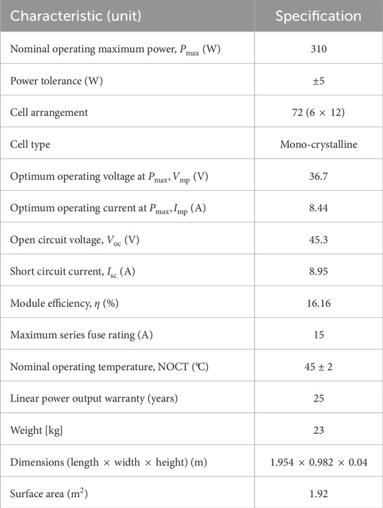
Table 1. The technical parameters of the “Canadian Solar” CS6X-310M (310W).
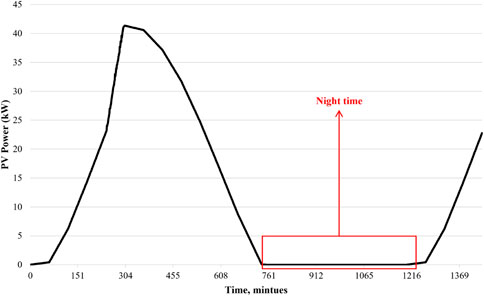
Figure 1. Total generation by PV from Astana to Almaty.
2.3 Wind energy system
The train’s speed is regarded in this study as the wind’s speed. As illustrated in Figure 2, it is evident that wind is caused by the train’s movement wherever it is. At an average speed of 50–60 km/h, the train creates air pressure in the opposite direction, according to Liu et al. (2024). When a train is in motion, the air is compressed, driving it to its sides and creating a vacuum at its sides and back (Bi et al., 2022).
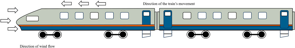
Figure 2. Model of the wind flow.
To fill this void, a tremendous volume of air flows into the train’s sides and rear. The wind speed is computed in this study based on the possibility that the train’s motion will produce wind. As previously stated, the Talgo train in Kazakhstan operates at a speed of around 110 km/h; hence, it may be said that the train’s motion creates a wind. Das et al. (2020) have presented a viable method where the wind is produced by the speed of the train. Table 2 demonstrates the technical characteristics of the selected WT. The output power generated by (Equation 4) and dataset is from the route of Astana to Almaty and varies the latitude and longitude based on train stops NASA Prediction Of Worldwide Energy Resources (POWER) (2025).
The output power of the WT, illustrated in Figure 3, is proportional to the wind speed. Here, the circular cross-sectional area is denoted by
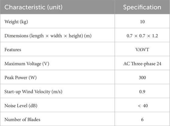
Table 2. Specifications of the vertical axis wind turbine (VAWT).
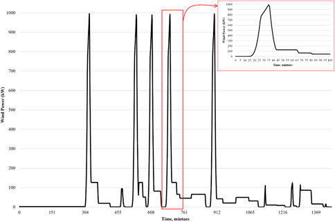
Figure 3. Total generation by WT from Astana to Almaty.
2.4 Solar sleeper
Railway sleepers with solar panels for energy supply, as shown in Figure 4. In Germany, the British energy business Bankset is now testing the idea of mounting solar panels over railroad rails. The technical specifications of the chosen solar sleeper are shown in Table 3. They showcased a bold proposal that intends to install gigawatts of PV systems on top of railway sleepers (Equation 5); (Ji et al., 2020). Based on dimensions in 1 km, we can install a 1,265 solar sleeper.
where
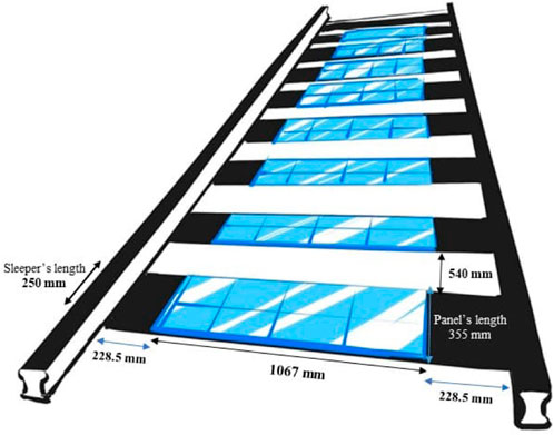
Figure 4. The solar panels are placed above the railway track’s sleepers.
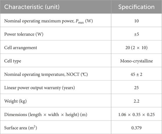
Table 3. Specifications of the small solar panel module.
2.5 Battery energy storage system (BESS)
A lead-acid BESS is used in this feasibility study to reduce the intermittent output power of RESs and the stochastic load profile of PHEVs. This parameter can be identified based on (Equation 6); Adefarati and Bansal (2019).
where
where
3 Methodology
This paper explores the use of RES on a moving electric train, study specifically in Almaty, Kazakhstan, reached by the “Talgo Tulpar” train from Astana. Building the system’s mathematical model is crucial since it aids in comprehending its constituent parts. This paper discusses the BESS and the solar sleepers along the intended route, in addition to the PV and WT on top of the train. Next, the right kind of wind turbine and solar panels have been chosen. The wind turbine is chosen as a tiny VAWT that is horizontally oriented, while the train and sleepers’ solar panels are both monocrystalline. Reducing the amount of energy coming from the upstream utility grid (primary energy network) is the aim of this endeavor, serve as the foundation for the mathematical model that is built. To meet the train’s energy needs, the share of RESs should be raised. The study identifies train characteristics, such as trip schedule and route length, to design an HES for rail transportation. The train’s technical parameters are crucial for determining roof space for PV and WT. In many industries, including transportation, an Energy Management System (EMS) is an essential technological framework that maximizes energy utilization, boosts operational effectiveness, and lessens environmental effects.
By reducing the import of fossil fuels, RES helps countries to increase energy security while maintaining their standard of life without harming nature. Together with other energy producers like fuel cells and microturbines, the microgrid (MG) uses RES like PV and WT. The idea was established to lower pollution levels and generate costs. The paper presents an HES for the railway, utilizing WT, PV, BESS, and solar sleepers as distributed resources. The EMS is based on a strategic plan to enhance the railway system’s energy network, as illustrated in Figure 5.
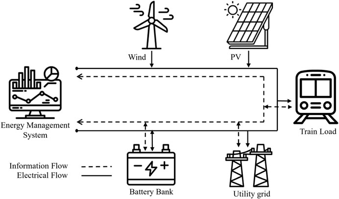
Figure 5. The hybrid energy systems constituent parts.
The BESS strategic plan aims to prioritize renewable energy generation over grid energy, as shown in Figure 6. If the State of Charge (SOC) is less than 85%, the plan calls for charging when the train’s need for renewable energy is exceeded. If there is enough SOC, excess energy is returned to the grid, optimizing power consumption and perhaps generating income through feed-in tariffs. While grid energy supports any additional load requirements, the BESS discharges to protect battery life and performance if the SOC is higher than 20%. This strategy shows a dedication to sustainable EMS and the ability of cutting-edge control systems to improve the use of RESs.
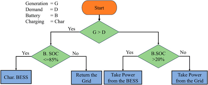
Figure 6. The BESS strategic plan to maximize grid energy use.
3.1 Study on train stops and dimensions
This paper examines the “Talgo Tulpar” train in Kazakhstan. Two of Kazakhstan’s major cities, Astana and Almaty, are connected via one of the “Talgo Tulpar” train’s most frequently traveled routes. In addition, the technical specification of the train and its parameters are illustrated in Table 4. As seen in Figure 7, the route is 1,200 km long and includes 11 stops, making the entire journey time 18 h and 49 min.
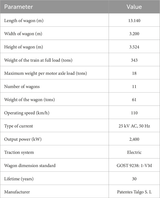
Table 4. Technical specifications of the train.
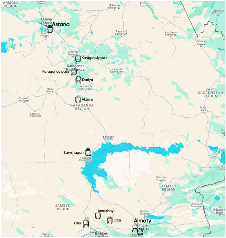
Figure 7. Train station map for Talgo Tulpar from Astana to Almaty.
Table 5 shows all the stations of the Talgo Tulpar train and also the arrival and departure times of the train. For the calculation of train load and generation of power using RESs, we consider the parking time of the train at one stop and also consider how much time it takes the train to move from one stop to another stop.
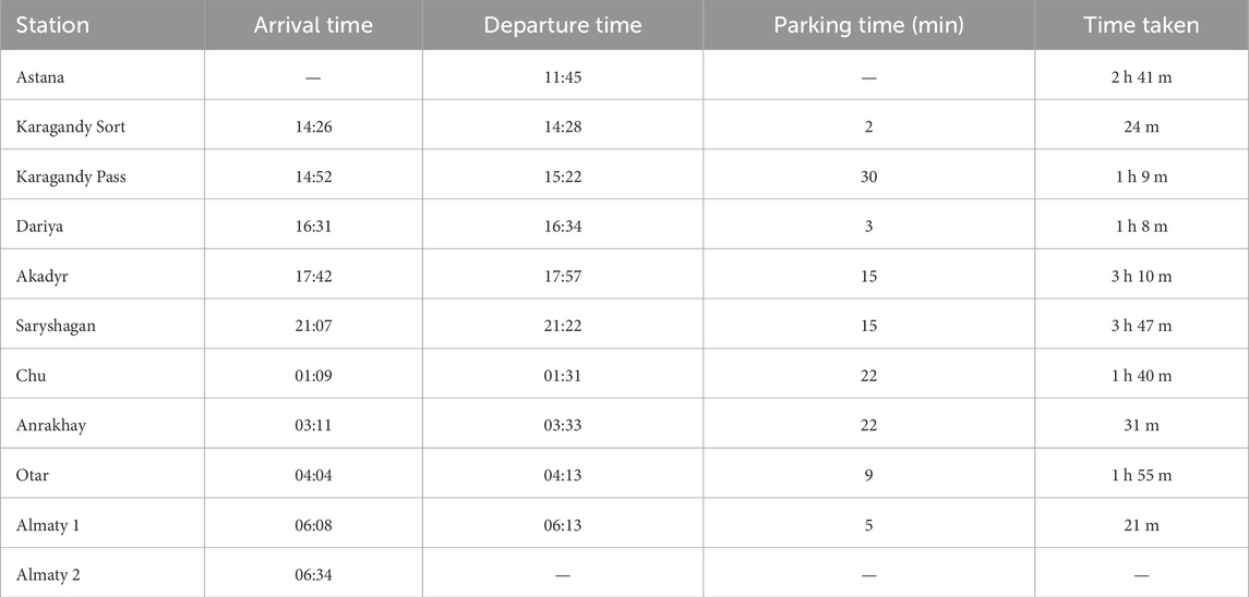
Table 5. Route details Astana to Almaty.
Figure 8 shows the side view of the train, and based on the dimensions, we make a calculation for how many PV and WT we can install. However, with a surface size of 1.954 * 0.982 m2, the chosen solar panel, “Canadian Solar” CS6X-310M, fully satisfies the wagon’s required width (0.982
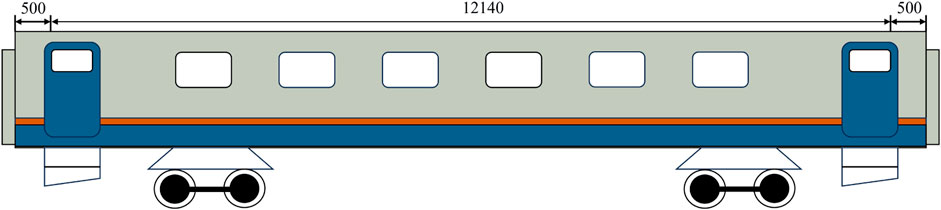
Figure 8. The wagon of the Talgo Tulpar train seen from the side (measurements in mm).
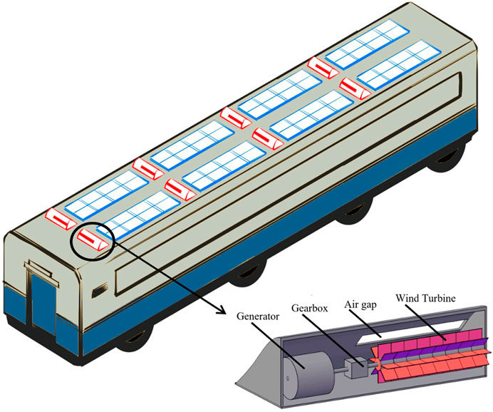
Figure 9. The placement of wind turbines and solar panels on a moving train conceptual design, taken and modified from (Nurmanova et al., 2017).
3.2 Train energy profile
The train energy consumption must be determined to simulate the HES. Since the train’s movement determines the majority of its energy usage, determining the train’s speed profile is important. The derived speed profile is used to assess the train’s energy usage. Consequently, the formulation is used to estimate the train’s energy consumption statistics. The power is found by multiplying the traction force by the train’s speed in (Equation 8).
where
Temperature, humidity, filth, and speed all have an impact on the adhesion coefficient, or
where,
As a result, real-time information on the chosen train’s speed or energy usage was needed. Since neither the speed nor the energy profile of this train is publicly available. As a result, the model that was supplied was used to build the velocity profile of the chosen train. Deng (2024) have taken into account the train’s speed fluctuation between stations while creating the speed profiles for the fast and slow modes. Figure 10 shows the power demand of a train traveling from Astana to Almaty.
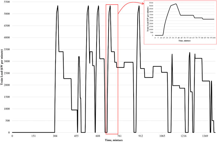
Figure 10. Talgo Tulpar train load profile, given kW per minute.
4 Case studies, results, and discussion
The integration of a HES into Kazakhstan’s railway network is presented in this study. The Talgo Tulpar train, a high-speed train built by Talgo S.L. of Spain, is undergoing a feasibility study to connect Almaty and Astana. The train is a well-traveled route between the two cities and is referred to as the “RENFE S130″ in Spain. With a 1200-km trip taking about 19 h, the train’s installation has greatly shortened travel times. At specific moments, stations might pause. The trip map is shown in Figure 8. Table 5 provides a thorough explanation of the Talgo train schedule between Astana and Almaty. Consequently, one complete day, or 24 h, was taken into consideration for the simulation studies (from 12:00 p.m. until 11:59 a.m. the next day). MATLAB algorithm simulation is used to simulate and evaluate the suggested system, which integrates RESs such as PV, WT, BESS, and the main grid. To investigate how the EMS reacts when sharing power across several sources in all operational modes, several situations are investigated. For a full day, we examined several scenarios for this simulation. There are three cases for this operation.
Case 1: PV and WT.
Case 2: PV, WT, and BESS.
Case 3: PV, WT, Solar Sleeper, and BESS.
In Case 1, the effectiveness of PV and micro-WT over a moving train is investigated, which is often referred to as the general or basic case. It is crucial to compare this basic case with different scenarios that take into account the integration of PV sleepers and storage systems. The graph depiction of the train’s load, RES usage, and grid energy consumption during motion is displayed in Figure 10. As is evident, the utility grid is primarily responsible for the train’s load. Figure 11 displays the PV and WT’s output power throughout the course of a complete day (12:00 p.m. to 11:59 a.m. the following day). The total generated energy from RESs and energy savings are obtained from the simulation.
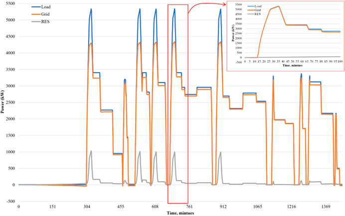
Figure 11. The train’s load, renewable energy use, and grid energy use graph.
In Case 2, the train energy system is equipped with PV, WT, and BESS systems. Examining how the BESS affects the train’s power system is the goal. This instance examines the BESS strategy plan in the HES depicted in Figure 6. The BESS’s SOC should remain between 20% and 85% to ensure battery longevity and reliability. If the SOC is outside the specified limits, a harsh penalty is applied. The particle swarm optimization (PSO) aims to keep the SOC within the permitted range to avoid penalties. Figure 12 shows the train’s load, RESs, and grid energy consumption during the journey. The PSO also aims to maximize the BESS’s charging and discharging conditions by adhering to the strategy plan.
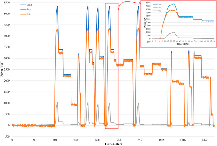
Figure 12. The train’s load, renewable energy use, and grid energy use graph.
Figures 13, 14 show the ideal BESS SOC level and BESS power depending on the SOC level. The BESS’s state of charging and discharging is visible. The charging state of the BESS is indicated by positive BESS power values, while the discharging state is shown by negative BESS power indications. When there is positive electricity, the battery’s stored energy increases because energy is entering the battery. Conversely, negative graph values show that energy is leaving the battery to satisfy the system’s power requirements.
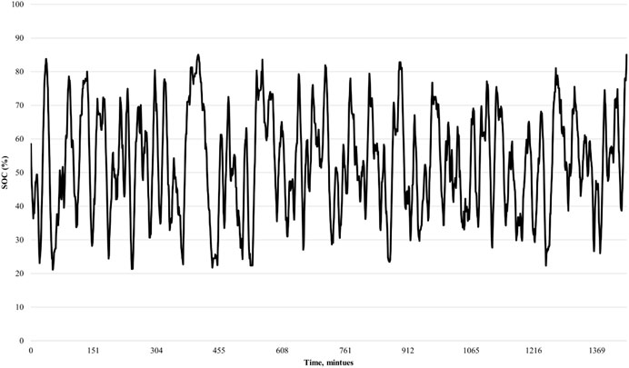
Figure 13. The optimized BESS SOC level.
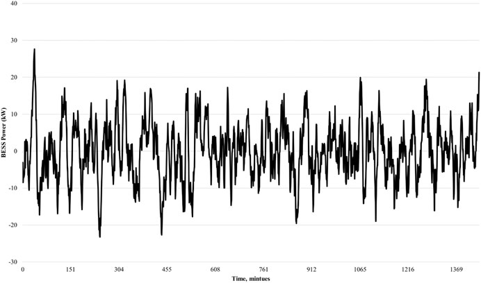
Figure 14. The optimized BESS Power.
However, the train’s energy requirements cannot be met by the quantity of RESs produced. Table 6 illustrates this by showing the figures for total grid power use, total renewable power generation, and the total BESS power storage. The grid’s energy usage is far higher than that of its renewable energy output. However, since the combined PV and WT are small-scale and situated above the train, it makes sense. There is an insignificant amount of renewable energy produced when the BESS is actively charging or discharging. This implies that certain system qualities, such as keeping a high SOC to handle unforeseen demand spikes or having a reserve for periods when renewables are not produced, are prioritized in the operational system design.
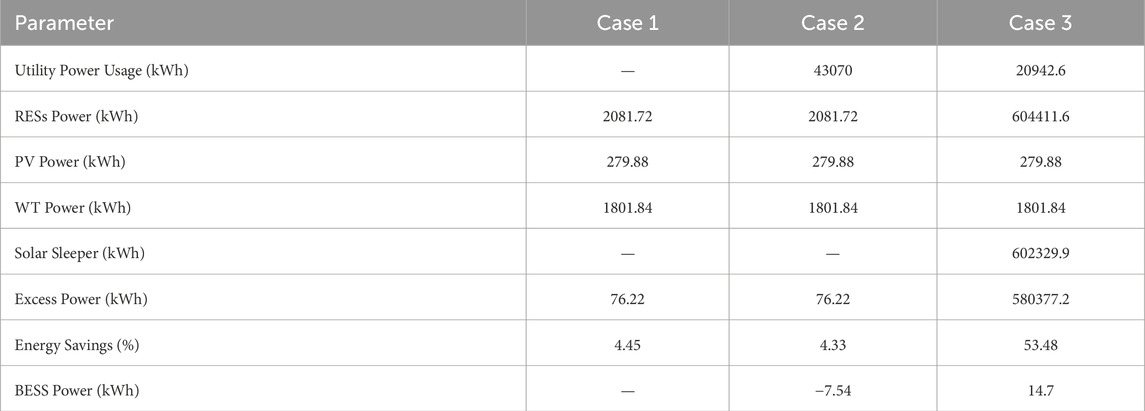
Table 6. Comparison of energy parameters in different cases.
A novel and untested technique of producing power across railway rails, Case 3 examines solar sleepers’ influence on the railway power system. These sleepers have a great potential for producing enormous amounts of energy, even if this has not been shown in the literature. The graph of the train’s load, RESs, and grid power consumption during the journey is shown in Figure 15. As is evident, a significant amount of energy is produced by all RESs, causing the excess energy to be sent back into the grid. The graph shows the high generation of hybrid power resources, with solar sleepers being the primary source of energy. However, the performance of these sleepers is influenced by the climate, which can affect their ability to meet the train’s energy demand.
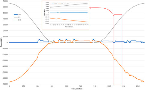
Figure 15. Grid energy use, train load, and renewable energy graph.
Furthermore, the suggested strategy has been implemented to optimize BESS charging and discharging decision options since case 3 also takes BESS into account. Based on the best charging and discharging choices, Figures 16, 17 display the optimal BESS SOC level and the BESS power indicators. With an SOC above 30%, the observation demonstrates that the BESS is actively charged and drained, preventing over-discharge. The BESS power has variability, frequently switching between charging and discharging, suggesting potential system optimization for stability. A balance among charging in excess and discharging at times of demand that is high or low generation is suggested by the distribution of positive and negative numbers.
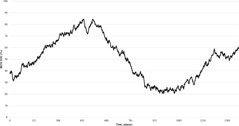
Figure 16. The optimized BESS SOC level.
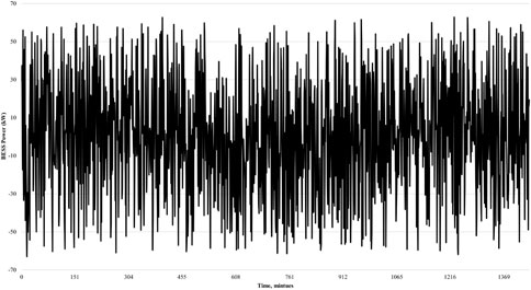
Figure 17. The optimized BESS Power.
Table 6 presents the features of the energy network using solar sleepers, as planned in the proposed strategic plan. Due to the substantial power generation capability of solar sleepers, the dependency on grid-supplied electricity can be significantly reduced. However, since solar sleepers do not operate continuously throughout the day, the train’s electrical load remains primarily reliant on grid power during periods of low solar efficiency.
This relates to around the hours of 6 p.m.–7 a.m. The indication of power savings in this research instance is substantially higher than in previous scenarios. Approximately 53.4% of the grid’s energy may be saved with the suggested configuration. Additionally, solar sleepers are used on the 1200-km railway track that connects Astana and Almaty. As a result, each element under consideration has a different energy generation index. Each resource’s energy generation index should be stabilized to reduce grid energy consumption.
5 Conclusion
This paper explores the incorporation of hybrid energy harvesting technologies into Kazakhstan’s rail network. The project is on a small-scale PV and WT energy application with a BESS on the Talgo Tulpar, a moving electric train. To evaluate the performance and energy-generating potential of the suggested HES, the research created a thorough mathematical model and employed MATLAB simulations. The study considered three case studies: PV/WT, PV/WT/BESS/Grid, and PV/WT/BESS/Grid/Solar sleepers. According to the findings, an effective EMS combined with PV and WT energy sources may greatly lessen reliance on the primary electricity grid. Even modest installations of PV and WT can result in energy savings. The addition of a BESS adds layer of efficiency, allowing for more efficient energy storage and usage. The study also investigated the high potential of solar sleepers, an innovative approach in the field.
Data availability statement
The original contributions presented in the study are included in the article/Supplementary Material, further inquiries can be directed to the corresponding author.
Author contributions
AK: Conceptualization, Data curation, Formal Analysis, Investigation, Methodology, Resources, Software, Validation, Visualization, Writing – original draft, Writing – review and editing, Funding acquisition, Project administration, Supervision. KA: Writing – original draft, Writing – review and editing, Conceptualization, Data curation, Formal Analysis, Funding acquisition, Investigation, Methodology, Project administration, Resources, Software, Supervision, Validation, Visualization. MB: Conceptualization, Data curation, Formal Analysis, Funding acquisition, Investigation, Methodology, Project administration, Resources, Software, Supervision, Validation, Visualization, Writing – original draft, Writing – review and editing.
Funding
The author(s) declare that financial support was received for the research and/or publication of this article. This work was supported in part by the Collaborative Research Project (CRP), Nazarbayev University under Grant 211123CRP1604, and in part by the Faculty Development Competitive Research Grant (FDCRG), Nazarbayev University under Grant 201223FD8811.
Conflict of interest
The authors declare that the research was conducted in the absence of any commercial or financial relationships that could be construed as a potential conflict of interest.
The author(s) declared that they were an editorial board member of Frontiers, at the time of submission. This had no impact on the peer review process and the final decision
Generative AI statement
The author(s) declare that no Generative AI was used in the creation of this manuscript.
Any alternative text (alt text) provided alongside figures in this article has been generated by Frontiers with the support of artificial intelligence and reasonable efforts have been made to ensure accuracy, including review by the authors wherever possible. If you identify any issues, please contact us.
Publisher’s note
All claims expressed in this article are solely those of the authors and do not necessarily represent those of their affiliated organizations, or those of the publisher, the editors and the reviewers. Any product that may be evaluated in this article, or claim that may be made by its manufacturer, is not guaranteed or endorsed by the publisher.
References
Adefarati, T., and Bansal, R. (2019). Reliability, economic and environmental analysis of a microgrid system in the presence of renewable energy resources. Appl. Energy 236, 1089–1114. doi:10.1016/j.apenergy.2018.12.050
Alshoufi, K., Al-Nagar, K., and Fischer, S. (2024). Integrating renewable energy into railway systems: a path to sustainable transportation – a review. Chem. Eng. Trans. 114, 817–822. doi:10.3303/CET24114137
Bakhtvar, M., and Al-Hinai, A. (2021). Robust operation of hybrid solar–wind power plant with battery energy storage system. Energies 14, 3781. doi:10.3390/en14133781
Bi, H., Wang, H., and Zhou, Y. (2022). Aerodynamic phenomena and drag of a maglev train running dynamically in a vacuum tube. Phys. Fluids 34, 096111. doi:10.1063/5.0104819
Das, S., Mazumder, D., Mia, N., and Rahman, S. (2020). “A review on power generation from wind power created by fast moving train perspective Bangladesh,” in 2020 IEEE international conference on technology, engineering, management for societal impact using marketing, entrepreneurship and talent (TEMSMET), 1–5. doi:10.1109/TEMSMET51618.2020.9557448
Deng, L., Cai, L., Zhang, G., and Tang, S. (2024). Energy consumption analysis of urban rail fast and slow train modes based on train running curve optimization. Energy Rep. 11, 412–422. doi:10.1016/j.egyr.2023.12.014
Fouladi, E., Baghaee, H. R., Bagheri, M., Lu, M., and Gharehpetian, G. B. (2020). “Bess sizing in an isolated microgrid including phevs and rers,” in 2020 IEEE international conference on environment and electrical engineering and 2020 IEEE industrial and commercial power systems Europe (EEEIC/ICPS Europe), 1–5. doi:10.1109/EEEIC/ICPSEurope49358.2020.9160640
Gerlici, J., Shavolkin, O., Kravchenko, O., Shvedchykova, I., and Haman, Y. (2025). Improvement of the hybrid renewable energy system for a sustainable power supply of transportation infrastructure objects. Future Transp. 5, 61. doi:10.3390/futuretransp5020061
Jayasudha, S., Krishnamoorthy, M., Saisandeep, M., Balasubramanian, K., Srinivasan, S., and Thaniaknti, S. B. (2021). Techno economic performance analysis of hybrid renewable electrification system for remote villages of India. Int. Trans. Electr. Energy Syst. 31, e12515. doi:10.1002/2050-7038.12515
Ji, L., Ning, F., Ma, J., and Jia, L. (2020). Swot analysis for orchestrated development of a solar railway system in China. IET Renew. Power Gener. 14, 3628–3635. doi:10.1049/iet-rpg.2020.0465
Jia, L., Ma, J., Cheng, P., and Liu, Y. (2020). A perspective on solar energy-powered road and rail transportation in China. CSEE J. Power Energy Syst. 6, 760–771. doi:10.17775/CSEEJPES.2020.02040
Khan, A., Bressel, M., Davigny, A., Abbes, D., and Ould Bouamama, B. (2025). Comprehensive review of hybrid energy systems: challenges, applications, and optimization strategies. Energies 18, 2612. doi:10.3390/en18102612
Kuznetsov, V., Hubskyi, P., Rojek, A., Udzik, M., and Lowczowski, K. (2024). Progress and challenges connected with the integration of renewable energy sources with railway distribution networks. Energies 17, 489. doi:10.3390/en17020489
Liu, D., Wang, C., Gonzalez-Libreros, J., Tu, Y., Elfgren, L., and Sas, G. (2024). Modified calculation model of train-induced aerodynamic pressure on vertical noise barriers considering the train geometry effect. J. Wind Eng. Industrial Aerodynamics 249, 105750. doi:10.1016/j.jweia.2024.105750
Madhusudanan, G., and Padhmanabhaiyappan, S. (2024). Solar power fluctuation smoothing through battery energy storage system using avoa-sagan approach. J. Energy Storage 101, 113610. doi:10.1016/j.est.2024.113610
Maleki, A., and Pourfayaz, F. (2015). Optimal sizing of autonomous hybrid photovoltaic/wind/battery power system with lpsp technology by using evolutionary algorithms. Sol. Energy 115, 471–483. doi:10.1016/j.solener.2015.03.004
Nurmanova, V., Bagheri, M., Sultanbek, A., Hekmati, A., and Bevrani, H. (2017). “Feasibility study on wind energy harvesting system implementation in moving trains,” in 2017 international Siberian conference on control and communications (SIBCON), 1–6. doi:10.1109/SIBCON.2017.7998495
Seifi Davari, H., Seify Davari, M., Botez, R., and Chowdhury, H. (2024). Advancements in vertical axis wind turbine technologies: a comprehensive review. Arabian J. Sci. Eng. 50, 2169–2216. doi:10.1007/s13369-024-09723-x
Stegenta, P., Daszkiewicz, P., and Far, M. (2024). Analysis of the use of photovoltaic panels on the roof and walls of passenger carriages to reduce electricity consumption. Rail Vehicles/Pojazdy Szyn., 18–27doi. doi:10.53502/RAIL-197328
Teng, J., Li, L., Jiang, Y., and Shi, R. (2022). A review of clean energy exploitation for railway transportation systems and its enlightenment to China. Sustainability 14, 10740. doi:10.3390/su141710740
Keywords: railway power system, renewable energy, energy management system, photovoltaic, wind turbine, solar sleeper
Citation: Khan AM, Akmurzina K and Bagheri M (2025) Feasibility study on hybrid energy harvesting solution in rail transportation system. Front. Energy Res. 13:1666388. doi: 10.3389/fenrg.2025.1666388
Received: 15 July 2025; Accepted: 14 October 2025;
Published: 03 November 2025.
Edited by:
Kashif Irshad, King Fahd University of Petroleum and Minerals, Saudi ArabiaReviewed by:
Chakrit Panpean, King Mongkut’s University of Technology North Bangkok, ThailandSamarendra Singh, Dr. Rammanohar Lohia Avadh University, India
Copyright © 2025 Khan, Akmurzina and Bagheri. This is an open-access article distributed under the terms of the Creative Commons Attribution License (CC BY). The use, distribution or reproduction in other forums is permitted, provided the original author(s) and the copyright owner(s) are credited and that the original publication in this journal is cited, in accordance with accepted academic practice. No use, distribution or reproduction is permitted which does not comply with these terms.
*Correspondence: Abdul Moeed Khan, YWJkdWxtb2VlZC5raGFuQG51LmVkdS5reg==