 Haoyu Zhu
 Xiaoran Wang2
 Nengling Tai
- 1College of Smart Energy, University of Shanghai Jiao Tong, Shanghai, China
- 2Schoool of Electronic Information and Electrical engineering, University of Shanghai Jiao Tong, Shanghai, China
When the energy storage power station encounters a fault on the transmission line during charging, active component of its short-circuit current still maintains an inverse relationship with the positive-sequence voltage at its grid connection point, influenced by the converter control strategy. This leads to a large phase difference between the short-circuit currents on both sides of the transmission line, posing a risk of no-trip failure in conventional current differential protection. To address the above issues, this paper proposes a differential protection scheme for transmission line connected to energy storage power stations based on positive-sequence reactive current, which can effectively avoid the influence of energy storage charging and discharging state on the differential current protection. The feasibility of the positive-sequence reactive current differential protection for transmission line connected to energy storage power station is analyzed through theoretical derivation. To address the issue of protection sensitivity being affected by line capacitive current when the fault voltage drop is relatively low, capacitive current compensation is added to the positive-sequence reactive current differential protection criterion. Finally, performance testing was conducted through PSCAD simulation. Results show that the proposed method can eliminate the impact of energy storage charge and discharge differences on the current differential protection performance and has good performance under different fault conditions.
1 Introduction
In recent years, electrochemical energy storage in various application forms has developed rapidly (Amin et al., 2023; Mohan et al., 2024; Tang, 2024). Among them, for grid-connected energy storage power stations, the Chinese national standards stipulate its dynamic reactive power support capability fault crossing, but do not stipulate the magnitude and direction of the active component of the short-circuit current at this time (National Standards of People’s Republic of China, 2023). Therefore, in current engineering practice, when energy storage power station encounters a fault on the transmission line during charging, its short-circuit current is characterized as injecting positive-sequence reactive current into the grid connection point and absorbing positive-sequence active current. Such short-circuit current characteristics will cause a large phase difference between the currents on both sides of the transmission line, resulting in a high risk of maloperation for conventional current differential protection (CDP).
Some studies have proposed protection improvement methods for the issue of the CDP no-trip failure caused by excessive phase difference. The improvement methods proposed in references (Guo et al., 2025; Lan et al., 2023; Zang et al., 2022) are based on the fault characteristics of photovoltaic and direct-drive wind turbines, and cannot adapt to the energy storage in charging state. Among them, reference (Guo et al., 2025) proposed a new principle of differential protection combining restraining current and restraining voltage, where the current restraining criterion can improve protection sensitivity compared to conventional criteria, the analysis in the paper was only conducted when the current phase difference was below 120°, which does not cover the range of current phase difference variations during energy storage charging. Reference (Lan et al., 2023) constructed a new differential protection principle by combining different phase currents on both sides of the line, but this method is based on the premise that the short-circuit current on the inverter-based power side is three-phase symmetrical. Reference (Zang et al., 2022) proposes a d-axis-based current differential protection scheme, but this scheme cannot adapt to the characteristics that energy storage absorb active current during charging.
The improvement methods proposed in references (Jia, 2022; Zhang et al., 2024; Liang et al., 2023; Zang et al., 2021; Mishra et al., 2022) can enhance the performance of current differential protection of the transmission line connected to energy storage power station under charging conditions, but there are still shortcomings. Among them, reference (Jia, 2022) proposes a current differential protection based on amplitude comparison, by utilizing the significant difference in short-circuit current amplitude between inverter-based power and the system. However, this method still faces the problem of insufficient sensitivity when the capacity of new energy station is large. Reference (Zhang et al., 2024) proposes an adaptive current differential improvement criterion that compensates for both current amplitude and phase for energy storage current differential protection. However, the constant coefficients in the amplitude compensation function and phase compensation function mentioned in the paper are not explained in terms of their meaning and selection principles, and there is no analysis or simulation on whether this criterion will cause protection maloperation during external faults. Reference (Liang et al., 2023) proposes an improved method for energy storage current differential protection. This method compensates both the magnitude and phase of the short-circuit current to improve protection sensitivity. However, selection principles of constant coefficients in the magnitude compensation function and phase compensation function mentioned in the paper are not explained, and there is no analysis or simulation on whether this criterion will cause protection maloperation during external faults. Reference (Zang et al., 2021) proposes an enhanced current differential protection that modifies the amplitude ratio and phase difference of currents on both sides of the line. This method can effectively improve the performance of current differential protection, but due to the need to ensure reliability during external faults, it still lacks sufficient sensitivity for internal faults when the current amplitude ratio is close to 1. Reference (Mishra et al., 2022) proposes a distribution network current differential protection scheme based on Q-axis current, but it does not consider the effect of line capacitive current, which may lead to insufficient sensitivity under conditions of high transition resistance. Moreover, the photovoltaic power capacity in its example is very small, which differs significantly from scenarios with large-capacity energy storage power stations accessing the grid. Reference (Farshad, 2021) uses the second harmonic components of Q-axis current and voltage to achieve protection of distribution networks containing photovoltaic power stations, but the paper does not address the protection performance when the inverter has harmonic suppression control strategies.
In addition, there are also some methods using indicators such as cosine similarity (Sirisha and Pradhan, 2020; Zheng et al., 2021; Zhang et al., 2019) and Pearson correlation coefficient to identify faults (Chen et al., 2018)- (Jia et al., 2018). These methods use a data-driven approach to avoid conventional protection performance issues caused by renewable energy sources, but outliers may have a significant impact on them.
In this paper, a positive-sequence reactive current differential protection suitable for transmission line connected to energy storage power station is proposed based on the fault characteristics of energy storage injecting.
Positive-sequence reactive current into the grid connection point during transmission line fault. This method first calculates the positive-sequence reactive current component on the local side using the positive-sequence voltage and positive-sequence current at the protection installation. Subsequently, based on the line capacitance parameters and bus voltage, the positive-sequence reactive current is compensated. The compensated positive-sequence reactive current component is used for longitudinal differential protection. This method can eliminate the phase difference caused by the absorption of active current during energy storage charging, avoiding the risk of no-trip failure.
2 Effect of energy storage charging on the CDP
2.1 Energy storage converter control strategy
For the current grid-connected energy storage, its converter control strategy usually adopts a dual closed-loop control method with a power outer loop and a current inner loop (Telukunta et al., 2017; Chen and Mei, 2015; National Standards of People’s Republic of China, 2021; National Standards of People’s Republi c of China, 2024). When different faults occur on the transmission line connected to energy storage power station, in order to meet the dynamic reactive power support capability specified by the current national standards and the current limiting requirements of the converter (National Standards of People’s Republic of China, 2023), the control targets for the positive sequence reactive and active components of the energy storage short-circuit current are shown in Equations 1, 2.
Where
2.2 Effect of active component of short-circuit current on the CDP
Influenced by the control strategy, no matter in the charging or discharging state, the direction of the positive-sequence reactive power component of the short-circuit current is always from the energy storage to the grid connection point when a short-circuit occurs in the transmission line connected to energy storage power station. However, the direction of its positive-sequence active current is directly related to the charging and discharging state of the energy storage.
Figure 1 shows the different relationship under charging and discharging conditions between short-circuit current of energy storage and voltage of the grid connection point.
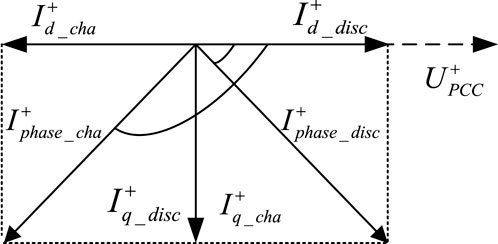
Figure 1. Characteristics of short-circuit current of energy storage.
From Figure 1, it can be seen that the phase difference between
3 Modified current differential protection based on adaptive phase compensation and its setting methods
According to the analysis in Section 2, it can be seen that no-trip failure of the CDP under the energy storage charging state is mainly caused by the active component of the short-circuit current provided by the energy storage power station. Therefore, this paper proposes a differential protection based on the positive-sequence reactive component of the short-circuit current to avoid the influence of the active component.
3.1 Energy storage converter control strategy
In the system shown in Figure 2, the feasibility of applying positive-sequence reactive current differential protection to the transmission line PQ is analyzed. The positive-sequence reactive currents at points P and Q are both calculated using the local voltage and current through d-q decomposition. Since only the positive-sequence reactive current is used, performance of the positive-sequence reactive current differential protection applied to the line PQ is basically unaffected by the difference between charging and discharging states. A feasibility analysis is conducted using the charging state as an example.
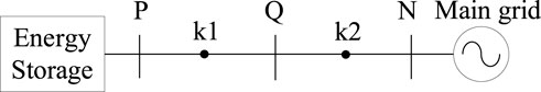
Figure 2. Characteristics of short-circuit current of energy storage.
3.1.1 Fault in the line PQ
When a fault occurs at a point k1 on the line PQ in Figure 2, the short-circuit current at bus Q is provided by the system side. At this time, the direction of the positive-sequence reactive current calculated from the positive-sequence voltage and positive-sequence current must be from bus Q to the fault point k1; bus P is the energy storage grid connection point. According to the fault ride-through standard, regardless of whether the energy storage is charging or discharging at this time, the direction of its positive-sequence reactive current is from bus P to the fault point k1.
3.1.2 Fault out of the line PQ
When the fault occurs at a point k2 on line QN in Figure 2, the direction of the positive sequence reactive current at bus P is still bus-pointing to the point of fault.
Assuming that the steady state of the control target can be reached after the fault, the voltage-current relationship at the energy storage grid connection point P can be written, resulting in Equation 3.
Where
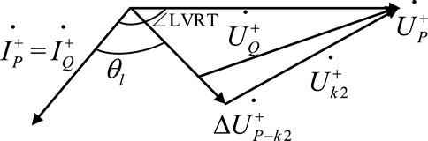
Figure 3. Phasor diagram of transmission line fault during energy storage charging.
In Figure 3, ∠LVRT is the angle between the positive-sequence voltage and positive-sequence current at the energy storage grid connection point, determined by the energy storage control strategy;
When the fault point is near point Q,
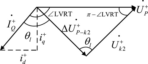
Figure 4. Phasor diagram of the critical condition.
From the geometric relationship shown in Figure 4, it can be obtained that when Equation 4 holds,
In(4),
When the fault type is a metallic three-phase short circuit, the positive sequence voltage at the energy storage grid connection point is too low to maintain a stable charging state.
If the fault type is other metallic short circuit,
In Equation 5,
3.2 Positive-sequence reactive current differential protection criterion
Based on the analysis results in Section A, the positive-sequence reactive current differential protection criterion (RCDP) can be designed as shown in Equation 6.
In(6),
In Equation 7, the coefficient 0.1 indicates the error of the current transformer;
3.3 Performance analysis of the RCDP
3.3.1 The effect of line capacitance
Feasibility of the RCDP has been analyzed in Section A in Chapter III based on short-circuit current characteristics of energy storage, but the effect of line distributed capacitance on protection performance under special fault conditions was not considered in the analysis process. In fact, as the transition resistance at the short-circuit point increases, the positive-sequence voltage at the energy storage grid connection point gradually rises to above 0.9 p. u. During this process, the positive-sequence reactive current provided by the energy storage power station gradually decreases to zero. For the system side, if the transition resistance continues to increase, the positive-sequence reactive component of its short-circuit current will also be reduced to the same order of magnitude as the line capacitance current, and thus the effect of line capacitance current on the RCDP is not negligible.
Since point P is the energy storage grid connection point, the reactive current at point P should be determined solely by the control strategy. The positive-sequence reactive current component at Q in Equation 8 should be the superposition of the positive-sequence reactive component of the line capacitive current and the reactive component of the short-circuit current when the line capacitive effect is neglected. The positive sequence component of the line capacitance current at Q is noted to be
In expression Equation 8, the left-side expression is the differential current, and the ratio of the differential current to the operating current
3.3.2 The effect of operating current setting methods
Operating current
3.4 Positive-sequence reactive current differential protection criterion considering line capacitance current compensation
Based on the above analysis, the positive-sequence reactive current differential protection considering line capacitive current compensation (CRCDP) is constructed as shown in Equation 9.
In (9),
Noting that the left side of Equation 9 is the differential amount, the right side is the restraining amount, and ratio of the restraining amount to the differential amount is protection sensitivity.
Protection action logic of the CRCDP is shown in Figure 5. The protection action signal needs to remain effective for more than 5 m to avoid maloperation caused by transient fluctuations.
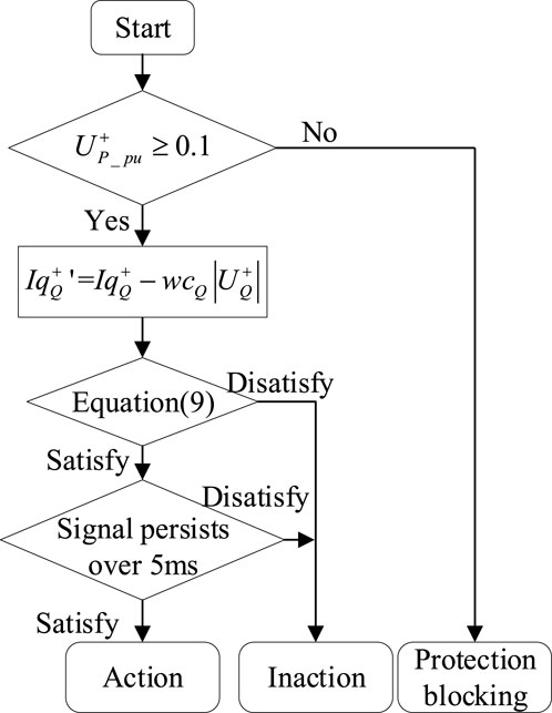
Figure 5. Protection action logic of the CRCDP.
4 Simulation verification
Build the simulation model according to the system structure shown in Figure 6. The equivalent impedance of the external system and line parameters are shown in Table 1. The lengths of lines PQ and QN are both 40 km, and the capacity of energy storage power station is 200 MW. The transformer has a voltage rating of 35kV/220 kV and a rated capacity of 300MVA. The control strategy and filter of the energy storage converter is shown in Figures 7a,b. In Figure 7b,
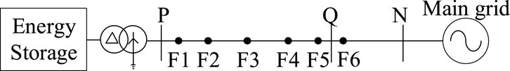
Figure 6. Structure of the grid-connected system of energy storage power station (a) Control strategy (b) Filter.
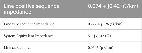
Table 1. Line parameters and system equivalent impedance.
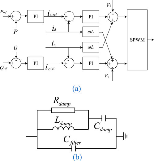
Figure 7. Control strategy and filter of the energy storage converter. (a) Control strategy. (b) Filter.
Points F1-F6 in Figure 6 are the fault locations to be used in the subsequent simulation, and the specific location descriptions of F1-F6 are shown in Table 2.
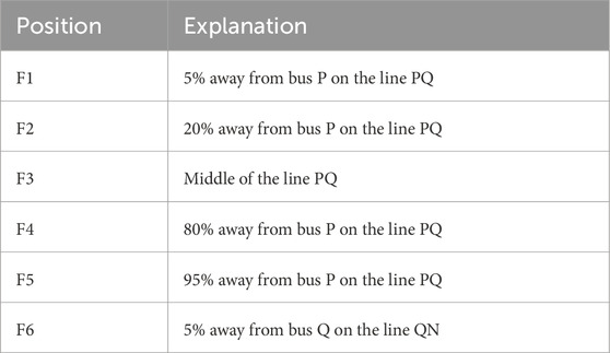
Table 2. F1-F6 position description.
Points F1-F6 in Figure 6 Table 2 are the fault locations to be used in the subsequent simulation, and the specific location descriptions of F1-F6 are shown in.
4.1 Tripping time comparison
In the simulation, the energy storage is set to operate in charging mode, and a fault occurs at the midpoint of the line PQ (F3 in Figure 6) at 1.5 s. The fault type is set as metallic phase A ground fault. Operating curves of CDP, RCDP, and CRCDP is shown in Figure 8.
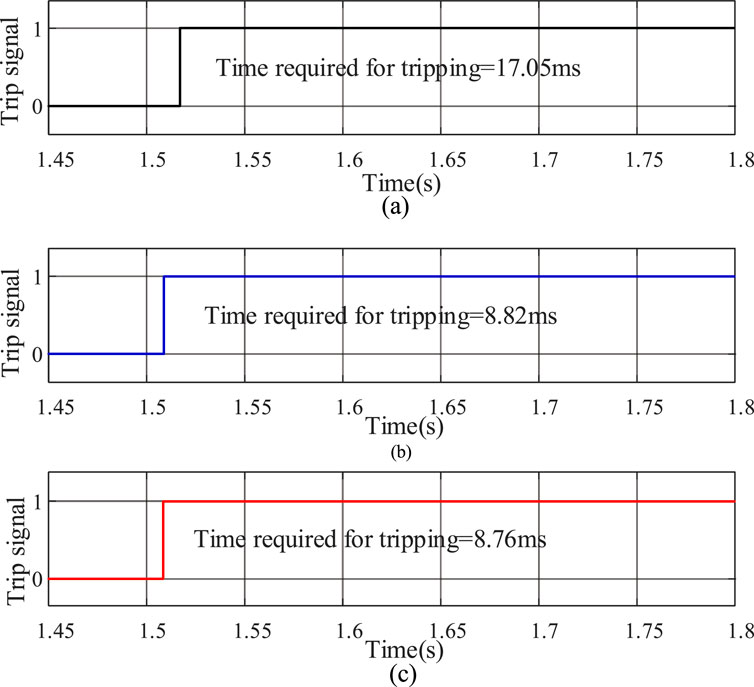
Figure 8. Operating curves of CDP, RCDP, and CRCDP. (a) Trip signal of CDP. (b) Trip signal of RCDP. (c) Trip signal of CRCDP.
As shown in Figure 8, the CDP, RCDP, and CRCDP can all correctly identify faults during metallic phase A ground fault. Among them, CDP requires the longest tripping time of 17.05 m. The tripping time of RCDP and CRCDP is significantly shorter than that of CDP, which is 8.82 m and 8.76 m, respectively.
4.2 Protection performance comparison during internal and external faults
4.2.1 Internal faults
In the simulation, the energy storage is set to operate in charging mode, and a fault occurs at the midpoint of the line PQ (F3 in Figure 6) at 1.5 s. The fault types and their corresponding transition resistances are shown in Table 3.
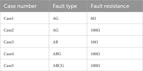
Table 3. Fault types and transition resistance.
The sensitivities of CDP, RCDP, and CRCDP corresponding to each fault are shown in Figures 9a–e. When the sensitivity exceeds 1 and remains above 5 m (as mentioned in Figure 5), the protection trips.
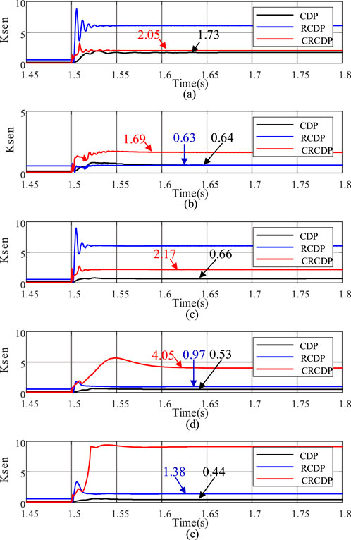
Figure 9. Protection performance of different types of internal faults. (a) AG0ohm. (b) AG100ohm. (c) AB10ohm. (d) ABG100ohm. (e) ABCG100ohm.
As shown in Figure 9, when the fault occurs during charging state, sensitivity of the CDP is seriously insufficient in faults from Case 2 to Case 5, posing a significant risk of protection no-trip failure. Sensitivity of the RCDP is very high in metallic phase A ground fault (Case 1) and AB phase-to-phase ground fault (Case 3), but when the transition resistance is high (Case 2 and Case 4), the sensitivity is only 0.63 and 0.97 respectively, also indicating insufficient sensitivity. Sensitivity of the CRCDP meets the operating conditions under various fault types.
4.2.2 External faults
In the simulation, the energy storage is set to operate in charging mode, and a fault occurs at 5% from bus Q on line QN (F6 in Figure 6) at 1.5 s. The fault types and their corresponding transition resistances are shown in Table 3. The sensitivities of CDP, RCDP, and CRCDP corresponding to each fault are shown in Figures 10a–e.
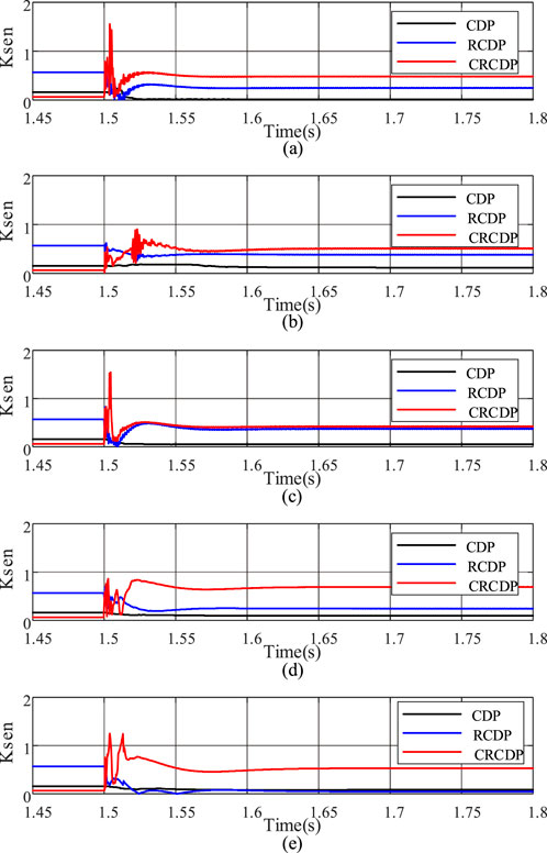
Figure 10. Protection performance of different types of external faults. (a) AG0ohm. (b) AG100ohm. (c) AB10ohm. (d) ABG100ohm. (e) ABCG100ohm.
As shown in Figure 10, when external faults occur, sensitivity of the CRCDP may only exceed 1 during the transient process after the fault, but the duration does not exceed 5 m, which does not meet the signal duration requirement for protection trip. Thus, no maloperation occurs. The CRCDP has sufficient reliability for external faults.
4.3 Effect of transition resistance on protection performance
In the simulation, the energy storage is set to operate in charging mode. A three-phase short circuit occurs at the midpoint of the line PQ (F3 in Figure 6) at 1.5 s. The transition resistances are 10Ω, 50Ω, 100Ω, and 200Ω respectively. The sensitivities of CDP, RCDP, and CRCDP corresponding to each fault are shown in Figures 11a–e.
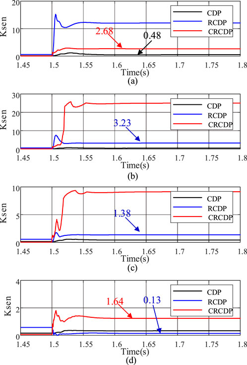
Figure 11. Comparison of protection sensitivity at different transition resistances. (a) Fault resistance: 10ohm. (b) Fault resistance: 50ohm. (c) Fault resistance: 100ohm. (d) Fault resistance: 300ohm
As can be seen from Figure 10, the sensitivity of the CDP is seriously insufficient, even when the transition resistance is low (10Ω), its sensitivity is only 0.48, which can not meet the action requirements, and there is a greater risk of protection no-trip failure; the RCDP has a high sensitivity when the transition resistance is low, but its ability to resist the transition resistance is poor. When the transition resistance reaches 300Ω, its sensitivity is only 0.13, there is also a greater risk of protection no-trip failure; CRCDP maintains high sensitivity throughout the changes in transition resistance. Even when the transition resistance increases to 300Ω, its sensitivity reaches 1.64, ensuring accurate protection operation.
4.4 Effect of fault location on protection performance
In the simulation, the energy storage is set to operate in the charging state, and a phase A grounded short circuit occurs at positions F1-F5 in Figure 6 at 1.5 s, with a transition resistance of 100Ω. The sensitivity and operation status of CRCDP corresponding to faults at F1-F5 are shown in Table 4.
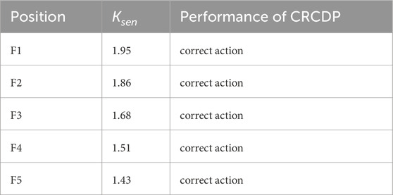
Table 4. Sensitivity and protection action status of the CRCDP for faults F1 through F5.
As can be seen from Table 4, as the fault point moves from point F1 to point F5, the sensitivity of CRCDP gradually decreases, but it can always ensure normal protection operation.
4.5 Effect of energy storage capacity on protection performance
In the simulation, the energy storage capacities are set to 100 MW, 150 MW, 200 MW, and 250 MW respectively, with the energy storage operating in charging mode. At 1.5 s, phase A grounded short circuit occurs at the midpoint of the line PQ (P3 in Figure 6), with a transition resistance of 100Ω. The CRCDP sensitivity corresponding to each energy storage capacity is shown in Figure 12.
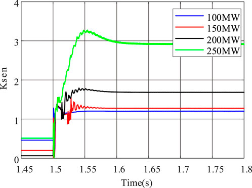
Figure 12. CRCDP sensitivity at different energy storage capacities.
As shown in Figure 12, the energy storage capacity has a significant impact on the sensitivity of CRCDP. The larger the energy storage capacity, the higher the sensitivity. When the energy storage capacity is 100 MW, the sensitivity of CRCDP is relatively low at about 1.21, which can still ensure normal protection operation.
4.6 Effect of charging and discharging states on protection performance
Take phase A grounded short circuit as an example, the sensitivity and action status of CRCDP under different charging and discharging states are explained. The transition resistance is set to 100Ω, and the fault start time is 1.5 s. The fault locations are set to P3 and P6 in Figure 6, respectively. For each fault location, the energy storage is set to be in charging and discharging states, respectively. The specific fault conditions are shown in Table 5.
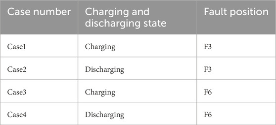
Table 5. Fault location and storage charge/discharge status.
The CRCDP sensitivity and action status corresponding to case 1- case 4 in Table 5 are shown in Table 6.
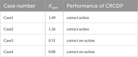
Table 6. CRCDP sensitivity and action status corresponding to case 1- case 4.
As can be seen from Table 6, CRCDP can correctly identify faults under both charging and discharging conditions. Under the same fault conditions, the sensitivity of CRCDP in the energy storage charging state is higher than that in the discharging state because the voltage on line PN during energy storage charging is lower than that during discharging, resulting in a larger positive sequence reactive current. The positive-sequence voltage amplitude of bus P corresponding to Case 1 and Case 2 is shown in Figure 13.
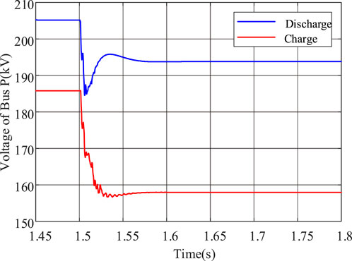
Figure 13. Positive-sequence voltage magnitude of bus P corresponding to case1 and case2.
5 Conclusion
The positive-sequence reactive current differential protection proposed in this paper can effectively reduce the risk of current differential protection no-trip failure caused by excessive phase difference of short-circuit current on both sides of the transmission line when the energy storage power station is charging, and has the following conclusions:
1. The method proposed in this paper only uses the positive-sequence reactive component and can adapt to during both charging and discharging states of the energy storage power station. In addition, since the reactive current support capability provided by PV, direct-drive wind turbines, etc. is similar to that of grid-connected energy storage under the current standards, the protection proposed in this paper can also be applied to the transmission lines of photovoltaic power stations and direct-drive wind farms.
2. The method has sufficient sensitivity under different transition resistances, fault locations and fault types, and performs better when the capacity of the energy storage plant is larger, which can adapt to the development trend of gradual growth of the energy storage power station capacity.
Data availability statement
The original contributions presented in the study are included in the article/supplementary material, further inquiries can be directed to the corresponding authors.
Author contributions
HZ: Conceptualization, Data curation, Formal Analysis, Methodology, Validation, Visualization, Writing – original draft. XW: Investigation, Validation, Writing – original draft. CF: Project administration, Supervision, Writing – review and editing. YH: Supervision, Writing – review and editing. NT: Supervision, Writing – review and editing.
Funding
The author(s) declare that financial support was received for the research and/or publication of this article. This work was supported by Shanghai Outstanding Academic Leaders Program (No.22XD1401400) and National Natural Science Foundation of China (No. 52337006).
Conflict of interest
The authors declare that the research was conducted in the absence of any commercial or financial relationships that could be construed as a potential conflict of interest.
Generative AI statement
The author(s) declare that no Generative AI was used in the creation of this manuscript.
Any alternative text (alt text) provided alongside figures in this article has been generated by Frontiers with the support of artificial intelligence and reasonable efforts have been made to ensure accuracy, including review by the authors wherever possible. If you identify any issues, please contact us.
Publisher’s note
All claims expressed in this article are solely those of the authors and do not necessarily represent those of their affiliated organizations, or those of the publisher, the editors and the reviewers. Any product that may be evaluated in this article, or claim that may be made by its manufacturer, is not guaranteed or endorsed by the publisher.
References
Amin, M. A., Suleman, A., Waseem, M., Iqbal, T., Aziz, S., Faiz, M. T., et al. (2023). Renewable energy maximization for pelagic islands network of microgrids through battery swapping using deep reinforcement learning. IEEE Access 11, 86196–86213. doi:10.1109/access.2023.3302895
Chen, L. J., and Mei, S. W. (2015). An integrated control and protection system for photovoltaic microgrids. CSEE J. Power Energy Syst. 1 (1), 36–42. doi:10.17775/cseejpes.2015.00005
Chen, L., Lin, X., Li, Z., Wei, F., Zhao, H., Bo, Z., et al. (2018). Similarity comparison based high-speed pilot protection for transmission line. IEEE Trans. Power Deliv. 33 (2), 938–948. doi:10.1109/tpwrd.2017.2731994
Farshad, M. (2021). A pilot protection scheme for transmission lines of half-bridge MMC-HVDC grids using cosine distance criterion. IEEE Trans. Power Deliv. 36 (2), 1089–1096. doi:10.1109/tpwrd.2020.3001878
Guo, Y., Zhou, Z., and Li, Y. (2025). New principle of line differential protection based on combined current and voltage restraint principle. Proc. CSEE 1-14. doi:10.13334/j.0258-8013.pcsee.232465
Jia, K., Gu, C. J., Xuan, Z. W., Li, L., and Lin, Y. Q. (2018). Fault characteristics analysis and line protection design within a large-scale photovoltaic power plant. IEEE Trans. Smart Grid 9 (5), 4099–4108. doi:10.1109/tsg.2017.2648879
Jia, K., Yang, Z., Fang, Y., Zhu, Z., Zheng, L., Bi, T., et al. (2022). Pilot protection based on amplitude comparison for renewable power teed lines. CSEE J. Power Energy Syst. 8 (6), 1519–1529.
Lan, C., Huang, S., Zhang, J., Meng, J., Zhang, H., and Zheng, X. (2023). “A novel principle of current differential protection for renewable energy station,” in 2023 IEEE International Conference on Advanced Power System Automation and Protection (APAP). Xuchang, China, 08-12 October 2023, IEEE, 519–523.
Liang, Y., Ren, Y., and He, W. (2023). An enhanced current differential protection for AC transmission lines connecting MMC-HVDC stations. IEEE Syst. J. 17 (1), 892–903. doi:10.1109/jsyst.2022.3155881
Mishra, P., Singh, P., Pradhan, A. K., and Bajpai, P. (2022). Protecting distribution systems with inverter-interfaced PV plants using Q-Axis components. IEEE Syst. J. 16 (2), 1763–1773. doi:10.1109/jsyst.2021.3071627
Mohan, M., Yan, J., Chi, Y., Asim Amin, M., and Liu, Y. (2024). A market-based real-time algorithm for congestion alleviation incorporating EV demand response in active distribution networks. Appl. Energy 356, 122426. doi:10.1016/j.apenergy.2023.122426
National Standards of People's Republic of China (2024). Technical requirements for connecting photovoltaic power station to power system, standardization administration of the People's Republic of China GB/T, 19964.
National Standards of People's Republic of China (2021). Technical specification for connecting wind farm to power system—Part 1: on shore wind power, 19963. Beijing: Standardization Administration of the People's Republic of China.
National Standards of People's Republic of China. (2023). Technical requirements for power conversion system of electrochemical energy storage system, standardization administration of the People's Republic of China GB/T 34120-2023.
Sirisha, A. N. R. L., and Pradhan, A. K. (2020). Cosine similarity based directional comparison scheme for subcycle transmission line protection. IEEE Trans. Power Deliv. 35 (5), 2159–2167. doi:10.1109/tpwrd.2019.2962275
Tang, X. (2024). Research progress and prospect of energy storage planning method for new power system. Automation Electr. Power Syst. 48 (9), 178–191.
Telukunta, V., Pradhan, J., Agrawal, A., Singh, M., and Srivani, S. G. (2017). Protection challenges under bulk penetration of renewable energy resources in power systems: a review. CSEE J. Power Energy Syst. 3 (4), 365–379. doi:10.17775/cseejpes.2017.00030
Zang, L., Zou, G., Zhou, C., Sun, L., and Du, X. (2021). “A current differential protection scheme based on Q-axis component for distribution networks,” in 2021 6th Asia Conference on Power and Electrical Engineering. Chongqing, China, 08-11 April 2021, IEEE, 24–28.
Zang, L., Zou, G., Zhou, C., Zheng, M., and Du, T. (2022). Ad-axis based current differential protection scheme for an active distribution network. Prot. Control Mod. Power Syst. 7 (2), 23–11. doi:10.1186/s41601-022-00243-0
Zhang, Y., Li, Y., Song, J., Chen, X., Lu, Y., and Wang, W. (2019). “Pearson correlation coefficient of current derivatives based pilot protection scheme for long-distance LCC-HVDC transmission lines,” in 2019 IEEE 8th International Conference on Advanced Power System Automation and Protection (APAP). Xi'an, China, 21-24 October 2019, IEEE, 1367–1371.
Zhang, Y., Yu, Y., Yang, G., Zheng, T., and Sun, T. (2024). “Adaptive current differential protection principle for transmission line connected to energy storage power station based on amplitude and phase compensation,” in 2024 3rd International Conference on Energy and Electrical Power Systems (ICEEPS). Guangzhou, China, 14-16 July 2024, IEEE, 49–53.
Keywords: energy storage, differential current protection, reactive current, charging and discharging state, transmission line
Citation: Zhu H, Wang X, Fan C, Hu Y and Tai N (2025) Positive sequence reactive current differential protection of transmission lines connected to energy storage power station. Front. Energy Res. 13:1666514. doi: 10.3389/fenrg.2025.1666514
Received: 15 July 2025; Accepted: 23 September 2025;
Published: 30 October 2025.
Edited by:
Muhammad Waseem, Maynooth University, IrelandCopyright © 2025 Zhu, Wang, Fan, Hu and Tai. This is an open-access article distributed under the terms of the Creative Commons Attribution License (CC BY). The use, distribution or reproduction in other forums is permitted, provided the original author(s) and the copyright owner(s) are credited and that the original publication in this journal is cited, in accordance with accepted academic practice. No use, distribution or reproduction is permitted which does not comply with these terms.
*Correspondence: Haoyu Zhu, emh5MTE5MDMxOTEwMDI2QHNqdHUuZWR1LmNu; Chunju Fan, ZmFuY2h1bmp1QHNqdHUuZWR1LmNu; Yan Hu, eWFuaHVAc2p0dS5lZHUuY24=