 Haiyang Liang
 A. Minfu2
- 1Inner Mongolia Wuhai Ultra High Voltage Power Supply Bureau, Wuhai, China
- 2Inner Mongolia Electric Power Research Institute, Hohhot, China
The increasing penetration of distributed generation and the evolving requirements of smart grids have heightened the demand for fast, accurate, and robust reactive power control in Static Synchronous Compensators (STATCOMs). While proportional-integral (PI) controllers remain widely adopted, their reliance on iterative tuning and limited performance under low switching frequencies restricts their application in modern high-voltage cascaded H-bridge (CHB) systems. This paper proposes a novel discrete-time deadbeat current control method formulated directly in the synchronous rotating dq reference frame. By transforming AC currents into DC signals, the control structure is simplified and enables precise decoupled regulation of active and reactive currents. Unlike conventional approaches that discretize analog-domain designs, the proposed controller is derived analytically in the discrete domain, eliminating the need for parameter tuning or empirical adjustment. Simulation studies confirm that the approach achieves excellent current tracking accuracy, robust performance under ±10% inductance and −10% to +40% resistance variations, and maintains low total harmonic distortion even at low switching frequencies. These features make the method particularly suitable for high-voltage cascaded H-bridge STATCOM applications. Furthermore, stability analysis demonstrates that the closed-loop poles remain inside the unit circle across parameter deviations, ensuring reliable operation. The results indicate that the proposed approach provides a practical, fully digital control solution that improves accuracy, robustness, and implementation efficiency in modern smart grid environments.
1 Introduction
As a critical device in Flexible AC Transmission Systems (FACTS), the Static Synchronous Compensator (STATCOM) has been extensively and deeply applied in modern power systems due to its superior performance (Zhong, 2020). With the rapid development of renewable energies, power generation fluctuation issues have become increasingly prominent. STATCOMs, with their fast and accurate reactive power regulation capabilities, play a pivotal role in maintaining grid stability (Pereira et al., 2011). They significantly enhance voltage quality and system stability, providing reliable support for efficient grid integration of clean energy (Kroposki et al., 2010). The response speed of STATCOM to changes in reactive power demand is crucial, typically requiring regulation within a single fundamental cycle to ensure stable operation. The performance of the current regulator directly affects reactive current output, making it a core component in reactive power compensation.
In practical applications, STATCOMs are controlled using digital controllers. The conventional PI control strategy involves designing the controller in the continuous domain, followed by discretization for digital implementation. Due to the inevitable time delays in digital processing, a one-step delay in control output is usually adopted to avoid constraints on PWM duty cycles (Shan et al., 2009). However, this delay introduces phase lag, which reduces the phase margin of the closed-loop system and negatively affects stability (Yang, 2015). Furthermore, selecting an appropriate PI controller bandwidth and mitigating the influence of the delay are major challenges in achieving both fast response and high steady-state accuracy.
Deadbeat control is a control strategy specifically designed for discrete-time systems and can be effectively implemented in digital controllers. It offers the fastest possible response (minimum steps) with zero steady-state error (Kawamura et al., 1988). In the discrete domain, the one-step delay can be incorporated into the plant model, whereas in the continuous domain it requires complex approximations like Padé approximation (Ellis, 2004). Although some deadbeat control methods for STATCOM exist, most are designed in stationary reference frames (Camargo et al., 2020; Chen et al., 2015). In these frameworks, the current reference signal is sinusoidal, making it difficult to eliminate steady-state error despite achieving fast tracking. This is because existing methods primarily focus on pole placement for fast response, neglecting the characteristics of the input signal (Luo et al., 2015). Recent advances in predictive and repetitive controllers offer alternatives, but they typically involve high computational effort and iterative prediction, which hinder their practical deployment in high-power STATCOM systems.
To address these limitations, this paper proposes a deadbeat current control method for STATCOM based on the dq rotating reference frame. The main contributions are as follows:
• By transforming AC quantities to DC quantities using synchronous rotating coordinates and designing the controller in the discrete domain, the method achieves fast response and zero steady-state error. It also offers strong tracking and parameter adaptation capabilities, providing an effective solution for STATCOM current control.
• Unlike conventional PI control, this method avoids frequency characteristic distortion during the discretization process and maintains more stable control performance under low-frequency conditions.
• Differing from existing deadbeat methods based on stationary coordinates, this approach uses step signals in the dq frame as references, enabling truly zero steady-state error control.
The proposed method offers a novel and effective approach to STATCOM current control, characterized by fast dynamics, high steady-state accuracy, and strong parameter adaptability—enhancing the control performance of STATCOMs and supporting power system stability.
The paper is organized as follows: Section 2 analyzes the STATCOM model in dq reference frame; Section 3 presents the control sequence and algorithm design of the deadbeat controller; Section 4 validates the method’s performance through simulation and robustness analysis; and Section 5 concludes the paper with major findings and outcomes.
2 System model of STATCOM in dq reference frame
This study focuses on a star-connected Cascaded H-Bridge (CHB) STATCOM circuit topology, as shown in Figure 1. The device consists of three identical phase circuits, with each phase connected to a 35 kV power grid through a filter inductor L. The same number of H-bridge modules are cascaded in each phase, using Carrier Phase-Shifted Pulse Width Modulation (CPS-PWM) for switching control. This reduces the voltage stress on individual devices and ensures high-quality output voltage waveforms.
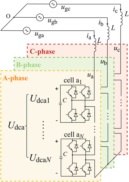
Figure 1. Star-connected CHB STATCOM main circuit.
Each H-bridge module contains an independent floating capacitor C.
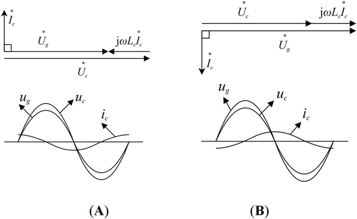
Figure 2. Phasor Diagram of STATCOM Operation, where (A) indicate the capacitive operating condition and (B) indicate the inductive operating condition.
Ideally, there is no active power exchange between STATCOM and the grid. The output voltage vector
Let the grid voltage magnitude be
According to the circuit relationships in Figure 1, and considering the filter inductor current as the state variable, including the inductor equivalent resistance R, the voltage balance equation is shown in Equation 2:
Applying the synchronous rotating dq transformation yields the time-domain model of the STATCOM plant in the dq frame:
Where
Where
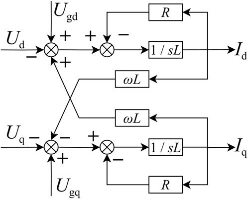
Figure 3. Block diagram of STATCOM plant in the dq reference frame.
According to instantaneous power theory (Akagi et al., 2017a; Akagi et al., 2017b), the instantaneous active and reactive powers drawn from the grid are shown in Equation 5:
With the d-axis aligned with the grid voltage vector, q-axis voltage component
The control of active and reactive currents
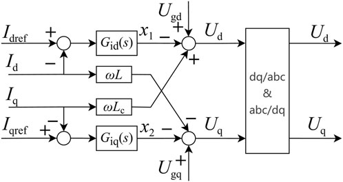
Figure 4. Controller structure of STATCOM in the dq reference frame.
By treating the coordinate transformation processes as unity gain elements and canceling the coupling paths between the controller and the plant, Figures 3, 4 can be combined and simplified into the equivalent control system structure shown in Figure 5, which represents active and reactive current control in the dq reference frame. The control structures for both active and reactive currents are identical, and the plant is modeled as a first-order low-pass system composed of the filter inductance and its equivalent resistance.
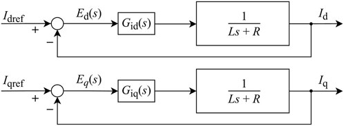
Figure 5. Equivalent control structure for active and reactive current loops.
As shown in Figure 5, the simplified control structure reveals that both active and reactive current controllers operate over identical low-pass plant models, facilitating a unified control design strategy.
Conventional designs of
3 Design of deadbeat current controller for STATCOM
The modulation technique employed in this paper for the multilevel cascaded STATCOM modules is the unipolar double-frequency Carrier Phase-Shifted Pulse Width Modulation (CPS-PWM) method (Shan et al., 2009). Within a single H-bridge module, the two arms share identical triangular carrier signals, while their reference signals are inverted. Across the cascaded H-bridge units, the triangular carriers are uniformly distributed over a 180° phase shift. Harmonic analysis of the unipolar double-frequency converter indicates that the equivalent output switching frequency using CPS-PWM reaches 2N times the carrier frequency (Akagi et al., 2017b; Wu, 2006), where N is the number of cascaded H-bridge modules. Under low switching frequency operation, the combination of module cascading and unipolar CPS-PWM not only increases the effective switching frequency—thus reducing switching losses—but also significantly improves the output voltage waveform quality by lowering total harmonic distortion (THD) (Basnet and Roinila, 2024b). This topology and modulation scheme is particularly well suited for high-power applications.
In the digital control system implementation, each H-bridge module updates its PWM reference signal at both the peak and valley points of the triangular carrier waveform. As a result, each phase effectively updates the reference signal 2N times within one carrier period, aligning the control frequency with the system’s equivalent switching frequency. Considering inherent delays in the digital control process—such as sampling, data holding, and computational latency—a one-step delayed update scheme is adopted for the PWM reference output. Accordingly, the control sampling period is set to one 2N-th of the carrier cycle. Depicted in Figure 6 is the control timing for a phase of N series-connected modules in the STATCOM, where N = 3. Owing to calculation delays, the voltage reference update is invariably delayed by one sampling period, Ts. Control timing sequence for one phase of the STATCOM with three cascaded H-bridge modules, illustrating the sampling instant, computation delay, zero-order hold, and PWM update process. The diagram clarifies how the discrete-time controller synchronizes with the carrier-based CPS-PWM strategy.
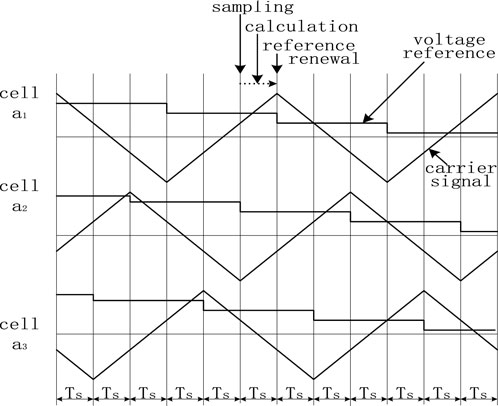
Figure 6. The control timing for a phase of three series-connected modules in the STATCOM.
The discrete-time digital control block diagram of the STATCOM current loop is shown in Figure 7, where
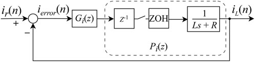
Figure 7. Discrete-time digital control block diagram of the current loop.
The transfer function of ZOH in the s-domain is shown in Equation 6:
The ZOH, combined with the filter inductance L and resistance R, constitutes a continuous-time low-pass subsystem. After discretization, and together with the one-sample delay element
The open-loop current path consists of the current regulator
If the desired Z-domain closed-loop transfer function is specified, the controller expression
The requirement of deadbeat control is that the closed-loop system reaches a steady state with zero error in the minimum number of sampling periods for a given input, which inherently imposes constraints on the system’s Z-domain transfer function.
Based on Equation 8, the Z-domain transfer function of the current loop error can be derived as follows:
In Figure 7, the reference input of the current control loop
Combining with Equation 10, the Z-transform of the current error sequence
According to the final value theorem for discrete-time systems, the steady-state value of the current error sequence is calculated in Equation 13:
To ensure zero steady-state error, the transfer function
According to the realizability requirements of deadbeat control (Ellis, 2004), the delay element in the system’s open-loop path must not be canceled by the controller; otherwise, the system becomes non-causal. Hence, the delay component must appear in the closed-loop transfer function. Specifically, the closed-loop transfer function
Subject to the following constraint:
Solving Equations 14, 15, yields:
From the expression of
Furthermore, based on Equations 7, 9, the Z-domain expression
Equation 17 defines the final form of the deadbeat current regulator, whose structure inherently includes predictive and derivative characteristics, providing superior transient response. Discretizing a PID transfer function via the Tustin method yields the following z-domain form:
Where kp, ki, and kd represent the proportional, integral, and derivative gains of the PID controller, respectively. Equations 17, 18, are mathematically equivalent in structure, but differ in the method of obtaining coefficients. Since its mathematical structure is similar to that of PID, the implementation of a deadbeat controller is very straightforward. Like PI controllers, PID controller parameters typically require selection based on empirical bandwidth estimation and iterative tuning (Shen, 2021).
From another perspective, the deadbeat controller proposed in this paper can be regarded as a PID controller whose parameters are derived analytically rather than through heuristic tuning (Mattavelli, 2005). Due to the inclusion of a derivative term, the controller theoretically provides faster dynamic response than a PI controller (Elhassan et al., 2022). Moreover, the design process does not rely on analog-domain knowledge or experience, offering a fully digital approach to controller design.
4 Simulation and stability analysis
To verify the proposed method, a simulation model of the CHB-STATCOM was built in Matlab Simulink. Key parameters are shown in Table 1:
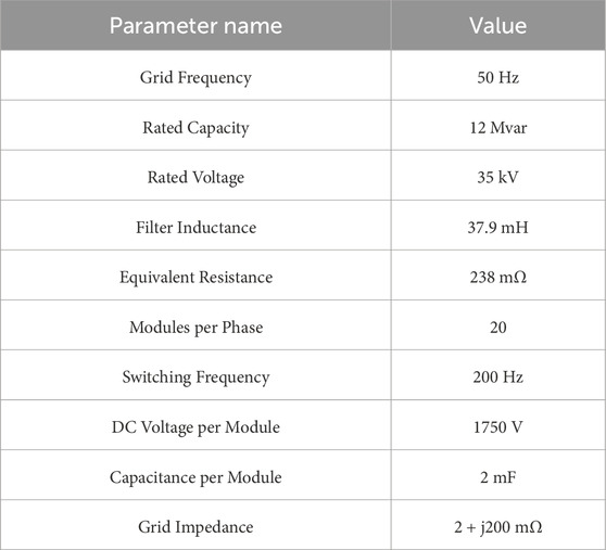
Table 1. Parameters of the STATCOM simulation model.
Based on the model parameters, the equivalent switching frequency of the digital controller is calculated as 2 × 20 × 200 = 8 kHz, corresponding to a sampling control period of 125 μs. According to Equation 17, the resulting controller transfer function is:
Figure 8 shows the simulation waveforms. The initial reactive power reference is set to −10 Mvar, and at 0.6 s, it switches to +10 Mvar. A positive reference corresponds to inductive reactive power, while a negative reference indicates capacitive operation.

Figure 8. (A) STATCOM phase-A output voltage. (B) Grid phase-A voltage. (C) STATCOM phase-A current. (D) Reactive power output of STATCOM. Simulation waveforms for reactive power transition from −10 Mvar to +10 Mvar.
Figure 8A illustrates the multilevel output voltage waveform of phase A from the STATCOM, and Figure 8B shows the corresponding grid voltage waveform of phase A. The STATCOM output voltage remains in phase with the grid voltage throughout the process. In inductive operation, the STATCOM output voltage is lower than the grid voltage; in capacitive operation, the output voltage exceeds that of the grid. This behavior is consistent with the operating principle illustrated in Figure 2.
Compared to the inductive case, the capacitive operation raises the grid voltage level. Figure 7C presents the injected phase A current from the STATCOM. During the dynamic transition from inductive to capacitive operation, the current phase undergoes a 180-degree shift. Figure 7D shows the actual reactive power output of the STATCOM. The reactive power transition is completed within 20 m, with no overshoot, demonstrating the controller’s ability to respond quickly to step changes in the reactive power command.
Figure 9 illustrates the multilevel output voltage waveform of STATCOM phase A. Theoretically, with 20 cascaded H-bridge modules, a maximum of 41 voltage levels can be achieved. In practice, the number of output levels depends on the magnitude of the output voltage—higher voltage results in more voltage steps. Figure 9a corresponds to a −10 Mvar inductive operating condition, while Figures 9b–d correspond to −5 Mvar (inductive), +5 Mvar (capacitive), and +10 Mvar (capacitive) operating conditions, respectively. As the reactive power increases, the output voltage magnitude increases accordingly (Lin et al., 2025), along with a greater number of voltage levels. Under a PWM carrier frequency of 200 Hz, the proposed dq-based deadbeat current control method enables the generation of highly sinusoidal multilevel output waveforms (Basnet and Roinila, 2024b).
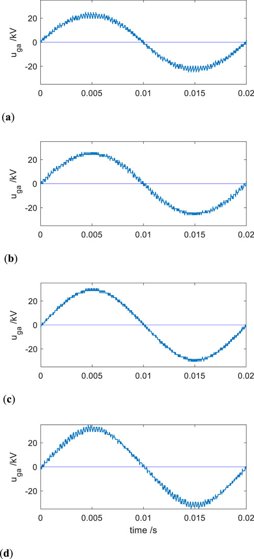
Figure 9. (a) STATCOM phase-A voltage at −10 Mvar (inductive load). (b) STATCOM phase-A voltage at −5 Mvar (inductive load). (c) STATCOM phase-A voltage at +5 Mvar (capacitive load). (d) STATCOM phase-A voltage at +10 Mvar (capacitive load). Output voltage waveforms of STATCOM under different operating conditions.
Table 2 compares the total harmonic distortion (THD) of output current between the proposed deadbeat control method and a conventional proportional-integral (PI) controller. The comparison clearly shows that the deadbeat method provides superior current waveform quality. This is consistent with earlier analytical results: although the deadbeat digital controller is functionally similar to a continuous-time Proportional-Integral-Derivative (PID) controller, its parameter design method is fundamentally different. The deadbeat controller parameters are directly calculated from Equation 17, eliminating the need for iterative tuning.
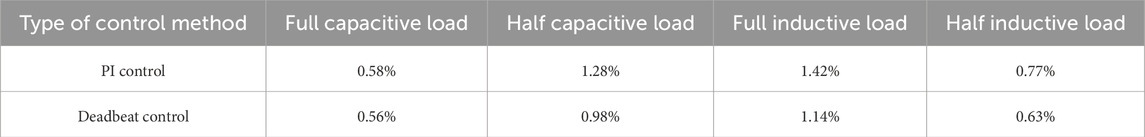
Table 2. Comparison of output current THD: PI control vs deadbeat control.
In contrast, conventional PI controllers lack a derivative component and must rely on increasing the proportional gain to improve response speed. However, excessive gain can lead to instability. Implementing a classical PID controller would require a more complex tuning process, often involving multiple iterations, making it difficult to achieve optimal performance in a single design cycle.
The THD values for all tested load conditions are consistently lower under deadbeat control, verifying the method’s capability to maintain waveform quality even during load transitions. The deadbeat control method exhibits excellent fast-response characteristics. However, in a closed-loop control system, speed and stability are often inherently contradictory objectives. During simulation analysis, the inductance and resistance parameters are assumed to be fixed. In practical scenarios, however, deviations in component values are inevitable. 1t is assumed that the STATCOM’s filter inductance may vary by ±10% from its nominal value, and the equivalent resistance may vary within the range of −10% to +40%. The parameter tolerance ranges of ±10% for inductance and −10% to +40% for resistance are chosen to reflect typical manufacturing deviations and operating temperature variations encountered in utility-scale STATCOM hardware.
Based on these tolerance ranges for L and R, the boundary conditions of the plant parameters are defined, and the pole distribution of the closed-loop system under deadbeat current control is plotted, as shown in Figure 10.
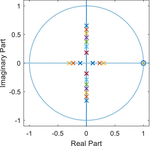
Figure 10. Distribution diagram of closed-loop poles under parameter variations.
As observed from Figure 10, the closed-loop system contains a pair of complex conjugate poles and one real pole, all located within the unit circle, indicating that the system remains stable. The real pole lies close to a real-axis zero, forming a pole-zero pair that essentially cancels out and thus has a negligible influence on the dynamics of the current loop. Consequently, the complex conjugate poles become the dominant factor affecting system performance. Although the poles shift outward under parameter variations, the root locus remains within the unit circle, indicating system stability and robustness to component tolerances (Li et al., 2020).
As actual parameters deviate from their nominal design values, the complex conjugate poles gradually move outward from the origin along the left side of the imaginary axis. Simulation results confirm that satisfactory current waveform quality is maintained across the full range of parameter variations.
5 Discussion
The simulation results presented in this study demonstrate that the proposed dq-based deadbeat current control method achieves rapid dynamic response and zero steady-state error under various operating conditions. Compared with conventional PI controllers, which often require iterative tuning and are sensitive to parameter variations, the deadbeat controller exhibits consistent performance across a wide range of system configurations and component tolerances. This robustness is particularly valuable in high-voltage multilevel STATCOM systems, where parameter mismatches and switching frequency constraints are common.
The success of the deadbeat strategy stems from two core features: the direct design in the discrete-time domain and the transformation of sinusoidal current references into DC quantities via the dq coordinate system. These features simplify the control problem, allowing for exact, closed-form computation of control voltage inputs. Unlike existing deadbeat methods applied in stationary reference frames—which are limited by their inability to fully eliminate steady-state error—the proposed dq-domain approach enables accurate and stable tracking without sacrificing control responsiveness.
From a systems integration perspective, the method also supports low switching frequencies, which is advantageous for reducing switching losses and improving the efficiency of cascaded H-bridge (CHB) STATCOMs. The observed total harmonic distortion (THD) results confirm that the proposed method generates high-quality current waveforms, even under dynamic reactive power transitions. This aligns with findings in recent studies that advocate for control strategies tailored directly in the digital domain (Carrasco et al., 2006) to overcome discretization-induced limitations in classical controllers. During practical implementation, the sampling interval must meet the requirements for computational real-time performance. Additionally, signal filtering is also a critical aspect. The bandwidth of the current filter should be set as close as possible to half of the sampling frequency in order to achieve the desired rapid control response.
However, certain practical challenges remain. The controller assumes ideal capacitor voltage balance across all H-bridge modules, which may not hold in real-world implementations. Unequal DC capacitance or charge accumulation can introduce voltage imbalance that may interfere with the current control loop. Further research is needed to investigate how local voltage balancing strategies interact with the global current regulation scheme (Cheng et al., 2024; Jin et al., 2018). Additionally, parameter optimization for more complex grid disturbances (Arya and Singh, 2013), non-ideal measurement feedback, and communication delays represent important directions for future work. Exploring adaptive or learning-based extensions of the deadbeat framework could also enhance its applicability in evolving power grid environments (Yang et al., 2024).
6 Conclusion
This paper presents a discrete-time deadbeat current control method for STATCOM systems based on the dq reference frame. By designing the controller directly in the digital domain and using coordinate transformation to simplify current regulation, the proposed approach achieves fast, accurate, and robust performance without requiring iterative parameter tuning. Simulation results validate its effectiveness under diverse operating conditions, confirming its potential as a practical and high-performance solution for modern STATCOM applications.
Data availability statement
The raw data supporting the conclusions of this article will be made available by the authors, without undue reservation.
Author contributions
HL: Conceptualization, Methodology, Project administration, Writing – original draft. AM: Conceptualization, Methodology, Writing – original draft. YaZ: Conceptualization, Writing – review and editing. YiZ: Writing – review and editing, Formal Analysis. SZ: Writing – original draft, Writing – review and editing. YuZ: Writing – review and editing, Project administration. YwZ: Writing – review and editing, Resources. ZT: Funding acquisition, Writing – review and editing.
Funding
The author(s) declare that financial support was received for the research and/or publication of this article. This research was funded by the Science and Technology project of Inner Mongolia Power (Group) Co., Ltd. (2024-4-40). The funder was not involved in the study design, collection, analysis, interpretation of data, the writing of this article, or the decision to submit it for publication.
Conflict of interest
Authors HL, YaZ, YiZ, SZ, YuZ, YwZ, and ZT were employed by Inner Mongolia Wuhai Ultra High Voltage Power Supply Bureau. Author AM was employed by Inner Mongolia Electric Power Research Institute.
Generative AI statement
The author(s) declare that no Generative AI was used in the creation of this manuscript.
Any alternative text (alt text) provided alongside figures in this article has been generated by Frontiers with the support of artificial intelligence and reasonable efforts have been made to ensure accuracy, including review by the authors wherever possible. If you identify any issues, please contact us.
Publisher’s note
All claims expressed in this article are solely those of the authors and do not necessarily represent those of their affiliated organizations, or those of the publisher, the editors and the reviewers. Any product that may be evaluated in this article, or claim that may be made by its manufacturer, is not guaranteed or endorsed by the publisher.
References
Akagi, H., Inoue, S., and Yoshii, T. (2007). Control and performance of a transformerless Cascade PWM STATCOM with star configuration. IEEE Trans. Ind. Appl. 43 (4), 1041–1049. doi:10.1109/TIA.2007.900487
Akagi, H., Watanabe, E. H., and Aredes, M. (2017a). Instantaneous power theory and applications to power conditioning. 2nd ed. Hoboken, NJ, USA: John Wiley and Sons, Inc.
Akagi, H., Watanabe, E. H., and Aredes, M. (2017b). “The instantaneous power theory,” in Proceedings of the instantaneous power theory and applications to power conditioning.
Arya, S. R., and Singh, B. (2013). Performance of DSTATCOM using leaky LMS control algorithm. IEEE J. Emerg. Sel. Top. Power Electron. 1 (2), 104–113. doi:10.1109/JESTPE.2013.2266372
Basnet, H., and Roinila, T. (2024a). “Decoupled deadbeat current controller for STATCOM application,” in Proceedings of the 2024 international conference on smart energy systems and technologies (SEST).
Basnet, H., and Roinila, T. (2024b). Combining proportional-integral, deadbeat, and repetitive current controllers in energy-storage-equipped STATCOM application. IEEE Access 12, 99499–99507. doi:10.1109/ACCESS.2024.3419444
Camargo, R. S., Mayor, D. S., Miguel, A. M., Bueno, E. J., and Encarnação, L. F. (2020). A novel cascaded multilevel converter topology based on three-phase Cells—CHB-SDC. Energies 13, 4789. doi:10.3390/en13184789
Carrasco, J. M., Franquelo, L., Bialasiewicz, J., Galvan, E., PortilloGuisado, R., Prats, M., et al. (2006). Power-electronic systems for the grid integration of renewable energy sources: a survey. IEEE Trans. Ind. Electron. 53 (4), 1002–1016. doi:10.1109/TIE.2006.878356
Chen, H., Sun, B., Qu, J., and Fu, K. (2015). “An improved deadbeat control strategy for D-STATCOM based on frequency-adaptive repetitive predictor,” in Proceedings of the 2015 IEEE international conference on cyber technology in automation, control, and intelligent systems (CYBER).
Cheng, Y., Zhang, H., Xing, J., and Xiao, Z. (2024). An improved two-beat deadbeat synchronous predictive current control strategy for MMC based on newton interpolation method. Front. Energy Res. 12, 1385029. doi:10.3389/fenrg.2024.1385029
Elhassan, G., Zulkifli, S. A., Iliya, S. Z., Bevrani, H., Kabir, M., Jackson, R., et al. (2022). Deadbeat current control in grid-connected inverters: a comprehensive discussion. IEEE Access 10, 3990–4014. doi:10.1109/ACCESS.2021.3138789
Ellis, G. (2004). Control system design guide: using your computer to understand and diagnose feedback controllers. Amsterdam, Netherlands: Elsevier.
Franklin, G. F., Powell, J. D., and Woekma, M. (2006). Digital control of dynamic systems. 3rd ed. Half Moon Bay, California: Ellis-Kagle Press.
Jin, Y., Wang, J., Xie, B., Li, L., and Ji, Y. (2018). A diode-clamped cascaded H-bridge STATCOM for voltage balancing of individual capacitors. Electr. Power Syst. Res. 163, 452–460. doi:10.1016/j.epsr.2018.07.010
Kawamura, A., Chuarayapratip, R., and Haneyoshi, T. (1988). Deadbeat control of PWM inverter with modified pulse patterns for uninterruptible power supply. IEEE Trans. Ind. Electron. 35 (2), 295–300. doi:10.1109/41.192662
Kroposki, B., Pink, C., DeBlasio, R., Thomas, H., Simões, M., and Sen, P. K. (2010). Benefits of power electronic interfaces for distributed energy systems. IEEE Trans. Energy Convers. 25 (3), 901–908. doi:10.1109/TEC.2010.2053975
Li, C., Burgos, R., Wen, B., Tang, Y., and Boroyevich, D. (2020). Analysis of STATCOM small-signal impedance in the synchronous d-q frame. IEEE J. Emerg. Sel. Top. Power Electron. 8 (2), 1894–1910. doi:10.1109/JESTPE.2019.2942332
Lin, Z., Zhang, X., Zhu, J., Du, W., Ye, J., and Bai, Y. (2025). Advances in space vector modulation techniques for multilevel inverters: a comprehensive review. Chin. J. Electr. Eng. 11 (2), 63–77. doi:10.23919/CJEE.2025.000146
Luo, A., Xiao, H., and Shuai, Z. (2015). Double deadbeat-loop control method for distribution static compensator. IET Power Electron 8, 1104–1110. doi:10.1049/iet-pel.2014.0435
Mattavelli, P. (2005). An improved deadbeat control for UPS using disturbance observers. IEEE Trans. Ind. Electron. 52 (1), 206–212. doi:10.1109/TIE.2004.837912
Pereira, M., Retzmann, D., Lottes, J., Wiesinger, M., and Wong, G. (2011). “SVC PLUS: an MMC STATCOM for network and grid access applications,” in Proceedings of the 2011 IEEE trondheim PowerTech (Trondheim, Norway), 19–23.
Shan, H., Peng, L., Kong, X., Ouyang, H., Liu, Z., and Wang, S. (2009). Effect of digital process on the performance of pulse width modulation inverter. Proc. CSEE 29, 29–35. doi:10.3321/j.issn:0258-8013.2009.06.005
Shen, Q. (2021). Research on control strategy and improvement of reactive power compensation capability for CHB STATCOM under unbalanced grid. Nanjing, China: Nanjing University of Aeronautics and Astronautics.
Yang, K. (2015). Research on key technology of cascaded distribution static synchronous compensator. Hangzhou, China: Zhejiang University.
Yang, X., Zhang, Y., Liu, Y., and Jiang, S. (2024). Model assisted extended state observer-based deadbeat predictive current control for modular multilevel converter. Electronics 13 (19), 3789. doi:10.3390/electronics13193789
Keywords: static synchronous compensator, deadbeat control, cascaded H-bridge, discrete-time control, dq reference frame, reactive power compensation, total harmonic distortion
Citation: Liang H, Minfu A, Zhang Y, Zhang Y, Zhan S, Zhang Y, Zhang Y and Tian Z (2025) Discrete-time deadbeat control for STATCOMs based on dq reference frame: a high-speed, tuning-free strategy for reactive current regulation. Front. Energy Res. 13:1667565. doi: 10.3389/fenrg.2025.1667565
Received: 16 July 2025; Accepted: 19 September 2025;
Published: 10 October 2025.
Edited by:
Zhiwei Li, North China Electric Power University, ChinaReviewed by:
Chenxi Wu, Hangzhou Dianzi University, ChinaBo Zhang, North China Electric Power University (Baoding), China
Copyright © 2025 Liang, Minfu, Zhang, Zhang, Zhan, Zhang, Zhang and Tian. This is an open-access article distributed under the terms of the Creative Commons Attribution License (CC BY). The use, distribution or reproduction in other forums is permitted, provided the original author(s) and the copyright owner(s) are credited and that the original publication in this journal is cited, in accordance with accepted academic practice. No use, distribution or reproduction is permitted which does not comply with these terms.
*Correspondence: Haiyang Liang, MTUxNDczMjUxMjNAMTYzLmNvbQ==