 Coby H. Scrudder1Lopamudra Das2Jin Ho Kang3Vesselin I. Yamakov2Ji Su3
 Donald A. Dornbusch4Rocco P. Viggiano4
 Yi Lin3*
- 1NASA Office of STEM Engagement (OSTEM) Internship Program, NASA Langley Research Center, Hampton, VA, United States
- 2Analytical Mechanics Associates, Hampton, VA, United States
- 3Advanced Materials and Processing Branch, NASA Langley Research Center, Hampton, VA, United States
- 4Materials Chemistry and Physics Branch, NASA Glenn Research Center, Cleveland, OH, United States
Solid-state batteries (SSBs) are poised to become the batteries of the future with advantages such as higher energy density, versatile geometry, and greater safety due to their inherent nonflammability. The most important parameter of the solid-state electrolyte (SSE) used is its ionic conductivity typically calculated from measuring the bulk impedance of a SSE pellet sandwiched between two ion-blocking current collectors. One of the challenges in conducting this measurement is the poor interfacial contacts between the SSE pellet and the current collector surfaces. To overcome this interfacial issue, high stack pressure (>10–100 MPa) is often used. However, this is unrealistic for the operation of practical cells where low or minimal stack pressure (<5 MPa) is more desirable. Thus, ionic conductivity values obtained at high stack pressures may not accurately reflect the true conducting properties under operational conditions. Holey graphene (hG) is a carbon nanomaterial with high electrical conductivity and unique dry compressibility, which is unusual for carbon materials. In this work, it is demonstrated that a thin layer of dry-pressed holey graphene as the current collector for sulfide-based SSE impedance measurements significantly improves the interfacial contact. The ionic conductivity values obtained at low stack pressure conditions were sometimes an order of magnitude higher than the data measured for sulfide SSEs without the hG layers. The use of hG also allows for convenient measurements even using coin cells where a very low internal stack pressure is used. The measurements attained in this work confirm that sulfide SSE ionic conductivity could be at a high level despite the low stack pressure used. This work also calls for more standardized measurement procedures to reduce the discrepancies in reported ionic conductivity values.
1 Introduction
The use of lithium-ion batteries (LIBs) has grown significantly in the past 2 decades, encompassing everything from consumer electronics to electric vehicles, due to their high-energy density and low costs (Armand and Tarascon, 2008; Evarts, 2015; Liu et al., 2019). However, LIBs have many disadvantages stemming from their flammability, small operating temperature window, and narrow electrochemical stability window. All-solid-state batteries (ASSBs, SSBs), typically utilizing an inorganic, polycrystalline solid-state electrolyte (SSE) in place of the liquid, organic electrolytes used in traditional LIBs, are inherently non-flammable and may enable a safer and more energy dense storage solution (Famprikis et al., 2019; Lee et al., 2021; Wang et al., 2021; Wu et al., 2021; Yu et al., 2021; Janek and Zeier, 2023; Kalnaus et al., 2023).
Many current SSEs fall behind the ionic conductivity of commercial organic liquid electrolytes (OLEs), and as such, ionic conductivity of SSEs is a key metric for enabling practical SSBs (Xie et al., 2024). Traditional OLEs such as LiPF6 in carbonate-based solvents have a room temperature ionic conductivity of 5–10 mS/cm, while many sulfide-based SSEs are close to this value (Lee et al., 2021; Wang et al., 2021; Wu et al., 2021; Yu et al., 2021). Despite the key importance of this metric, there is little standardization around how to test the ionic conductivity of SSEs. Testing is usually done with vastly different amounts of stack pressure applied in different research labs, leading to measured ionic conductivity sometimes varying by an order of magnitude for the same material (Lee et al., 2021; Wang et al., 2021; Wu et al., 2021; Yu et al., 2021).
Most current SSB research applies high stack pressure with custom-built split cells (or Swagelok cells), a more common choice for SSE ionic conductivity measurements and SSB cycling (Doux et al., 2020; Xiao et al., 2020; Cronau et al., 2021; Yang and Wu, 2022; Faka et al., 2023; Xie et al., 2024). However, it has been recognized that practical SSBs should use much lower stack pressure not exceeding 10 MPa, or even lower to be comparable to LIBs with OLEs (Famprikis et al., 2019; Lee et al., 2021; Wang et al., 2021; Wu et al., 2021; Yu et al., 2021; Janek and Zeier, 2023; Kalnaus et al., 2023). Typical OLE batteries use coin cells or pouch cells, where minimal stack pressure is applied. Recently emerged all-solid-state thin film batteries may also function under minimal to no stack pressure (Deng et al., 2023; Ke et al., 2024; Ke and Wang, 2025). Therefore, it is highly desirable that the SSB testing also takes the common coin or pouch cell formats toward practical applications.
A key issue with measuring the ionic conductivity of SSEs through bulk impedance measurements using electrochemical impedance spectroscopy (EIS) is the interfacial contact with the ion-blocking electrodes (Xiao et al., 2020; Yang and Wu, 2022; Xie et al., 2024). These electrodes, or current collectors, are usually metal plungers (e.g., stainless-steel, titanium, hardened metals) in the split cell set up and always have a degree of surface roughness, even though they are often polished. This roughness leaves some gaps between the interface of the electrode and the SSE pellet, which cannot deform at low pressure to fill them. Because of this, ionic conductivity data from impedance measurements at low pressure may underestimate the true value as the resistance measured is escalated due to the interfacial resistance.
A way to counter this is to increase the stack pressure during measurement (Doux et al., 2020; Xiao et al., 2020; Cronau et al., 2021; Yang and Wu, 2022; Faka et al., 2023; Xie et al., 2024), which allows the SSE pellet to deform more to fit the profile of the current collector surface, lowering the interfacial resistance. For argyrodite SSEs like Li6PS5Cl (LPSC) or Li6PS5Br, stack pressures exceeding 50 MPa are needed to achieve accurate results, with reported ionic conductivity at lower pressure being lower by an order of magnitude (Cronau et al., 2021). Achieving this high stack pressure requires a more complicated experimental setup compared to low stack pressure, which can be achieved in a coin cell format. In addition, the value obtained under high stack pressure may not truly represent the conductivity for practical cell operation, where low stack pressure (<10 MPa) is always desired. High stack pressure could also over-densify the SSE, causing the Li ion transport channel to shrink, resulting in inaccurate ionic conductivity values (Cronau et al., 2021; Faka et al., 2023).
Sputtered metal films onto solid electrolyte disc surfaces as conformal current collectors may allow accurate ionic conductivity measurements. However, the sample preparation could be time consuming and the equipment setup might not be widely available. Another approach is to add a layer of a conductive carbon material to increase the interfacial surface area. Doux et al. demonstrated that adding acetylene black, a conductive carbon powder, in between the LPSC electrolyte pellet and the titanium plunger of a split cell leads to higher measured ionic conductivities across the range of 2 MPa–70 MPa, the latter of which resulted in almost an order of magnitude higher values than those obtained at 2 MPa (Doux et al., 2020). With the carbon-based current collector, the ionic conductivity measured is almost independent of the stack pressure applied, showing that the acetylene black provides a conductive interface between the polished stainless steel current collector and the SSE pellet, effectively filling in the gaps between the two. However, using common carbon powder such as acetylene black still limits the measurements to be carried out only in split cell formats and may hinder certain post-mortem analysis since the pellet may be very fragile and could be easily damaged upon removal from the cell.
To reduce these issues, in this report, a holey graphene (hG) current collector was added to the surface of the SSE pellet. Graphene is a thin sheet of carbon atoms and considered as one of the best carbon materials for high performance electrodes due to its lightweight, high conductivity, and large active surface area (Allen et al., 2010; Haddon, 2013). hG is a derivative of graphene, with arrays of nanometer sized holes distributed across the entire sheet surface (Lin et al., 2015; Lin et al., 2017; Lin et al., 2022). The holes in hG enable the hG powder to be readily compressible into arbitrary shapes without the use of any solvent or binder (Han et al., 2017; Lin et al., 2022; Lin et al., 2025). It is shown herein that, due to the unique dry compressibility of hG and its high electronic conductivity (∼300 S/cm) (Greenburg et al., 2021), there are no interfacial contact issues for sulfide-based SSEs at low pressures with dry-pressed hG layers as the current collectors. Measurements with coin cells using dry-pressed hG current collectors are demonstrated as a reliable approach to assess the SSE ionic conductivity under low practical stack pressure conditions.
2 Experimental section
2.1 Materials
Three different sulfide-based SSE powders were used in this work, including lithium phosphorus sulfide chloride (Li6PS5Cl; LPSC; NEI Corporation), lithium tin phosphorus sulfide (Li10SnP2S12; LSnPS; NEI Corporation), and lithium germanium phosphorous sulfide (Li10GeP2S5; LGPS; Ampcera)1. The vendor provided average particle sizes for LPSC, LSnPS, and LGPS were ∼5 μm, ∼7–8 μm, and ∼10 μm, respectively. The vendor provided room temperature ionic conductivity values were 1.44 mS/cm, 1.5 mS/cm, and 2–5 mS/cm, respectively. All SSEs were handled inside an Ar-filled glovebox (MBraun or Vigor) with O2 and H2O contents <1 ppm. hG was prepared from graphene (Vorbeck Materials) using the established one-step air oxidation procedure previously reported (Lin et al., 2015). Vapor grown carbon fiber (VGCF, Pyrograf-III, Grade PR-24 HHT), carbon black Super P C45 (C45), and ketjen black (KB) were purchased from Applied Science Inc., MTI Corp., and MSE Supplies, respectively.
2.2 Measurements
Scanning electron microscopy (SEM) images were acquired using a Hitachi S-5200 field emission SEM (FE-SEM) system or a TESCAN VEGA3 tungsten thermionic emission SEM system, both operated at an acceleration voltage of 20 kV. The TESCAN system was equipped with an EDAX Octane Elect energy dispersive spectroscopy (EDS) system. Electrochemical impedance spectroscopy (EIS) and cyclic voltammetry (CV) were conducted on a BioLogic VMP-3 electrochemical station. EIS was measured at the open circuit potential in the frequency range of 1 MHz to 0.01 Hz with an amplitude of 10 mV and 10 points measured per decade.
2.3 Ionic conductivity measurements
Ionic conductivity values were calculated from the impedance data from EIS measurements conducted in two different configurations, coin cells and split cells.
For testing with coin cells (Figure 1a), free-standing discs need to be prepared. In a typical procedure to prepare a neat SSE disc, 200 mg of SSE powder was cold pressed using a 15-mm compression die (MSE Supplies) and applying a force of 4 ton (equivalent to a pressure of ∼220 MPa) for 10 min, followed by removal from the die.
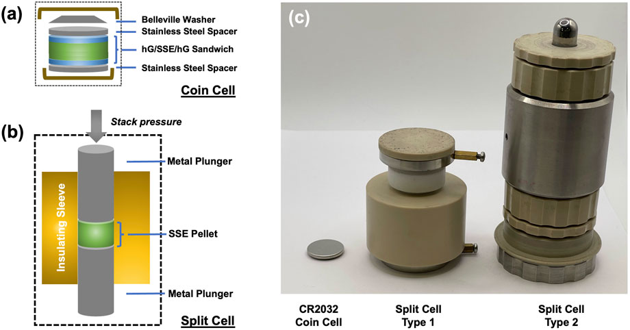
Figure 1. Schematics of using (a) a coin cell with holey graphene-based current collectors or (b) a typical split cell set up for ionic conductivity measurements. Holey graphene-based current collectors were also used for split cell measurements in this work. (c) is a photograph showing a CR2032 coin cell (typical disc diameter 15 mm) and two types of commercially available split cells (Type 1: sleeve inner diameter 15 mm from MTI Corp.; Type 2: sleeve inner diameter 12 mm from rhd Instruments).
To prepare a hG/SSE/hG sandwich disc, a thin aluminum foil disc was first placed at the bottom of the die to prevent the hG powder from adhering to the surface. A layer of hG powder, ∼7.5 mg by weight (∼4.25 mg/cm2), was then added on the top of this foil and spread uniformly by pressing gently with the piston. Then ∼200 mg of the SSE powder (113 mg/cm2) was added on top of this layer, and carefully smoothed with the metal piston to evenly distribute the material. A second layer of hG of the same weight was then spread on the top to cover the SSE surface. The layered architecture was topped by a second aluminum foil disc and cold pressed at ∼200 MPa for 10 min, followed by removal from the die, similar to the SSE-only samples. The aluminum foils were peeled off so the sandwich disc would be freestanding.
After pressing each pellet, the thickness was measured at 5 different locations on each sample using a Mitutoyo digital thickness gauge, and the average thickness was noted. Freestanding hG-only discs of similar total weights were pressed separately, and the thicknesses were measured to obtain the density value (∼0.83 g/cm3). This value and the total amount of hG were used to estimate the thickness contribution of the hG layers in the hG/SSE/hG sandwich discs. These discs were then assembled in a CR2032 coin cell with stainless steel spacers and a Belleville washer as the spring, similar to that of a typical coin cell battery assembly process (all parts were purchased from MTI Corp. or MSE Supplies Co.). The coin cells were placed in an environmental chamber and tested at a temperature range of 0 °C–100 °C in incremental heating steps of 10 °C. At each step, the sample was allowed to remain at the set temperature for a minimum of 30 min before the EIS spectrum was taken. For the coin cell configuration, no extra external stack pressure was applied to the sample. The contact pressure applied on the samples was provided via the Belleville washer and was no more than 2 MPa.
Several commercial split cell systems were tested (Figures 1b,c). In this work, only data using the split cells with the CompreDrive system (rhd instruments GmbH and Co. KG, Germany) is reported. This instrument is programmable and fully automated, and capable of precise temperature and pressure control. The test cell (12-mm inner sleeve diameter, Model 12PEI-DP, rhd Instruments, Figure 1c) is airtight and electrically connected to a channel in the BioLogic VMP3 electrochemical station. According to the manufacturer, the piston consists of 90% tungsten carbide and 10% cobalt with a hardness scale A (HRA) of 91.5–92.0 and grain size of 0.6–0.8 µm.
In the split cell measurements, the neat SSE and the hG/SSE/hG sandwich discs were each prepared and tested in the same cell without removing the materials, similar to most previously reported work using split cells for ionic conductivity measurements (Famprikis et al., 2019; Lee et al., 2021; Wang et al., 2021; Wu et al., 2021; Yu et al., 2021; Janek and Zeier, 2023; Kalnaus et al., 2023). In a typical experiment for a neat SSE disc, 113 mg of the SSE powder (100 mg/cm2) was loaded in the test cell and contacted directly with the metal pistons. For a hG/SSE/hG sandwich disc, ∼7.5 mg of hG (∼6.6 mg/cm2) was placed at the bottom of the cell and carefully spread. The SSE material (113 mg) was added on this layer, and a second layer of hG of the same weight was spread on the top. The top metal piston was placed in direct contact with the second hG layer. Both the neat and sandwich configurations were pressed with a fabrication pressure of 500 MPa. Temperature was held constant at 25 °C and the pressure was decreased from 500 MPa for the fabrication to 2 MPa for the first measurement.
To determine the ionic conductivity, the Nyquist plots from the spectra from coin cell measurements were fit with a Rb-RP circuit using the PyEIS Python package. The resistance of the first resistor (Rb) – representing the bulk impedance–was taken as the ionic resistance, and ionic conductivity (σ) was calculated from this using:
where l and A are the thickness and the area of the pellet, respectively. In the case of the split cell data using CompreDrive, the data was fit to an R0-Rb-RP circuit, with the first resistance representing the resistance of the wiring and equipment setup recommended by the rhd company.
3 Results and discussion
Sulfide-based SSEs are typically of high ionic conductivity at room temperature (>1 mS/cm), and therefore widely used for research in all-solid-state batteries. LPSC may be the most studied sulfide SSE and is commercially available in large quantities at an economic cost (∼$10/g) (Lee et al., 2021; Wang et al., 2021; Wu et al., 2021; Yu et al., 2021). Many other sulfide SSEs are also commercially available; LSnPS and LGPS are selected as additional examples in this work.
Coin cell parts are of low cost, standardized, and commercially available. The standardization, as well as higher testing throughput, should lower testing error across samples and across different research laboratories. Coin cells, once assembled and sealed, can be removed from Ar-filled gloveboxes and conveniently placed in environmental chambers or ambient environments for testing at different temperatures. However, coin cells are so far not a popular option for SSB research because the stack pressure is extremely low and only enabled by a spring or a Belleville washer. Experiments here showed that the full displacement of a typical Belleville washer is equivalent to a pressure of no more than 2 MPa (Lin et al., 2025). Therefore, the actual pressure felt by the unit cells or discs, while difficult to quantify after assembly, could be estimated to be in the range of 0.1–2 MPa. In coin cells, the pressure from the spring is typically further distributed by a piece of flat stainless steel spacer (Figure 1a), which is in direct contact with the cell active components. As long as all components within the coin cells are perfectly aligned, the rigidness of the spacer should allow uniform pressure being applied and thus consistency of subsequent test results.
In order to measure ionic conductivity using coin cells, freestanding SSE discs must be first prepared. Neat LPSC powder adheres to itself well upon compression, forming high quality free-standing discs that could be directly used. To illustrate the effect of conformality of the current collectors, hG was used as the interfacial current collector to prepare robust, freestanding hG/LPSC/hG sandwich discs by sequentially adding hG powder, LPSC powder, and hG powder to the compression die and pressed together. The dry compressible property of hG is unique, as most known carbon materials become extremely fragile and do not hold into a densified structure upon dry compression. In addition, it was previously shown that hG can serve as a dry compressible matrix to host other non-compressible fillers, or sandwich less compressible materials in a layered structure (Plaza-Rivera et al., 2020). The freestanding hG/LPSC/hG disc fabrication takes advantage of this unique property.
The uniqueness of hG is demonstrated in the direct comparison of using a few other common conductive carbon powders for similar sandwich disc fabrication. As shown in Figure 2, the hG/LPSC/hG sandwich disc appears intact and robust. In contrast, the one with VGCF is defective and partially broken off, while the fabrication of carbon/LPSC/carbon with C45 or KB resulted in completely shattered pieces upon removal from the pressing die. hG provides the most robustness to the sandwich architecture while the other carbon powders do not possess the same capability. These carbon powders may still be useful in split cell testing where the discs do not need to be removed from the pressing/testing die, but unsuitable for coin cell testing since the latter requires freestanding discs. Coin cell testing could be more widely adopted due to the availability of standard fabrication accessories and equipment available in most research laboratories, while split cells requiring the pressure jigs are usually custom made and lack common standard practices.
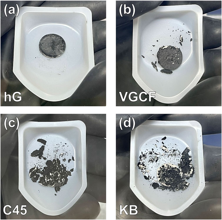
Figure 2. Photographs of the carbon/LPSC/carbon sandwich disc samples fabricated by using various conductive carbon materials: (a) hG, (b) VGCF, (c) C45, and (d) KB. Only the hG/LPSC/hG sandwich disc remained fully intact.
The freestanding neat LPSC and the hG/LPSC/hG discs were assembled in CR2032 coin cells using typical accessories. Stainless steel spacer discs were used on both anode and cathode sides as the current collectors. For the hG/LPSC/hG disc, since hG directly interfaces with LPSC, it serves as the actual conformal current collectors. Each coin cell used a Belleville washer to provide the contact/stack pressure as discussed previously.
As shown in the Nyquist plots from EIS measurements in Figure 3a, the coin cells with the hG/LPSC/hG sandwich exhibited much lower impedance in comparison to the ones with the neat LPSC disc at various temperatures (30 °C, 60 °C, and 90 °C). The bulk impedance values for both samples, often represented by the x-intercept (or linear extension to x-axis of the high frequency data) of the impedance curves, reduce with the increase of temperature, as expected. The ionic conductivity values, calculated from the bulk impedance values and LPSC layer thicknesses, shown in the Arrhenius plot in Figure 3b, exhibit a typical temperature-dependent trend, with the logarithm of the ionic conductivity linearly dependent on the inverse of temperature. The low impedance for the hG/LPSC/hG sandwich discs resulted in much higher ionic conductivity values across the temperatures used. For example, at 30 °C, 60 °C, and 90 °C, the hG/LPSC/hG sandwich discs exhibited values of 1.37, 3.89, and 8.88 mS/cm, while the neat disc resulted values of 0.44, 0.63, and 1.40 mS/cm. Across the entire temperature range surveyed (0 °C–100 °C), the measured ionic conductivity with the hG/LPSC/hG sandwich disc is consistently several times higher than the neat LPSC disc. This is a difference significant enough that could move the validation of a new SSE from being considered highly viable (>1 mS/cm) to marginally viable (<0.5 mS/cm) at low stack pressure conditions in coin cells. Because both discs were prepared with the same fabrication pressure and used the same LPSC powder, the stark difference can only be attributed to the enhanced interfacial contact of the LPSC layer and the hG layers as the current collectors.
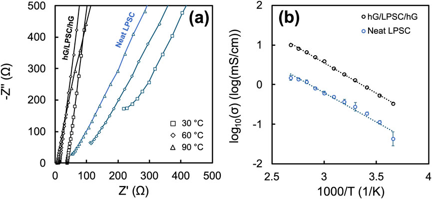
Figure 3. (a) Nyquist plots from coin cell EIS measurements of the neat LPSC and the hG/LPSC/hG sandwich discs at three temperatures – 30 °C, 60 °C, 90 °C; (b) Arrhenius plot from the coin cell EIS measurements of the neat and sandwich discs over 0 °C–100 °C. The data point and the corresponding error bars are the average and standard deviation values from measurements of three different coin cells.
The Arrhenius plots for both the neat LPSC disc and the hG/LPSC/hG sandwich discs exhibited similar slopes, with the activation energies calculated to be 0.29 ± 0.04 eV and 0.30 ± 0.01 eV, respectively. This observation is consistent with the expectation that the use of conformal hG current collectors should not affect the intrinsic Li ion conduction mechanism with the LPSC phase. Each data point for the Arrhenius plots in Figure 3b was an average from three separate experiments of three coin cells. The data for the hG/LPSC/hG discs appears to exhibit much lower error margins and thus more consistent in comparison to the neat LPSC disc.
The surfaces of the neat LPSC vs. hG/LPSC/hG discs both appeared visually uniform. Therefore, the neat LPSC surface and the conformality of the hG layer and the LPSC surface in the sandwich disc were further evaluated by cross-sectional morphological characterizations using microscopy techniques. For the hG/LPSC/hG sandwich disc (Figure 4a), SEM images with EDS data (Figures 4b–d) show a ∼50 µm thick hG layer on both sides of the LPSC layer. The thickness of the hG layer is consistent with the density estimation from the freestanding hG disc discussed previously. At higher magnifications, although the hG-LPSC interfaces are not completely flat, no gaps or pores are observed. In comparison, for the neat LPSC disc (Figure 4c bottom), despite the visually mirror finish, the SEM image of the polished cross-section of the disc revealed that the surfaces contain many protrusions at the microscopic level, with rough domains of ∼10 µm in size, likely templating from the surface of the pressing die spacers. The benefit of the hG current collectors is thus obvious that they allow the rough SSE surface and pores to be filled in by conformal carbon layers, facilitating complete electrical contact.
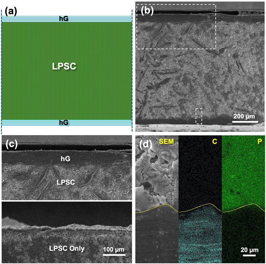
Figure 4. (a) Schematic and (b) cross-sectional SEM of a hG/LPSC/hG sandwich disc. The top and bottom rectangle highlighted regions are magnified and shown in Figure 4c top and Figure 4d, respectively. The cross-sectional view of the surface of a neat LPSC disc is shown in Figure 4c bottom. In Figure 4d, both C and P maps from EDS are shown, representing the hG and LPSC phases, respectively. Dashed lines are guide to the eye showing the conformal interface between the hG and LPSC phases.
To further validate the effect of hG current collectors obtained from the coin cell measurements, both neat and sandwich discs were fabricated and tested in a commercial split cell system with precise temperature and pressure control (CompreDrive and CompreCell, rhd Instruments, Germany). Three different sulfide SSEs were used, including LPSC, LGPS, and LSnPS. In these experiments, the neat SSE powder and the hG/SSE/hG sandwich powder were each pressed to 500 MPa at 25 °C for 10 min to allow for complete densification of the SSEs. The stack pressure was then lowered sequentially until reaching 2 MPa, the lower limit of the equipment. The impedance data was taken at each stack pressure to obtain the ionic conductivity values. As shown in Figure 5, all three sets of samples with different SSEs exhibit similar patterns in that the ionic conductivity values mostly overlap (within 5%–15%) at high stack pressures for the neat and the sandwich discs. In both cases, the initial increase with pressure is due to the densification of solid electrolyte that results in improved solid-solid interfacial contact. The subsequent decrease was due to over-pressurization reduced the ion transport channels within the solid electrolyte (Cronau et al., 2021; Faka et al., 2023). However, the sandwich discs exhibited much higher values than the neat discs at lower stack pressures, as clearly shown in Figures 5d,e emphasizing the lower pressure region. Using the LPSC discs as an example (Figures 5a,d), at 5 MPa, the ionic conductivity value measured for the hG/LPSC/hG sample is 50% higher than the neat LPSC sample (2.29 vs. 1.53 mS/cm). While at the lowest measured stack pressure of 2 MPa, the difference was as high as 150% (2.05 vs. 0.82 mS/cm). The coin cell data from 20 °C/30 °C measurements previously shown in Figure 3 were also plotted for reference by assuming a 0.5 MPa stack pressure. They fit well in the ionic conductivity–pressure trend, suggesting the data from coin cell measurements were highly reliable.
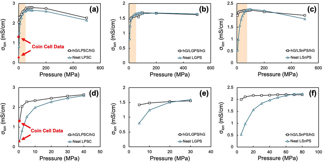
Figure 5. Ionic conductivity values for the neat SSE and the hG/SSE/hG sandwich discs as a function of measuring pressure using a split cell format for (a,d) LPSC, (b,e) LGPS, and (c,f) LSnPS. (a–c) show the entire testing range of 5–500 MPa, while (d–f) show the enlarged low pressure range up to the threshold pressure. Coin cell data for the neat LPSC and hG/LPSC/hG cells are also shown in (a) and (d) to compare with the split cell data.
The same trend was observed for both LGPS (Figures 5b,e) and LSnPS (Figures 5c,f), except for the threshold pressures (where the value difference diminishes) are somewhat different. From Figures 5d–f, it appears that the threshold pressure for LPSC, LGPS, and LSnPS were ∼40, 20, and 70 MPa, respectively, below which the effect of conformal hG current collector becomes prominent. From the current data, the mechanism is not entirely clear on why there is a difference in the threshold pressure. Presumably, the Young’s modulus and the grain size of the SSEs should both play a role in this threshold, but the values of these three types of SSEs were all similar. More detailed studies are required for a complete understanding. Nonetheless, the data obtained from precise stack pressure control over a large range validates that the conformal effect of hG current collectors is broadly applicable to the ionic conductivity measurement across many sulfide-based SSE systems.
4 Conclusion
In this work, it is demonstrated that robust, freestanding SSE pellets sandwiched by hG current collectors can be prepared and encased in coin cells for consistent ionic conductivity measurements. The measured values were an order of magnitude higher than those using neat SSE discs. The trend is confirmed by using equipment with accurate pressure control, where the measured ionic conductivity values with hG current collectors increase by 150% and 50% at 2 MPa and 5 MPa, respectively, in comparison to the use of neat SSE discs and regular metal current collectors. Microscopy data reveals that the interface between the hG and SSE was highly conformed, while the neat SSE discs usually exhibited microscopic roughness that could be detrimental for accurate low stack pressure measurements. The use of hG could thus enable more accurate and standardized testing of ionic conductivity, even when using coin cells. The results also provide insights with respect to Li ion conduction in the solid-state and the interface between the SSE and the electrodes at low stack pressures, which is key for future practical SSBs.
Data availability statement
The original contributions presented in the study are included in the article, further inquiries can be directed to the corresponding author.
Author contributions
CS: Data curation, Formal Analysis, Investigation, Methodology, Visualization, Writing – original draft, Writing – review and editing. LD: Data curation, Investigation, Writing – review and editing. JK: Data curation, Formal Analysis, Writing – review and editing. VY: Writing – review and editing. JS: Writing – review and editing. DD: Writing – review and editing. RV: Project administration, Writing – review and editing. YL: Conceptualization, Data curation, Formal Analysis, Funding acquisition, Investigation, Methodology, Project administration, Resources, Supervision, Validation, Writing – review and editing, Writing – original draft.
Funding
The author(s) declare that financial support was received for the research and/or publication of this article. This work was part of NASA Solid State Architecture Batteries for Enhanced Rechargeability and Safety (SABERS) project supported by Convergent Aeronautics Solutions (CAS) and Transformational Tools and Technologies (TTT) projects.
Acknowledgments
CS was a NASA Office of STEM Engagement Intern supported by CAS and the NASA Minority University Research and Education Program (MUREP). LD and VY were sponsored through the research science engineering services (RSES) contract number 80LARC23DA003 with the Analytical Mechanics Associates.
Conflict of interest
Authors LD and VY were employed by Analytical Mechanics Associates.
The remaining authors declare that the research was conducted in the absence of any commercial or financial relationships that could be construed as a potential conflict of interest.
The author(s) declared that they were an editorial board member of Frontiers, at the time of submission. This had no impact on the peer review process and the final decision.
Generative AI statement
The author(s) declare that no Generative AI was used in the creation of this manuscript.
Any alternative text (alt text) provided alongside figures in this article has been generated by Frontiers with the support of artificial intelligence and reasonable efforts have been made to ensure accuracy, including review by the authors wherever possible. If you identify any issues, please contact us.
Publisher’s note
All claims expressed in this article are solely those of the authors and do not necessarily represent those of their affiliated organizations, or those of the publisher, the editors and the reviewers. Any product that may be evaluated in this article, or claim that may be made by its manufacturer, is not guaranteed or endorsed by the publisher.
Footnotes
1Specific vendor and manufacturer names are explicitly mentioned only to accurately describe the materials and hardware used in this study. The use of vendor and manufacturer names does not imply an endorsement by the U.S. Government nor does it imply that the specified material or equipment is the best available.
References
Allen, M. J., Tung, V. C., and Kaner, R. B. (2010). Honeycomb carbon: a review of graphene. Chem. Rev. 110, 132–145. doi:10.1021/cr900070d
Armand, M., and Tarascon, J.-M. (2008). Building better batteries. Nature 451, 652–657. doi:10.1038/451652a
Cronau, M., Szabo, M., König, C., Wassermann, T. B., and Roling, B. (2021). How to measure a reliable ionic conductivity? The stack pressure dilemma of microcrystalline sulfide-based solid electrolytes. ACS Energy Lett. 6, 3072–3077. doi:10.1021/acsenergylett.1c01299
Deng, R., Ke, B., Xie, Y., Cheng, S., Zhang, C., Zhang, H., et al. (2023). All-solid-state thin-film lithium-sulfur batteries. Nano-Micro Lett. 15, 73. doi:10.1007/s40820-023-01064-y
Doux, J.-M., Yang, Y., Tan, D. H. S., Nguyen, H., Wu, E. A., Wang, X., et al. (2020). Pressure effects on sulfide electrolytes for all solid-state batteries. J. Mater. Chem. A 8, 5049–5055. doi:10.1039/C9TA12889A
Evarts, E. C. (2015). Lithium batteries: to the limits of lithium. Nature 526, S93–S95. doi:10.1038/526S93a
Faka, V., Agne, M. T., Till, P., Bernges, T., Sadowski, M., Gautam, A., et al. (2023). Pressure dependence of ionic conductivity in site disordered lithium superionic argyrodite Li6PS5Br. Energy Adv. 2, 1915–1925. doi:10.1039/D3YA00424D
Famprikis, T., Canepa, P., Dawson, J. A., Islam, M. S., and Masquelier, C. (2019). Fundamentals of inorganic solid-state electrolytes for batteries. Nat. Mater. 18, 1278–1291. doi:10.1038/s41563-019-0431-3
Greenburg, L. C., Plaza-Rivera, C. O., Kim, J.-W., Connell, J. W., and Lin, Y. (2021). Architecture transformations of ultrahigh areal capacity air cathodes for lithium-oxygen batteries. Batter. and Supercaps 4, 120–130. doi:10.1002/batt.202000201
Haddon, R. C. (2013). Graphene – the mother of two-dimensional (2-D) materials. Acc. Chem. Res. 46, 2191–2192. doi:10.1021/ar4002203
Han, X., Yang, Z., Zhao, B., Zhu, S., Zhou, L., Dai, J., et al. (2017). Compressible, dense, three-dimensional holey graphene monolithic architecture. ACS Nano 11, 3189–3197. doi:10.1021/acsnano.7b00227
Janek, J., and Zeier, W. G. (2023). Challenges in speeding up solid-state battery development. Nat. Energy 8, 230–240. doi:10.1038/s41560-023-01208-9
Kalnaus, S., Dudney, N. J., Westover, A. S., Herbert, E., and Hackney, S. (2023). Solid-state batteries: the critical role of mechanics. Science 381, eabg5998. doi:10.1126/science.abg5998
Ke, B., and Wang, X. (2025). Integratable all-solid-state thin-film microbatteries. PNAS 122, e2415693122. doi:10.1073/pnas.2415693122
Ke, B., Cheng, S., Zhang, C., Li, W., Zhang, J., Deng, R., et al. (2024). Low-temperature flexible integration of all-solid-state thin-film lithium batteries enabled by spin-coating electrode architecture. Adv. Energy Mater. 14, 2303757. doi:10.1002/aenm.202303757
Lee, J., Lee, T., Char, K., Kim, K. J., and Choi, J. W. (2021). Issues and advances in scaling up sulfide-based all-solid-state batteries. Acc. Chem. Res. 54, 3390–3402. doi:10.1021/acs.accounts.1c00333
Lin, Y., Han, X., Campbell, C. J., Kim, J.-W., Zhao, B., Luo, W., et al. (2015). Holey graphene nanomanufacturing: structure, composition, and electrochemical properties. Adv. Funct. Mater. 25, 2920–2927. doi:10.1002/adfm.201500321
Lin, Y., Liao, Y., Chen, Z., and Connell, J. W. (2017). Holey graphene: a unique structural derivative of graphene. Mater. Res. Lett. 5, 209–234. doi:10.1080/21663831.2016.1271047
Lin, Y., Plaza-Rivera, C. O., Hu, L., and Connell, J. W. (2022). Scalable dry-pressed electrodes based on holey graphene. Acc. Chem. Res. 55, 3020–3031. doi:10.1021/acs.accounts.2c00457
Lin, Y., Somervill, L. G., Rashid, R., Ledesma, R. I., Kang, J. H., Kavanagh, A. R., et al. (2025). Toward 500 Wh Kg−1 in specific energy with ultrahigh areal capacity all-solid-state lithium–sulfur batteries. Small 21, 2409536. doi:10.1002/smll.202409536
Liu, J., Bao, Z., Cui, Y., Dufek, E. J., Goodenough, J. B., Khalifah, P., et al. (2019). Pathways for practical high-energy long-cycling lithium metal batteries. Nat. Energy 4, 180–186. doi:10.1038/s41560-019-0338-x
Plaza-Rivera, C. O., Walker, B. A., Tran, N. X., Viggiano, R. P., Dornbusch, D. A., Wu, J. J., et al. (2020). Dry pressing neat active materials into ultrahigh mass loading sandwich cathodes enabled by holey graphene scaffold. ACS Appl. Energy Mater. 3, 6374–6382. doi:10.1021/acsaem.0c00582
Wang, C., Liang, J., Zhao, Y., Zheng, M., Li, X., and Sun, X. (2021). All-solid-state lithium batteries enabled by sulfide electrolytes: from fundamental research to practical engineering design. Energy Environ. Sci. 14, 2577–2619. doi:10.1039/D1EE00551K
Wu, J., Liu, S., Han, F., Yao, X., and Wang, C. (2021). Lithium/sulfide all-solid-state batteries using sulfide electrolytes. Adv. Mater. 33, 2000751. doi:10.1002/adma.202000751
Xiao, Y., Wang, Y., Bo, S.-H., Kim, J. C., Miara, L. J., and Ceder, G. (2020). Understanding interface stability in solid-state batteries. Nat. Rev. Mater 5, 105–126. doi:10.1038/s41578-019-0157-5
Xie, W., Deng, Z., Liu, Z., Famprikis, T., Butler, K. T., and Canepa, P. (2024). Effects of grain boundaries and surfaces on electronic and mechanical properties of solid electrolytes. Adv. Energy Mater. 14, 2304230. doi:10.1002/aenm.202304230
Yang, H., and Wu, N. (2022). Ionic conductivity and ion transport mechanisms of solid-state lithium-ion battery electrolytes: a review. Energy Sci. and Eng. 10, 1643–1671. doi:10.1002/ese3.1163
Keywords: solid state batteries, stack pressure, ionic conductivity, holey graphene, current collector
Citation: Scrudder CH, Das L, Kang JH, Yamakov VI, Su J, Dornbusch DA, Viggiano RP and Lin Y (2025) Ionic conductivity measurements of solid state electrolytes with coin cells enabled by dry-pressed holey graphene current collectors. Front. Energy Res. 13:1684653. doi: 10.3389/fenrg.2025.1684653
Received: 12 August 2025; Accepted: 30 September 2025;
Published: 03 November 2025.
Edited by:
Bin Liu, SES AI Corporation, United StatesReviewed by:
Xinghui Wang, Fuzhou University, ChinaChakrit Sriprachuabwong, National Energy Technology Center, Thailand
Copyright © 2025 Scrudder, Das, Kang, Yamakov, Su, Dornbusch, Viggiano and Lin. This is an open-access article distributed under the terms of the Creative Commons Attribution License (CC BY). The use, distribution or reproduction in other forums is permitted, provided the original author(s) and the copyright owner(s) are credited and that the original publication in this journal is cited, in accordance with accepted academic practice. No use, distribution or reproduction is permitted which does not comply with these terms.
*Correspondence: Yi Lin, eWkubGluLTFAbmFzYS5nb3Y=