 Jun Wang
- Department of Electronic Information, Hunan International Economics University, Changsha, Hunan, China
The inherent problem of neutral-point potential imbalance in three-level neutral-point-clamped (3L-NPC) converters increases the risk of overvoltage in switching devices, causes increased output harmonic content, and seriously affects the performance and safe operation of the converters. To achieve neutral-point voltage balance control, this article proposes a neutral-point voltage balance control method based on zero-sequence component injection. The proposed method has the advantage of low computational complexity and can achieve balance control of neutral-point potential under various operation conditions. Finally, the experimental results validated the correctness and effectiveness of the presented method.
Introduction
Compared with the traditional two-level inverter, the three-level neutral-point-clamped (3L-NPC) converter has the advantages of large capacity, high output voltage, and low output current harmonic content; therefore, it is widely used in new energy power generation, medium–high voltage, and high-power applications (Lewicki et al., 2024; Lee et al., 2025; Sarker et al., 2024). However, due to its topological structure, there is a problem of neutral-point potential imbalance. The neutral-point potential imbalance not only leads to increased output harmonics but also causes overvoltage damage of power devices, which affects the output performance and safety of the converter (Guo et al., 2022).
With the deepening research on the problem of neutral-point voltage (NPV) balance, some NPV balance strategies have been proposed, mainly divided into hardware balance methods and software balance methods. The former uses additional devices or circuits to balance the neutral-point potential, which requires additional hardware, such as increasing the capacitance of the DC-link capacitors or adding additional voltage equalization circuits. The hardware balance methods increase the system’s volume and maintenance costs and also reduce the power density of the system (Von Jouanne et al., 2002; Rivera et al., 2015). The software balancing scheme achieves balance control of the neutral-point potential by improving the control algorithm. Many improved pulse width modulation (PWM) techniques have been developed, which are mainly classified as space vector PWM (SVPWM) and carrier-based PWM (CBPWM) (Chen et al., 2021).
The balance scheme based on SVPWM utilizes the principle that different vectors have different effects on the neutral-point potential to achieve NPV balance (Liu et al., 2018; Jiang et al., 2020). A vector allocation factor is introduced to adjust the action time of two small vectors. It uses the opposite effect of small vectors on the neutral-point potential to achieve NPV balance (Liu et al., 2018). However, it increases the output harmonic content, and the SVPWM method involves complex trigonometric function calculation and sector judgment. The nearest triangle vectors (NTV) SVM method realizes the NPV balance by selecting proper redundant small vectors (Yamanaka et al., 2002). However, this cannot operate effectively under the conditions of high modulation index and low power factor.
The commonly used methods in CBPWM include dual-modulation signals and zero-sequence voltage injection. The former injects appropriate offset signals into the dual reference signal to generate dual-modulation signals, balancing the DC-link voltages. In Giri et al. (2017) and Giri et al. (2019), dual-modulation signals are generated to balance the capacitor voltage and eliminate its ripple. However, generation of the offset signals relies on real-time acquisition of the voltage vector angles, which involves calculation of inverse trigonometric functions and requires high computational resource overhead. Another approach to achieving NPV balance is to inject a zero-sequence voltage signal into the original modulation signals (Wang et al., 2016; Mukherjee et al., 2019). Zero-sequence voltage affects the direction and magnitude of neutral-point current, thereby achieving NPV balance. Wang et al. (2016) propose a carrier-based PWM strategy with zero-sequence voltage injected for the 3L-NPC inverter, which achieves NPV balancing by decomposing the modulation wave in a specific mode after injecting zero-sequence voltage. This method effectively expands the NPV equilibrium region, but the decomposition of modulated waves involves the calculation of many trigonometric functions, which undoubtedly increases the computational burden. In addition, this method requires prior knowledge of the load power factor, which is difficult to obtain in some practical applications. In Li et al. (2018), a triangle carrier-based discontinuous PWM (TCB-DPWM) method is proposed, which improves system efficiency. However, this method requires calculating the sign of the three-phase voltage and calculating the average neutral-point current within a switching period, which requires multiple multiplication, division, addition, and other operations on the voltage and current. In Zhang et al. (2017) and Mukherjee et al. (2019), the injected zero-sequence voltage signals are generated by a closed-loop controller, which is designed to regulate the deviation of the two DC-link capacitor voltages to be zero. However, the NPV balancing performances, such as steady-state NPV fluctuations and balancing speed, depend on the introduced discontinuity control parameter (Mukherjee et al., 2019).
Some easy-to-implement methods with relatively low computational burden have been proposed (Wan et al., 2021; Alsofyani and Lee, 2021; Wang et al., 2020). The calculation of ideal NP current (Alsofyani and Lee, 2021) and hysteresis capacitance voltage bands (Wang et al., 2020) requires prior knowledge of capacitor parameters, which may affect the performance in cases of unbalanced capacitor parameters or parameter drift caused by aging or heat. The proposed method takes into account the situation of capacitor parameter imbalance.
The neutral-point potential balance is a problem that must be addressed when applying a 3L-NPC converter. Although many scholars have proposed various solutions, most existing solutions lack low computational complexity characteristics. Therefore, this article proposes a neutral-point voltage balance control method based on zero-sequence component injection for 3L-NPC converters. Compared with most existing CBPWM schemes, the proposed method has the advantage of low computational complexity and good adaptability to operation conditions.
Materials and methods
Figure 1 shows the topology diagram of the 3L-NPC converter. C1 and C2 are the upper and lower DC-link capacitors, and u1 and u2 are the voltages of the DC-link capacitors. Each phase of the 3L-NPC converter can generate three states, which are defined as “P,” “O,” and “N.”
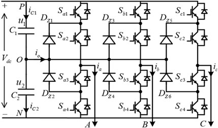
Figure 1. Topology of the 3L-NPC converter.
Based on Kirchhoff’s current law, the averaged neutral-point current can be obtained as Equation 1:
where ix (x = a,b,c) is the phase current, and dxO {x = a,b,c} is the duty cycle of “O.” iC1 and iC2 are the currents of each capacitor.
It can be seen that the averaged neutral-point current within a switching period is the sum of the instantaneous values of the phase currents in the “O” state of the three-phase system.
NPV balance control method
This section proposes a zero-sequence voltage injection method based on the phase disposition pulse width modulation (PD-PWM) to suppress the neutral-point potential fluctuation of 3L-NPC converters. The averaged neutral-point current can be controlled by injecting zero-sequence voltage components into the three-phase modulation signals to change the duty cycle of state “O.” First, the compensation zero-sequence voltage calculation method of the proposed method is introduced. In addition, a controller is designed to achieve closed-loop control of the neutral-point potential.
The basic principles
The proposed NPV balancing method includes two key procedures:
1. Inject the zero-sequence components u0.
To improve the utilization rate of DC-link voltage, a zero-sequence component is injected into the original three-phase modulation signals. The zero-sequence voltage is designed as Equation 2:
where ua, ub, and uc indicate the original three-phase modulation signals.
The obtained three-phase reference voltage can be expressed as Equation 3:
1. Calculate
1. Calculate the compensated zero-sequence voltage ucom.
According to the proposed neutral-point potential compensation strategy in this article, calculate the required compensation zero-sequence component and inject it into the three-phase reference voltage modulation signals to achieve control of neutral-point potential balance. The final modulation voltage is expressed as Equation 6:
Duty cycle calculations
The calculation of the duty cycles varies under different carrier modulation strategies. This section derives the PD-PWM as an example. Under the PD-PWM modulation strategy, the modified modulation signals within each switching period exhibit the following four situations based on their amplitude, as shown in Figure 2.
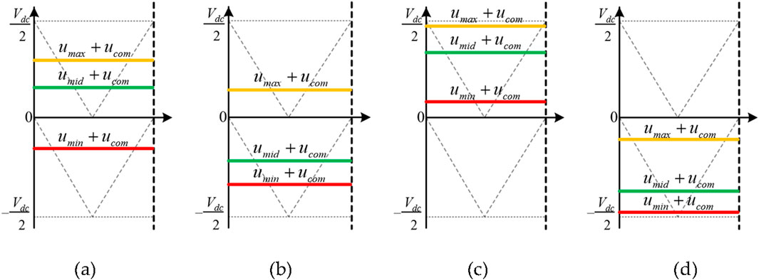
Figure 2. Modified modulation signals under PD-PWM. (a) Case I. (b) Case II. (c) Case III. (d) Case IV.
When
When
Normalize the compensated modulation signals, and the corresponding duty cycles are expressed as Equation 11:
where subscripts “P” and “N” indicate the output voltage state.
The compensated zero-sequence voltage
The averaged neutral-point current within a modulation period is expressed as Equation 12:
It can be observed that adjusting the compensated modulated signal
The averaged neutral-point current corresponding to the four types of modified modulation signals is analyzed as Equations 13–16:
1.
2.
3.
4.
where
The analysis reveals that the averaged neutral-point current contains compensated zero-sequence components when the compensated modulation signal is as shown in Figure 2 in Case I and Case II. The signs of three-phase modulation signals are not the same, which means that the averaged neutral-point current can be compensated and controlled by changing the compensating zero-sequence component, thereby controlling the neutral-point potential. When the compensated modulation signal is in Case III and Case IV, as shown in Figure 2, the signs of the three-phase modulation signals are the same, and the averaged neutral-point current does not contain the compensated zero-sequence component. This indicates that injecting zero-sequence components does not affect the averaged neutral-point current, thus making it impossible to control the neutral-point potential. Therefore, when using the compensation zero-sequence component injection to achieve balanced control of neutral-point potential, it is necessary to avoid the situation where the modulation signals maintain consistent polarity after injecting the zero-sequence component.
The averaged neutral-point current after injecting the compensating zero-sequence component is expressed as Equation 17:
Assume that
According to (18), there are three parts included in the averaged neutral-point current: 1) The sum of the grid side currents. This component is zero in a three-phase three-line system. 2) The second part is the neutral-point fluctuation current generated by the PD-PWM modulation strategy, represented as id. This item is uncontrollable and the fundamental cause of neutral-point potential fluctuations. 3) The third part is the compensation current generated by injecting the zero-sequence component, represented as icom. The proposed method utilizes icom to compensate for the neutral-point fluctuation current id, thereby controlling the averaged neutral-point current.
The averaged neutral-point current for other modulation voltages and compensated zero-sequence voltages can be derived similarly. Therefore, the averaged neutral-point current under different situations is summarized in Table 1.
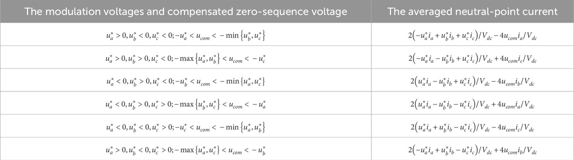
Table 1. The averaged neutral-point current under different situations.
To avoid the situation where the modulation signals maintain the same polarity after injecting the zero-sequence component, the compensation voltage must meet Equation 19:
According to Equations 13, 14, it can be seen that the expression of the compensating zero-sequence component is related to the sign of
1. When
2. When
Therefore, the control block diagram of the compensation zero-sequence component is designed as shown in Figure 3.
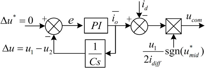
Figure 3. Control block diagram for compensating zero-sequence component.
Where
The required compensation zero-sequence component and phase current sign relationship for different neutral-point potential fluctuations are shown in Table 2. It can be concluded that the sign of the compensating zero-sequence component is related to the fluctuation of neutral-point potential and the sign of the phase current involved in generating the compensating neutral-point current. From the above derivation, the sign of the modulation signal after adding the compensating zero-sequence component determines the phase current used to generate the compensating neutral-point current. Therefore, the sign of the required compensating zero-sequence component can be obtained.
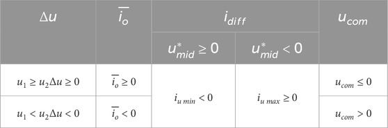
Table 2. The required compensation zero-sequence component and phase current sign relationship for different neutral-point potential fluctuations.
Therefore, the expression for the compensation zero-sequence component can be obtained as Equation 23:
where kp and ki are the proportional coefficient and integral coefficient of the proportional-integral (PI) controller, respectively.
In summary, the flow chart of the proposed neutral-point voltage balancing method is shown in Figure 4.
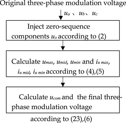
Figure 4. Flow chart of the proposed neutral-point voltage balancing method.
Discussion
The experimental prototype of the 3L-NPC converter is shown in Figure 5, and the main parameters are listed in Table 3.
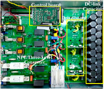
Figure 5. Experimental setup of 3L-NPC converters.
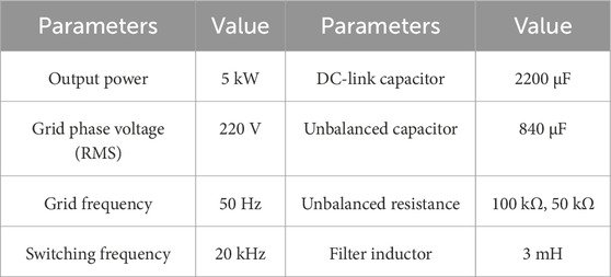
Table 3. Parameters of the experimental setup.
The experimental results of the proposed control method under unbalanced capacitance are shown in Figure 6. The experimental results showed that when there is a difference in the DC-link capacitance of the inverter, the proposed neutral-point potential balance control method can effectively balance the neutral-point potential. The corresponding total harmonic distortion (THD) values of the currents are 3.98%. The THD is smaller than 5%, which meets IEEE Std. 519-2014. The DC capacitor voltage ripple is less than 1.5 V in the steady state, indicating that the proposed method has good steady-state performance.
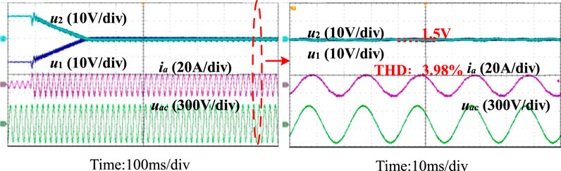
Figure 6. Experimental results under an unbalanced capacitance condition.
Figure 7 shows the experimental waveforms under unbalanced equivalent leakage current (unbalanced parallel resistance simulates unbalanced equivalent leakage current). The experimental results showed that when there is a difference in the equivalent leakage current of the DC-link capacitors, the presented method can also effectively balance the neutral-point potential.

Figure 7. Experimental results of an unbalanced equivalent leakage current condition.
Figure 8 shows the experimental results of the proposed method under unbalanced capacitance and with a power factor of 0.7. It can be observed that after applying the proposed neutral-point potential balance control method, even when the inverter operates at a non-unity power factor, it can effectively balance the neutral-point potential caused by the difference in DC-link capacitance.
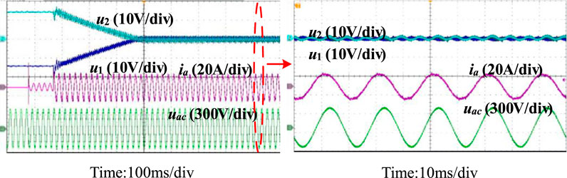
Figure 8. Experimental results of the proposed method under unbalanced capacitance with a power factor of 0.7.
A comparison between the proposed method and other existing methods is shown in Table 4. The zero-sequence voltage injection method based on modulation wave decomposition involves the calculation of many trigonometric functions. The model predictive control (MPC) method based on virtual space vectors requires the calculation of a cost function, which has strong parameter dependence, which is not expected in practical applications. In addition, the MPC method involves the selection of weight factors. In contrast, the proposed method has a relatively smaller computational burden and is not dependent on circuit parameters.
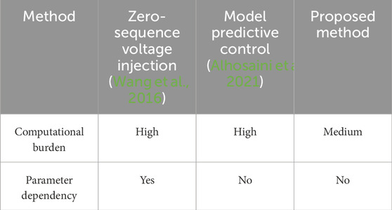
Table 4. Comparison of the existing methods and the proposed method.
Conclusion
This article proposes a neutral-point potential balance control method based on zero-sequence component injection to address the issue of neutral-point potential imbalance in 3L-NPC converters. The basic principle and the compensation zero-sequence voltage calculation of the method are introduced. Based on the relationship between the averaged neutral-point current and the neutral-point potential, a neutral-point potential balance controller is designed. Finally, a 3L-NPC converter prototype is developed to verify the feasibility of the proposed neutral-point potential balance control method under the conditions of unbalanced DC-link capacitance and unbalanced equivalent leakage current. The experimental results show that the developed control method can effectively balance the neutral-point potential with hardware differences under different operating conditions, ensuring safe and stable operation of the system.
Data availability statement
The original contributions presented in the study are included in the article/supplementary material; further inquiries can be directed to the corresponding author.
Author contributions
JW: Investigation, Writing – review and editing, Writing – original draft, Validation, Methodology, Formal Analysis.
Funding
The author(s) declare that no financial support was received for the research and/or publication of this article.
Conflict of interest
The author declares that the research was conducted in the absence of any commercial or financial relationships that could be construed as a potential conflict of interest.
Generative AI statement
The author(s) declare that no Generative AI was used in the creation of this manuscript.
Any alternative text (alt text) provided alongside figures in this article has been generated by Frontiers with the support of artificial intelligence and reasonable efforts have been made to ensure accuracy, including review by the authors wherever possible. If you identify any issues, please contact us.
Publisher’s note
All claims expressed in this article are solely those of the authors and do not necessarily represent those of their affiliated organizations, or those of the publisher, the editors and the reviewers. Any product that may be evaluated in this article, or claim that may be made by its manufacturer, is not guaranteed or endorsed by the publisher.
References
Alhosaini, W., Diao., F., Mahmud, M. H., Wu, Y., and Zhao, Y. (2021). A virtual space vector-based model predictive control for inherent DC-Link voltage balancing of three-level T-Type converters. IEEE J. Emerg. Sel. Top. Power Electron. 9, 1751–1764. doi:10.1109/jestpe.2020.3002192
Alsofyani, I. M., and Lee, K.-B. (2021). Simple capacitor voltage balancing for three-level NPC inverter using discontinuous PWM method with hysteresis neutral-point error band. IEEE Trans. Power Electron. 36, 12490–12503. doi:10.1109/tpel.2021.3074957
Chen, F., Qiao, W., Wang, H., and Qu, L. A. (2021). A simple zero-sequence voltage injection method for carrier-based pulsewidth modulation of the three-level NPC inverter. IEEE J. Emerg. Sel. Top. Power Electron. 9, 4687–4699. doi:10.1109/jestpe.2020.3012726
Giri, S.Kr., Chakrabarti, S., Banerjee, S., and Chakraborty, C. (2017). A carrier-based PWM scheme for neutral point voltage balancing in three-level inverter extending to full power factor range. IEEE Trans. Ind. Electron. 64, 1873–1883. doi:10.1109/tie.2016.2624721
Giri, S. K., Banerjee, S., and Chakraborty, C. (2019). An improved modulation strategy for fast capacitor voltage balancing of three-level NPC inverters. IEEE Trans. Ind. Electron. 66, 7498–7509. doi:10.1109/tie.2018.2880723
Guo, F., Yang, T., Li, C., Bozhko, S., and Wheeler, P. (2022). Active modulation strategy for capacitor voltage balancing of three-level neutral-point-clamped converters in high-speed drives. IEEE Trans. Ind. Electron. 69, 2276–2287. doi:10.1109/tie.2021.3065605
Jiang, W., Wang, P., Ma, M., Wang, J., Li, J., Li, L., et al. (2020). A novel virtual space vector modulation with reduced common-mode voltage and eliminated neutral point voltage oscillation for neutral point clamped three-level inverter. IEEE Trans. Ind. Electron. 67, 884–894. doi:10.1109/tie.2019.2899564
Lee, D.-J., Choi, J.-H., and Choi, U.-M. (2025). Reliability improved discontinuous pulse width modulation for NPC inverters operated at high modulation index. IEEE Trans. Power Electron. 40, 9876–9888. doi:10.1109/tpel.2025.3547374
Lewicki, A., Kondratenko, D., and Odeh, C. I. (2024). Hybridized PWM strategy for Three- and multiphase three-level NPC inverters. IEEE Trans. Ind. Electron. 71, 8279–8290. doi:10.1109/tie.2023.3321999
Li, K., Wei, M., Xie, C., Deng, F., Guerrero, J. M., and Vasquez, J. C. (2018). Triangle carrier-based DPWM for three-level NPC inverters. IEEE J. Emerg. Sel. Top. Power Electron. 6, 1966–1978. doi:10.1109/jestpe.2018.2812704
Liu, G., Wang, D., Wang, M., Zhu, C., and Wang, M. (2018). Neutral-point voltage balancing in three-level inverters using an optimized virtual space vector PWM with reduced commutations. IEEE Trans. Ind. Electron. 65, 6959–6969. doi:10.1109/tie.2018.2798565
Mukherjee., S., Giri, S. K., and Banerjee, S. (2019). A flexible discontinuous modulation scheme with hybrid capacitor voltage balancing strategy for three-level NPC traction inverter. IEEE Trans. Industrial Electron. 66, 3333–3343. doi:10.1109/tie.2018.2851967
Rivera, S., Wu, B., Kouro, S., Yaramasu, V., and Wang, J. (2015). Electric vehicle charging station using a neutral point clamped converter with bipolar DC bus. IEEE Trans. Ind. Electron. 62, 1999–2009. doi:10.1109/tie.2014.2348937
Sarker, R., Bhattacharya, A., Debnath, S., Castillo-Atoche, A., and Datta, A. (2024). A novel FPGA-driven HD-SPWM architecture with zero-sequence voltage insertion strategy for three-level NPC inverter. IEEE Trans. Ind. Inf. 20, 10814–10824. doi:10.1109/tii.2024.3393566
Von Jouanne, A., Dai, S., and Zhang, H. A. (2002). A multilevel inverter approach providing DC-link balancing, ride-through enhancement, and common-mode voltage elimination. IEEE Trans. Ind. Electron. 49, 739–745. doi:10.1109/tie.2002.801233
Wan., W., Duan, S., Chen, C., and Yu, T. (2021). A hybrid control method for neutral-point voltage balancing in three-level inverters. IEEE Trans. Power Electron. 36, 8575–8582. doi:10.1109/tpel.2021.3051044
Wang, Z., Cui, F., Zhang, G., Shi, T., and Xia, C. (2016). Novel carrier-based PWM strategy with zero-sequence voltage injected for three-level NPC inverter. IEEE J. Emerg. Sel. Top. Power Electron. 4, 1442–1451. doi:10.1109/jestpe.2016.2591618
Wang, J., Yuan, X., Dagan, K. J., and Bloor, A. (2020). Optimal neutral-point voltage balancing algorithm for three-phase three-level converters with hybrid zero-sequence signal injection and virtual zero-level modulation. IEEE Trans. Industry Appl. 56, 3865–3878. doi:10.1109/tia.2020.2983659
Yamanaka, K., Hava, A. M., Kirino, H., Tanaka, Y., Koga, N., and Kume, T. (2002). A novel neutral point potential stabilization technique using the information of output current polarities and voltage vector. IEEE Trans. Ind. Appl. 38, 1572–1580. doi:10.1109/tia.2002.804761
Keywords: three-level neutral-point-clamped converter, zero-sequence component injection, neutral-point voltage balance, NPV balance control method, compensated zero-sequence voltage
Citation: Wang J (2025) A neutral-point voltage balance control method for 3L-NPC converters. Front. Energy Res. 13:1688128. doi: 10.3389/fenrg.2025.1688128
Received: 18 August 2025; Accepted: 20 October 2025;
Published: 26 November 2025.
Edited by:
Marif Daula Siddique, Swinburne University of Technology, AustraliaReviewed by:
Ahmed Hussein, INESC TEC Institute for Systems and Computer Engineering, Technology and Science, PortugalNithin Kolli, North Carolina State University, United States
Copyright © 2025 Wang. This is an open-access article distributed under the terms of the Creative Commons Attribution License (CC BY). The use, distribution or reproduction in other forums is permitted, provided the original author(s) and the copyright owner(s) are credited and that the original publication in this journal is cited, in accordance with accepted academic practice. No use, distribution or reproduction is permitted which does not comply with these terms.
*Correspondence: Jun Wang, bGlhb3poX2hpZXVAc2luYS5jbg==