Your new experience awaits. Try the new design now and help us make it even better

ORIGINAL RESEARCH article

Front. Energy Res., 10 November 2025

Sec. Electrochemical Energy Storage

Volume 13 - 2025 | https://doi.org/10.3389/fenrg.2025.1689813

This article is part of the Research TopicAdvances in Battery TechnologiesView all 5 articles

Robust H-infinity control of a two-phase interleaved boost converter for second-life battery integration in battery energy storage systems

  • 1Department of Electrical Engineering, College of Engineering, Jouf University, Sakaka, Saudi Arabia
  • 2Electrical Engineering Department, College of Engineering, Prince Sattam Bin Abdulaziz University, Wadi Al-Dawasir, Saudi Arabia
  • 3Department of Electrical Engineering, Yanbu Industrial College, Yanbu Alsinaiyah, Almadina, Saudi Arabia

Integrating second-life batteries (SLBs) into energy storage systems (ESSs) offers a sustainable and cost-effective solution for extending battery utility. However, the inherent uncertainties and performance variations of these aged batteries present significant challenges in maintaining system stability and efficiency. Hence, this work introduces a robust control strategy employing an H-infinity H controller to regulate a two-phase interleaved boost (IBC) converter interfacing SLBs. The IBC topology effectively steps up the output voltage of SLBs while reducing current ripple and enhancing overall system performance. Also, the developed H control, combined with the IBC, ensures resilience against system uncertainties and load variations, which are common in applications involving SLBs. Extensive simulation results demonstrate that the proposed H control achieves robust output voltage during transient and parameters uncertainties, when compared to classical PI controller. This validates the proposed system suitability for integrating SLBs into modern battery energy storage applications. The proposed H controller demonstrated over 50% reduction in steady-state output ripples across various tested conditions, exhibited strong robustness under severe parameter mismatches, and achieved over 40% faster dynamic response compared to the conventional PI controller. These results validate the proposed system’s suitability for integrating SLBs into modern battery energy storage applications.

1 Introduction

Battery energy storage systems (BESSs) have become increasingly essential in modern power grids due to the rapid growth of intermittent renewable energy sources (RESs) such as solar and wind power. These BESSs provide efficient storage solutions necessary for maintaining grid stability and reliability (Zhao et al., 2025; Lakshmi and Marimuthu, 2025). Hence, BESS addresses this intermittency by storing excess energy during periods of high generation and releasing it when demand peaks or generation drops. Thus, it effectively contributes to supply-demand balancing and enhances grid reliability. Furthermore, BESS improves grid resilience by providing essential ancillary support such as frequency regulation, voltage regulation, and rapid response during grid disturbances (Li et al., 2025; Luo et al., 2021; Khan et al., 2025). This capability significantly reduces reliance on fossil-fuel power plants, lowering operational costs and minimizing environmental impact (Gokul et al., 2022). Consequently, utilities and grid operators increasingly integrate BESS to ensure efficient energy management, improve system efficiency, and support sustainable energy transitions. This growing deployment reflects a fundamental shift towards smarter, more resilient, and environmentally responsible energy infrastructures. However, adopting BESSs in modern power grids faces several challenges, among which, high upfront investment costs remain a significant barrier, despite declining battery prices (Fazeli et al., 2021; Zhang et al., 2023a). Additionally, limited battery lifespan and performance degradation over time pose financial and operational uncertainties (He et al., 2022; Haram et al., 2023).

Hence, second-life batteries (SLBs), which are repurposed from electric vehicles (EVs) after their initial capacity declines, offer significant potential to enhance sustainability and cost-effectiveness in modern power grids. This is due to the fact that SLBs extend the material lifecycle, considerably reducing environmental impacts associated with battery disposal and raw material extraction. The reduced acquisition costs make them particularly attractive for grid operators and utilities seeking affordable solutions to manage intermittent renewable energy. Therefore, deploying SLBs facilitates greater integration of renewables by providing accessible and scalable energy storage, enhancing grid flexibility and stability without incurring prohibitive expenses. Thus, SLBs stand as a crucial component in advancing economically viable and environmentally responsible energy storage solutions within modern power infrastructure. Nevertheless, integrating SLBs into the electric grid involves several notable challenges, particularly the variability in battery health, nonlinear dynamics, and uncertainties associated with renewable generation and load fluctuations. These challenges highlight the need for advanced topologies and control strategies that can ensure stability and reliability under uncertain operating conditions and unmodeled dynamics (Dipti et al., 2020; Mandrile et al., 2023; Hassanpour et al., 2024).

Thus, a two-phase interleaved boost converter (IBC) is selected in this work since it offers higher power handling capability, reduced input and output current ripple, and improved thermal distribution compared to a conventional single-phase boost converter (Zhu et al., 2023; Dai et al., 2023). These features are particularly important when integrating SLBs, whose degraded and uncertain characteristics make them more sensitive to ripple currents and voltage stress. By employing an interleaved structure, the converter ensures smoother current flow and higher efficiency, which leads to extending the lifetime of SLBs and maintaining stable power delivery. At the same time, the inherent parameter uncertainties of SLBs require a robust control strategy. Even though classical linear controllers, such as PI control, remain widely used for power converters because of their simplicity and ease of tuning in steady operating regions, they are not the suitable controllers for applications involving SLBs. This is due to the fact that PI control performance typically degrades under large parametric changes or operating conditions. Thus, they often require re-tuning or gain scheduling for different operating points (Wang and He, 2022; Shan et al., 2020; Gorji et al., 2019; Hameed et al., 2025). Hence, adaptive PID control techniques can normally be adopted for similar systems to track time-varying plants and operating points (Wu et al., 2022). However, the adaptation mechanism of these controllers can be too slow to react to sudden load changes or rapid degradation in SLBs, which may lead to instability during fast transients. To handle the parametric variations of the SLB systems, load variations, and the power converter nonlinearities, advanced control approaches such as sliding mode control (SMC) might be considered due to their finite-time convergence and strong matched disturbance rejection. Nevertheless, SMC suffers from chattering, measurement noise sensitivity, and design complications when unmatched uncertainties or high switching frequency effects appear (Zhang et al., 2023b). Model predictive control (MPC) provides explicit constraint handling and multivariable performance capability, yet MPC can be computationally heavy for fast switching converters and requires accurate prediction models and forecasts (Korada and Mishra, 2023). Thus, H-infinity (H) control is an attractive option for SLB converter interfaces since it provides a systematic approach to synthesize controllers, which guarantee stability and achieve specified disturbance rejection and robustness properties (Naim et al., 1997; Ait et al., 2024; Liu et al., 2025; Boukerdja et al., 2020; Yıldıran and Tacer, 2019). This makes the presented controller a particularly suitable choice for integrating SLBs into power converters and modern power grids. The H control framework is therefore applied to the two-phase IBC to guarantee reliable voltage regulation, disturbance rejection, and robustness against modeling errors and battery variations, ensuring safe and efficient integration of SLBs into modern energy storage systems.

This study proposes the use of an advanced control strategy, i.e., H control, which is capable of mitigating model uncertainties and external disturbances while maintaining desired system performance. By enhancing output reference tracking, dynamics during transients, and output waveform quality, the proposed approach enables consistent and resilient integration of SLBs into modern power grids, thereby supporting cost-effective and sustainable energy storage deployment. A 2-phase IBC was also considered in this work to link the aged battery system to a load/grid and ensure smooth energy transfer and further improve the system’s waveforms quality. While the potential of SLBs is widely acknowledged (Song et al., 2024), this study makes a distinct contribution by addressing a critical technical gap. Unlike previous work which focused on developing new topologies that can handle hybrid SLB systems (Mukherjee and Strickland, 2016; Mukherje et al., 2015), the proposed work focuses on topology and primary control level. The presented work takes advantage of a well-structured and reliable topology, i.e., IBCs, and a robust control technique, i.e., H control, to efficiently run a degraded battery system. In other words, this work specifically addresses the unique uncertainties of SLBs, including degraded capacity, increased internal resistance, and parameter mismatch of the model, by applying H control to a two-phase IBC. Adopting H control on a 2-phase IBC ensures stability and performance despite the severe parametric uncertainties and nonlinear dynamics inherent in repurposed battery systems. The contribution of this work is the demonstration that this controller not only maintains superior output waveform regulation but also achieves more than 40% faster dynamic response compared to conventional PI control during load variations. A significant enhancement in the output waveforms quality, around 50%, has been observed. Furthermore, through extensive sensitivity analysis, it has been proven that exceptional resilience against substantial component variations, i.e., ±30% in inductance and capacitance, a common yet often overlooked challenge in SLB systems. This study demonstrates superior robustness and dynamic performance, thus filling a critical gap in SLB integration for energy storage applications. By solving the critical problem of power quality and system stability under uncertainty, this research provides a vital enabling technology that mitigates a key barrier to the reliable and cost-effective deployment of SLBs in modern energy storage applications.

2 System description and modeling

The investigated system, shown in Figure 1, consists of a battery energy storage system (BESS), mainly a SLB connected to a two-phase IBC through an internal resistance, i.e., Rint, a DC-link capacitor, i.e., CLink, supplying power to a resistive load. The two-phase IBC consists of two identical boost converter legs connected in parallel at the input and series-connected at the output through a common DC bus. The converter consists of, 1) two input inductors, i.e., L1 and L2, one inductor for each phase, to store and transfer energy during switching; 2) power semiconductor devices, i.e., S1 and S2, to control the energy transfer by alternating between ON and OFF states in each phase, 3) two diodes, i.e., D1 and D2, provide a current path to the output when the switches are OFF, enabling the inductors to discharge energy to the load, and 4) an output capacitor, i.e., Cout to smooth out the pulsating current delivered from both phases and maintains a steady DC output voltage (Zhu et al., 2023; Dai et al., 2023). The converter supplies power to resistive loads, i.e., R1 and R2 as demonstrated in Figure 1. Together, these components ensure step-up voltage conversion with reduced ripple, improved efficiency, and enhanced dynamic response.

Figure 1
Diagram of an energy conversion system featuring a second-life battery with internal resistance (\(R_{int}\)), DC link capacitor (\(C_{link}\)), and a two-phase interleaved boost converter. The converter includes inductors (\(L_1\), \(L_2\)), diodes (\(D_1\), \(D_2\)), switches (\(S_1\), \(S_2\)), and output capacitor (\(C_{out}\)). A switch and resistive load (\(R_1\), \(R_2\)) are connected downstream.

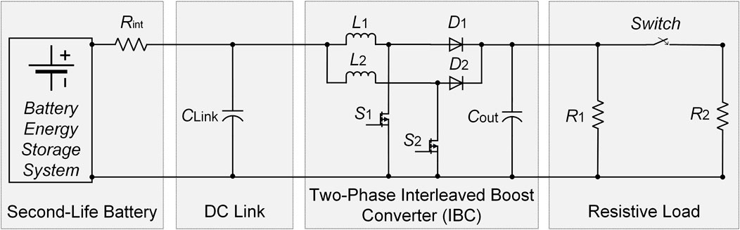
Figure 1. The one-line diagram of the system under investigation.

Even though the SLB exhibits performance limitations, such as increased internal resistance and capacity fade as a result of aging, it serves as an economical and sustainable energy source. The DC-link capacitor stabilizes the input voltage and smooths voltage ripples. Hence, the reliability of the conversion stage is improved. The two-phase IBC is selected to effectively step up the battery voltage to the required higher DC voltage level, while reducing input current ripple, and boosting overall conversion efficiency compared to conventional single-phase converters. A closed-loop control scheme, described later in this work, is developed to effectively regulate the converter’s output voltage, ensuring stable and consistent power delivery to the resistive load despite the inherent uncertainties associated with SLB performance. This integrated system offers a promising solution for sustainably repurposing aged batteries in grid-connected applications.

2.1 Second-life battery (SLB) modeling

In this work, the SLB is modeled to ensure that the aging-induced has influence on its electrical performance. SLBs exhibit notable degradation in capacity, internal resistance, and voltage behavior as a result of the previous usage in electric vehicles, thermal stress, and electrochemical wear (Du et al., 2021). The SLB is represented using an equivalent circuit model consisting of a voltage source Voc (SOC), internal resistance Rint, and degraded capacity CSLB. The open-circuit voltage (OCV) is a function of the state of charge (SOC), represented by a flattened curve due to aging as in Equation 1,

VocSOC=a·SOC+b(1)

where a and b are empirical coefficients derived from aged battery characterization data.

The increased Rint (typically 0.10–0.30 Ω) causes voltage drop under load that is given by Equation 2,

Vterm=VocIin·Rint(2)

The CSLB is modeled as in Equation 3,

CSLB=Cfresh1D(3)

where D is the degradation factor (typically 30–50% capacity loss).

Now, the SOC is calculated using Coulomb counting using Equation 4,

SOCt=SOCt01CSLBt0tItdt(4)

To account for the performance degradation, the SLB parameters were adapted based on empirical and literature-supported degradation trends, as summarized in Table 1. This model enables the accurate simulation of aged battery dynamics in energy storage systems, particularly in applications involving renewable integration or converter-based grid interfacing. It also provides the foundation for evaluating system-level performance under realistic operating conditions using degraded battery assets.

Table 1
www.frontiersin.org

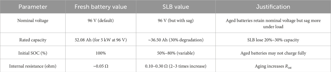
Table 1. Comparative parameters of fresh battery and SLB used in the paper.

2.2 Two-phase interleaved boost converter (IBC) modeling

The simplified state-space model of the two-phase IBC is derived by considering averaged converter small signal approach where the two parallel converter legs are assumed to operate identically but with a 180° phase shift. This interleaving technique improves performance by reducing input and output current ripples and distributing thermal and electrical stress across the switching elements. As illustrated in Figure 1, each phase of the 2-phase IBC comprises an inductor, i.e., L1 and L2, a diode, i.e., D1 and D2, and a controlled power switch, i.e., S1 and S2. Both phases of the two-phase IBC feed into a common output capacitor, i.e., Cout which is connected to a resistive load. By summing the currents of both phases, the system can be represented using an equivalent inductance L, and the total output is connected to a common output capacitor Cout and a resistive load. The model is developed assuming continuous conduction mode (CCM) and ideal components, assuming that the switching ripples and parasitic do not exist. In this case, two state variables are defined, which are the output capacitor voltage, i.e., vout, and the average inductor current, i.e., iL. Assuming ideal components, equal current sharing, and perfectly synchronized operation, the converter can be modeled as a single equivalent boost converter with reduced inductor ripple and effective inductance L/N, where N = 2 for the two-phase case. The state-space equations of the two-phase IBC developed by analyzing energy storage elements during switching intervals (Zhu et al., 2023; Dai et al., 2023).

Assuming ideal and symmetrical operation, the inductor currents share equally, and the total inductor current is defined as in Equation 5,

iLt=iL1t+iL2t(5)

Using the ripple-averaged approach, the dynamic behavior of the converter is described by Equations 6, 7,

Coutdvouttdt=1d·iLtvouttRload(6)
LNdiLtdt=vint1d·voutt(7)

where vout(t) is the output voltage, vin(t) is the input voltage, d is the duty cycle, and N = 2 is the number of interleaved phases.

For small-signal modeling, the equations are linearized around a steady-state operating point as demonstrated in Equations 810,

voutt=Vout+v^outt(8)
iLt=IL+i^Lt(9)
vint=Vin+v^int(10)

Assuming d is constant during the perturbation analysis and only the input voltage vin(t) is subject to disturbance, the linearized equations, i.e., Equations 11, 12 become,

Coutdv^outtdt=1D·i^Ltv^outtRload(11)
LNdi^Ltdt=v^int1D·v^outt(12)

To simplify the model, D is assumed to be small, such that (1 – D) ≈ 1, which yields Equations 13, 14,

Coutdv^outtdt=i^Ltv^outtRload(13)
LNdi^Ltdt=v^intv^outt(14)

Now, let the state vector and input, i.e., Equation 15, be defined as,

x˙t=v^outtl^Lt,u˙t=v^int,y˙t=v^outt(15)

Finally, the system can be expressed in the standard state-space form as presented in Equation 16,

x·t=Axt+But,yt=Cxt+Dut(16)

with the system matrices given by Equation 17,

A=1RLoadCout1CoutNL0,B=0NL,C=10,D=0(17)

where the state vector is, xt=vouttiLtT the control input is the duty cycle d(t), and the measured output is the output voltage y(t).

This model captures the essential dynamics needed for controller design while preserving simplicity for implementation.

3 H-infinity (H) control method for the two-phase interleaved boost converter (IBC)

In power electronics applications, H control has emerged as a powerful solution for regulating converters and inverters under varying load conditions, nonlinearities, and parameter drift. It offers significant advantages over conventional control methods by providing guaranteed stability margins and superior disturbance rejection, making it suitable for high-performance energy systems such as grid-connected converters, renewable energy interfaces, electric drives, etc. Its ability to handle uncertainties makes H control ideal for modern, dynamic power electronic environment. Hence, in this work, to ensure robust output voltage regulation of the two-phase IBC under model uncertainties, load disturbances, and the aging-induced nonidealities of SLBs, an H controller is developed for the simplified model of a two-phase IBC system. The controller is synthesized based on the linearized small-signal averaged model of the converter, derived around a nominal operating point as described in section 2.2 of this paper.

H control is a robust control technique designed to achieve optimal performance and stability in systems subject to model uncertainties and external disturbances. The core idea of H control is to minimize the worst-case gain (in the H norm) from disturbances to the controlled output, ensuring robust performance even when exact system parameters are not fully known, which makes it particularly valuable in applications where reliability and precision are critical.

Figure 2 presents the feedback structure of the weighted H control framework for the two-phase IBC system. The input vector W^=vout,iLT represents the output voltage and inductor current, while the measured plant output is y=vout, is used for feedback. Ps represents the two-phase IBC model, while Cs denotes the H controller to be synthesized. The controller generates the duty cycle d, which is applied to control the converter’s power switches. The weighting functions W1s,W2s and W3s, represented by Ws in Figure 2, are stable transfer functions introduced to shape the error signal, limit the control effort, and enforce robustness against uncertainties, respectively. The performance output is defined as z=Wsy. The closed-loop transfer function from W^ to z characterizes the performance of the H design. The controller output, expressed by d, corresponds to the duty cycle applied to the converter switches. The performance output vector z=z1,z2,z3T includes the weighted signals that capture tracking accuracy, control activity, and disturbance rejection. The closed-loop transfer function from W^ to z, denoted as TZWs characterizes the overall system performance under the H design framework.

Figure 2
Diagram of a control system labeled

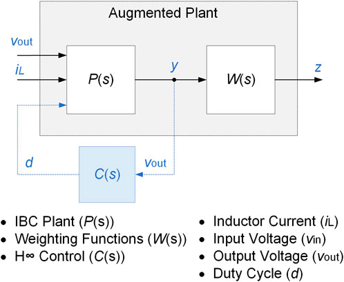
Figure 2. The feedback structure of the weighted H control framework.

The goal of mixed-sensitivity H control is to synthesize a stabilizing controller Ks that minimizes TZWs thereby guaranteeing good tracking performance, bounded control effort, and robustness to disturbances and model uncertainties. The weighting functions specify the desired trade-offs across frequency ranges such as improved tracking and disturbance attenuation at low frequencies can be achieved at the cost of reduced attenuation at higher frequencies, or vice versa. By appropriately designing these weighting functions, the closed-loop system balances tracking performance, control effort limitations, and robustness to uncertainties. It should be emphasized that the generalized augmented plant, which combines the physical converter model with the weighting functions, serves only as a mathematical construct for controller synthesis. Hence, the physical realization of this augmented system is not required. To achieve the goal of mixed-sensitivity H control, the sensitivity functions Ss, the complementary sensitivity function Ts, and the control sensitivity function KsSs, respectively, are defined as in Equations 1820,

Ss=I+GsKs1(18)
Ts=ISs(19)
KsSs=Ks1+GsKs(20)

While Ss describes how well the output follows the reference signal, Ts represents how much the output is affected by measurement noise and model uncertainty. Additionally, KsSs governs the control input effort, to prevent actuator saturation and reduces switching losses. Generally, a low value of Ss and Ts implies better tracking and disturbance rejection, and reduced noise amplification at high frequencies, respectively. Generally, the control problem is to minimize the maximum (peak) gain of these three weighted transfer functions using the following H norm, i.e. Equation 21,

minKsγW1sSsW2sKsSsW3sTs<γ(21)

where γ represents the worst-case closed-loop performance, i.e., performance bound, over all frequencies.

The three weighting functions W1s,W2s and W3s shape the desired performance in the frequency domain. To design an H controller, appropriate selection of weighting functions is critical, as they shape the closed-loop system’s frequency response to meet performance and robustness specifications. The selection of W1s,W2s and W3s was guided by the converter dynamics and the desired closed-loop performance. Hence, W1s,W2s and W3s are employed to respectively enforce tracking performance, limit control effort, and enhance disturbance rejection. These weights are tuned based on the desired bandwidth, settling time, and robustness margins, and can be iteratively refined through frequency-domain analysis or time-domain simulations. For the system investigated in this paper, the target bandwidth was selected considering the dominant time constant of the 2-phase IBC, which is approximately 3.75 ms for the system’s parameters. This time constant leads to a closed-loop bandwidth of about 50 rad/s. Below this frequency, the sensitivity function should be small enough to ensure good reference tracking and strong disturbance rejection, whereas above this frequency, the robustness against noise and unmodeled dynamics is the priority. Hence, W1s, expressed in Equation 22, was shaped to enforce high loop gain at low frequencies, thereby tightening tracking and disturbance rejection.

W1s=30s+150s+0.05(22)

The second weighting function, W2s, was selected as in Equation 23 to reduce the excessive duty-ratio variations and limit control effort, which reduces switching stress.

W2s=s+15s+0.1(23)

Finally, W3s, expressed in Equation 24, was designed to attenuate the complementary sensitivity function at higher frequencies, ensuring robustness to parameter uncertainties.

W3s=7s+3s+35(24)

These design objectives were verified in the frequency domain by overlaying the closed-loop transfer functions S,KS and T with the inverse weights W11,W21 and W31 to respect the condition defined in (Zhang et al., 2023b). While the mixed-sensitivity optimization does not require the closed-loop responses to strictly remain below their corresponding bounds at all frequencies, the overlays demonstrated that the chosen weights yield the intended trade-offs, which are 1) accurate low-frequency tracking, 2) bounded control effort, and 3) improved high-frequency robustness. This process ensures that the presented weight selection is reproducible and that the reported performance improvements can be directly attributed to these design choices.

Figure 3 demonstrates the closed-loop control system structure used for the H synthesis, whereas Table 2 lists the investigated system parameters. The 2-phase IBC is modeled as the nominal plant G(s), with the duty-ratio perturbation as input and the output voltage as the controlled variable. The control objective is to regulate the converter output voltage to track the reference signal Vref(t) in the presence of load changes, input-voltage variations, and unmodeled dynamics. The H controller K(s) is synthesized by shaping the three sensitivity channels, which are the sensitivity function S(s), the control sensitivity function K(s)S(s), and the complementary sensitivity function T(s) through the weighting functions W1s,W2s and W3s, respectively. The resulting closed-loop system guarantees a balanced trade-off among these objectives, with robustness against parameter uncertainty while maintaining stable and fast output voltage regulation.

Figure 3
Schematic of a battery energy storage system with a second-life battery connected to a DC link. It includes a two-phase interleaved boost converter with inductors \(L_1\) and \(L_2\), diodes \(D_1\) and \(D_2\), capacitors \(C_{\text{Link}}\) and \(C_{\text{out}}\), and switches \(S_1\) and \(S_2\). The output is directed to a resistive load with resistors \(R_1\) and \(R_2\) and incorporates a switch. A control system with a controller and PWM generates gate signals.

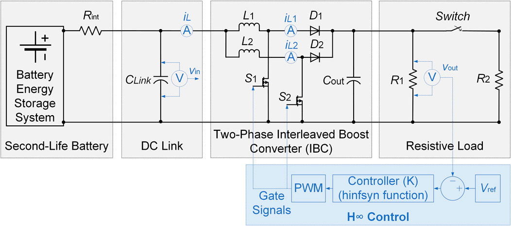
Figure 3. The control block diagram of the proposed H control for two-phase IBC.

Table 2
www.frontiersin.org

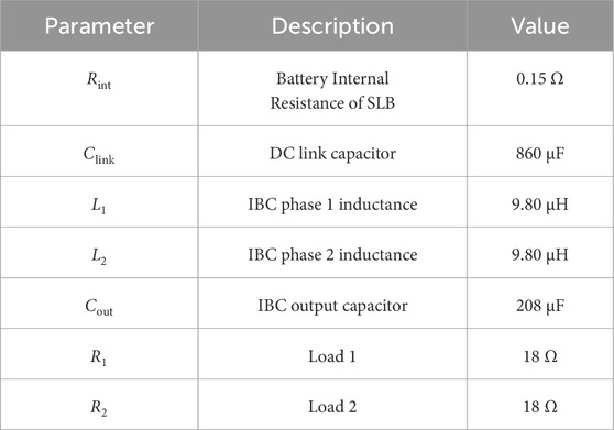
Table 2. Investigated System’s parameters.

Finally, MATLAB’s augw function was used to construct the augmented plant, and MATLAB’s hinfsyn function to solve the problem yields the optimal continuous-time controller Ks with performance level γ. The resulting Ks is directly implemented in Simulink through the LTI System block, ensuring exact realization of the designed continuous-time compensator.

4 Simulation results and discussions

To assess the performance of the proposed H control strategy, a comparative analysis was conducted against a conventional PI controller under identical conditions, including steady-state conditions, load step change, and parameter sensitivity (±30% inductor value change and ±30% capacitor value change). A summary of the comparisons between the classical PI control and the adopted H control is listed in Table 3.

Table 3
www.frontiersin.org

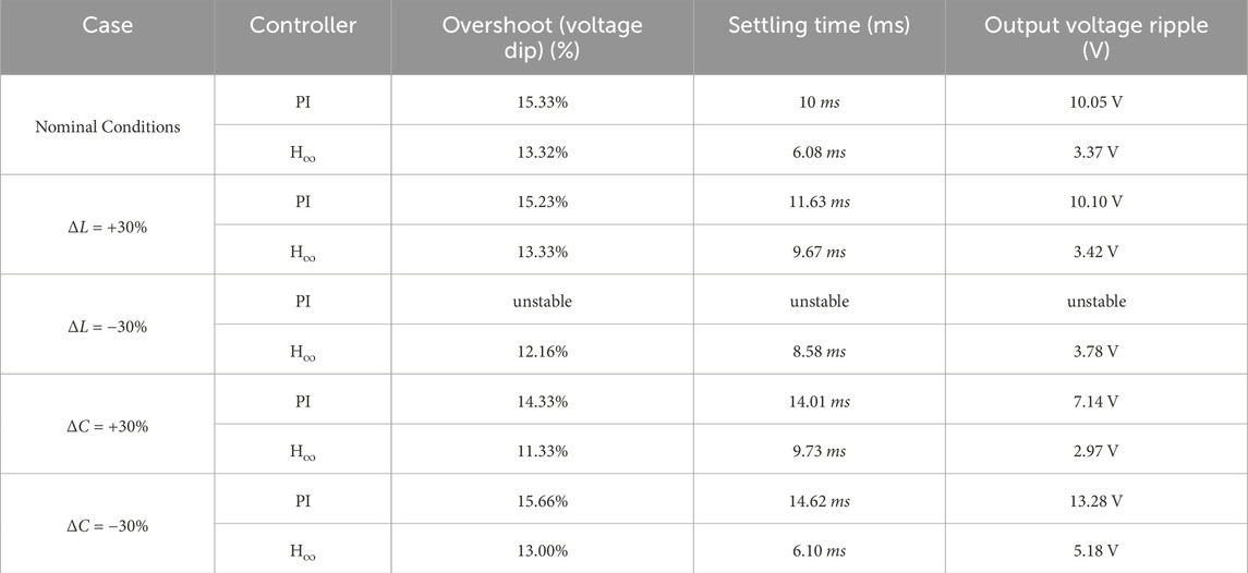
Table 3. Quantitative comparison of PI and H controllers under nominal conditions and parameter variations.

4.1 Comparative performance evaluation for H control and PI control during a load step change

During the load step change, the H controller demonstrates superior voltage regulation performance as presented in Figure 4. Prior to the disturbance at t = 0.15 s, the output voltage, vout, precisely tracks the voltage reference, Vref, and following the load step, the controller smoothly corrects the voltage dip with minimal overshoot, i.e. 13.32%, a fast-settling time around 6 ms, and only 3.5 V output ripple. In contrast, the PI controller, presented in Figure 5, shows a more voltage sag, i.e. 15.33%, after the load step, a slower recovery time, around 10 ms, and larger output ripple, i.e. 9.30 V. This means that the output voltage under PI control also exhibits increased ripple and less damping, indicating weaker transient performance. Additionally, the input voltage drawn from the SLB drops at the instant of the load change for both control strategies. However, the system controlled by H controller shows less voltage sag and a faster recovery, implying more efficient energy transfer as illustrated in Figure 4. The PI-controlled system, presented in Figure 5, shows a deeper and longer-lasting dip, which could negatively impact battery stress and system stability. As demonstrated in Figures 4, 5, both controllers show a significant rise in output current following the load increase. However, the H controller achieves this transition more smoothly, with better damping and no excessive peaking. The PI-controlled system, on the other hand, exhibits a sharper current transient and slower stabilization. This suggests that the PI controller is more sensitive to sudden load changes. The output power under H control increases cleanly and proportionally in response to the load step in, reaching a new steady-state of only 6.08 ms with minimal oscillation. In contrast, the PI controller produces a more oscillatory power transition, with a slightly delayed convergence. The system required around 10 ms to reach its reference. This illustrates the superior dynamic power handling capability of the H controller, as it can achieve more than 40% faster dynamic response and more than 50% output ripple improvement considering the system investigated in this work.

Figure 4
Four graphs display electrical data over time. (a) Two-phase IBC output voltage fluctuating between 290V to 320V, with a disturbance lasting 6.08 milliseconds.(b) Output current starting at 16.60A, rising to 33.20A.(c) SLB voltage dropping from 87.50V to 73V.(d) IBC output power increasing from 5 kilowatts to 10 kilowatts. Each graph covers a time span from 0.12 to 0.18 seconds.

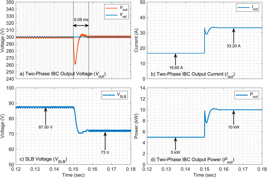
Figure 4. Two-phase IBC results during load step change using H controller.

Figure 5
Four-panel chart showing electrical parameters of a two-phase interleaved boost converter (IBC). Panel a: Plot of output voltage Vout decreasing sharply at 15 second, then stabilizing near 310 volts. Panel b: Output current (I_{out}) rises from 16.60 amps to 33.20 amps. Panel c: Second-life battery voltage (SLB) voltage (V_{SLB}) drops from 87 volts to 68 volts. Panel d: Output power (P_{out}) increases from 5 kilowatts to 10 kilowatts. All graphs are against time, ranging from 0.12 to 0.18 seconds.

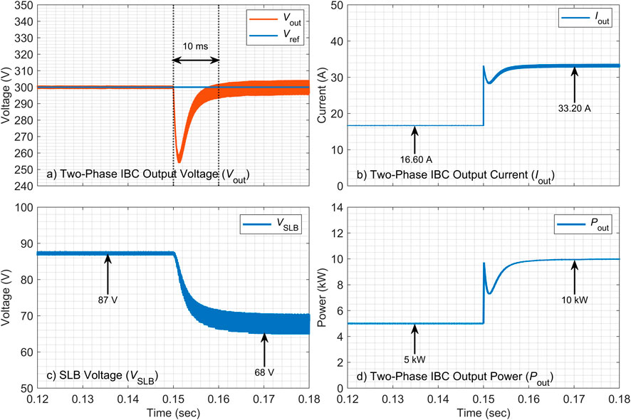
Figure 5. Two-phase IBC results during load step change using PI controller.

4.2 Comparative performance evaluation for H control and PI control during parameter sensitivity tests

In this section of this paper, several parameter sensitivity tests have been performed to evaluate the robustness of the H controller over the classical PI control. These tests include the ±30% change in the inductors’ and capacitor’s values of the IBC.

4.2.1 + 30% inductor value change

Based on the results presented in Figure 6 of the parameter sensitivity test, a clear performance advantage of the H control over the conventional PI control is demonstrated when the inductor value is increased by 30%. The H controller maintains excellent regulation of the converter output voltage despite the parametric variation, with a tightly bounded deviation from the reference voltage, Vref. The maximum observed voltage spike of approximately 3.37 V during steady-state conditions after the load step change. The SLB voltage, i.e., VSLB, also exhibits a stable and smooth discharge profile. In contrast, the PI controller, depicted in Figure 7, shows significantly degraded performance under similar conditions. The output voltage displays substantial dip and sustained oscillations. Furthermore, the source voltage from the SLB exhibits fluctuations, indicating higher stress and a less stable operation. This comparative analysis clearly shows that the proposed H control strategy possesses superior robustness, maintaining system stability and performance integrity during parameter uncertainties, whereas the PI controller is susceptible to performance degradation.

Figure 6
Two graphs show voltage over time from 0.1 to 0.2 seconds. Graph (a) displays an orange line representing Two-Phase IBC output voltage with small fluctuations around 300V with small fluctuations around 300V i.e., 3.78V and 3.37V, before and after the load transient repectively. Graph (b) shows SLB voltage in blue, fluctuating near 87.50V with a notable drop to 73V. Each graph includes labeled points and lines.

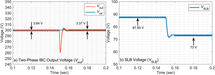
Figure 6. Two-phase IBC output voltage and SLB voltage during H control with ∆L = +30%.

Figure 7
Two graphs demonstrate voltage changes over time. The left graph shows the two-phase IBC output voltage decreasing from 300V to approximately 255 V at t = 0.15 second before stabilizing near 300 volts. The right graph shows SLB voltage decreasing from 87.40 to 70 volts between 0.13 and 0.18 seconds.

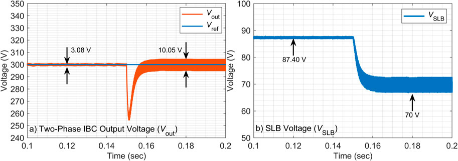
Figure 7. Two-phase IBC output voltage and SLB voltage during PI control with ∆L = +30%.

4.2.2 −30% inductor value change

The robustness of the H control is further validated when the inductor value is decreased by 30%, as illustrated in Figure 8. Under this parametric deviation, the H controller, presented in Figure 8, continues to demonstrate better performance, effectively regulating the output voltage with a deviation of approximately 3.78 V. While VSLB shows a more dynamic response with a significant dip to 68.9 V, it recovers stably, indicating the controller’s ability to manage larger transients. In contrast, the PI controller, demonstrated in Figure 9, fails to maintain stable operation. The output voltage exhibits severe and growing oscillations, signifying a loss of regulatory control, which has led to system instability. The source voltage also displays large-signal instability. Hence, this test shows that PI control exhibits a critical weakness when faced with reduced inductance, whilst considering the exact same conditions, the developed H controller shows robustness to model uncertainty proves to be a decisive advantage, ensuring continued and stable converter operation.

Figure 8
Graph 1 shows the two-phase IBC output voltage (V_{out}) fluctuating around 300 volts,with voltage ripple around 3.13V and 3.78V, respectively, at specific points. Graph 2 displays the SLB voltage (V_{SLB}), starting at 87.20 volts and dropping to 68.90 volts at about 0.13 seconds. Both graphs plot voltage against time in seconds.

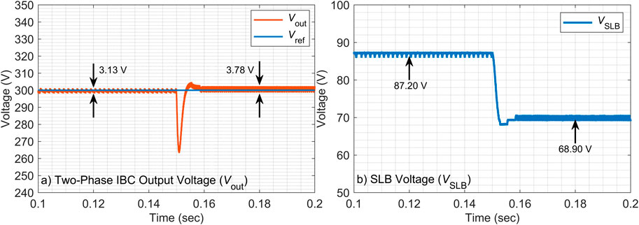
Figure 8. Two-phase IBC output voltage and SLB voltage during H control with ∆L = −30%.

Figure 9
Two graphs depicting voltage data over time. The left graph shows two-phase interleaved boost converter output voltage marked as (V_{out}) in red and reference voltage (V_{ref}) in blue. Both voltages are stable near 300V before they become unstable after the load was increased at t = 0.15 second. The right graph displays second-life battery VSLB that is stable from 0.1 second to 0.15 second, then becoming unstable after 0.15 second. Both graphs indicate instability at similar time points.

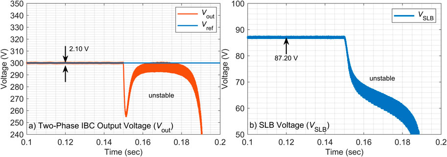
Figure 9. Two-phase IBC output voltage and SLB voltage during PI control with ∆L = −30%.

4.2.3 + 30% capacitor value change

To further evaluate the effectiveness of H controller, the performance evaluation was extended to a 30% increase in the output capacitor value, with the results presented in Figures 10, 11. The H controller successfully handles this parametric change, maintaining robust output voltage regulation with a transient deviation of approximately 2.97 V as illustrated in Figure 10. The SLB voltage, VSLB, exhibits a controlled transient dip to 72 V, demonstrating a stable and well-damped system response. In contrast, Figure 11 shows that the PI controller has obtained a significantly degraded and oscillatory response during the same test. The output voltage is characterized by a large overshoot of 7.14 V, followed by persistent oscillations, indicating poor stability margins and ineffective damping. This oscillatory behavior is also reflected in the source voltage, which shows associated fluctuations. This comparison highlights the superior ability of the H control to maintain stability and performance despite increased capacitance, a change that critically undermines the performance of the conventional PI controller.

Figure 10
Graph illustrating two voltage plots over time, with two panels labeled a and b. Panel a shows the two-phase IBC output voltage (Vout) in orange, with voltage ripple i.e., 2.97V before t=0.15s and voltage ripple i.e., 2.85V after the transient. Panel b displays SLB voltage (VSLB) in blue, decreasing from 87.50 volts to 72 volts.

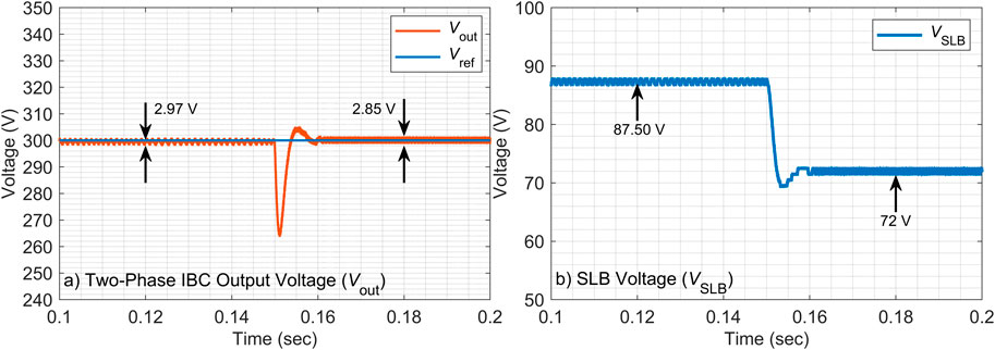
Figure 10. Two-phase IBC output voltage and SLB voltage during H control with ∆C = +30%.

Figure 11
Graph illustrating voltage over time for a two-phase IBC output and SLB voltage. Panel a shows Vout (red) and Vref (blue) with voltage fluctuations i.e., 1.72V and 7.14V, respectively.. Panel b displays V_{SLB} (blue) with a drop from 87.30 volts to 68 volts, stabilizing thereafter. Both graphs cover the time range from 0.1 to 0.2 seconds.

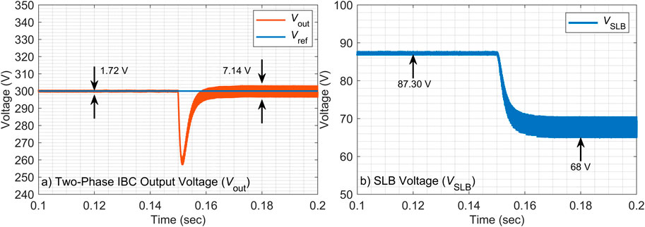
Figure 11. Two-phase IBC output voltage and SLB voltage during PI control with ∆C = +30%.

4.2.4 −30% capacitor value change

The final parameter sensitivity test involved a 30% reduction in the output capacitor value, with the results compared in Figures 12, 13. The H controller, shown in Figure 12 once again demonstrates its resilience, effectively regulating the output voltage with a defined but controlled transient spike of 5.18 V. The SLB voltage, i.e., VSLB, shows a predictable and stable transient response. Contrary, Figure 13 shows that the PI controller exhibits critically unstable behavior under these conditions with significant oscillations. The output voltage response is characterized by a large overshoot of 13.28 V and sustained oscillations. This is accompanied by correlating disturbances in the source voltage. This indicates that the reduced system inertia caused by lower capacitance severely challenges the fixed-gain PI controller, while the H controller’s robust design maintains closed-loop stability and acceptable performance, conclusively proving its superiority in managing parametric uncertainties.

Figure 12
Two graphs display voltage changes over time. The first graph shows Two-Phase IBC Output Voltage Vout 255V, then stablizing around 300V with voltage fluctuation, i.e., 7.14V. The second graph shows SLB Voltage (V_{SLB}) decreasing from 87.50 volts to 72 volts. A legend indicates lines representing (V_{out}), ( V_{ref}), and (V_{SLB}).

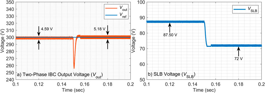
Figure 12. Two-phase IBC output voltage and SLB voltage during H control with ∆C = −30%.

Figure 13
Graph a) displays the Two-Phase IBC output voltage (V_{out}) in orange and reference voltage (V_{ref}) in blue, showing a dip from 300V to below 250V at t=0.15 second. Graph b) illustrates SLB voltage (V_{SLB}) in blue, depicting a decrease from 87 V to 68 V within the same time frame. Both graphs plot voltage (V) against time (seconds).

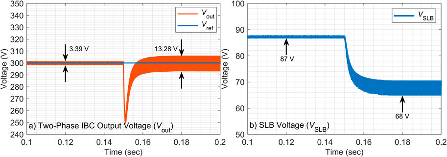
Figure 13. Two-phase IBC output voltage and SLB voltage during PI control with ∆C = −30%.

4.3 Discussions

Under nominal operating conditions, the H controller achieved a lower overshoot, i.e. 13.32% a significantly shorter settling time, i.e. 6.08 ms, and a reduced output ripple, i.e. 3.37 V. One the other hand, when the PI controller was applied, a higher overshoot, i.e. 15.33%, a longer the settling time, i.e. 10 ms and a larger output ripple, i.e. 10.05 V, were observed. For a +30% inductor variation, the H controller maintained robust performance with overshoot of 13.33% and settling time of 9.67 ms, whereas the PI controller exhibited larger overshoot, i.e. 15.23%, and longer settling time, i.e. 11.63 ms. Under a −30% inductor variation, the PI controller was unstable, while the H controller remained stable with overshoot of 12.16%, settling time of 8.58 ms, and output ripple of only 3.78 V, demonstrating clear robustness to parameter uncertainty. Similarly, with a +30% capacitor change, the H controller outperformed the PI control by achieving overshoot of 11.33%, settling time of 9.73 ms, and output ripple of 2.97 V. In contrast, the PI control showed overshoot of 14.33%, settling time of 14.01 ms, and output ripple of 7.14 V, considering the exact same +30% capacitor change. For a −30% capacitor variation, the PI controller showed degraded performance, i.e. 15.66% overshoot, 14.62 ms settling time, and 13.28 V output ripple, whereas the H controller improved both dynamic and steady-state behavior by accomplishing a 13.00% overshoot, 6.10 ms settling time, and a 5.18 V output ripple.

Overall, these quantitative comparisons, listed in Table 3, confirm that the proposed H control strategy consistently outperforms the conventional PI control in terms of transient response and robustness. On average, the H controller reduces overshoot by around 15%, settling time by about 40%, and output ripple by more than 50% across all tested conditions. These results provide strong evidence for the suitability of H control in SLB-based interleaved boost converters where parameter variations and uncertainties are common.

5 Conclusion

This research successfully developed and validated a robust H control strategy for an IBC interfacing SLBs. The proposed controller was specifically designed to address the critical challenges of system uncertainties and performance variations inherent in SLB applications. Extensive simulation analyses under severe parameter variations of ±30% in both inductance and capacitance demonstrated the superior performance of the H controller over a conventional PI controller. The key findings show that the H control achieved robust voltage regulation with minimal overshoot and eliminated instability, while the PI control failed under the same conditions, exhibiting severe oscillations and voltage spikes. Furthermore, the proposed scheme provided a 40% faster dynamic response and significantly reduced output ripple, i.e., more than 50% on average. These results robustly validate the H controller as a highly effective and resilient solution for ensuring the stability, efficiency, and reliability of SLB integration into modern energy storage systems.

Data availability statement

The original contributions presented in the study are included in the article/supplementary material, further inquiries can be directed to the corresponding author.

Author contributions

WA: Conceptualization, Formal Analysis, Investigation, Methodology, Project administration, Software, Supervision, Validation, Visualization, Writing – original draft, Writing – review and editing. OA: Conceptualization, Funding acquisition, Methodology, Project administration, Supervision, Validation, Visualization, Writing – original draft, Writing – review and editing. SB: Conceptualization, Formal Analysis, Investigation, Methodology, Software, Validation, Visualization, Writing – review and editing.

Funding

The author(s) declare that financial support was received for the research and/or publication of this article. The authors extend their appreciation to Prince Sattam bin Abdulaziz University for funding this research work through the project number (PSAU/2023/01/27070).

Conflict of interest

The authors declare that the research was conducted in the absence of any commercial or financial relationships that could be construed as a potential conflict of interest.

Generative AI statement

The author(s) declare that Generative AI was used in the creation of this manuscript. To improve and review English writing.

Any alternative text (alt text) provided alongside figures in this article has been generated by Frontiers with the support of artificial intelligence and reasonable efforts have been made to ensure accuracy, including review by the authors wherever possible. If you identify any issues, please contact us.

Publisher’s note

All claims expressed in this article are solely those of the authors and do not necessarily represent those of their affiliated organizations, or those of the publisher, the editors and the reviewers. Any product that may be evaluated in this article, or claim that may be made by its manufacturer, is not guaranteed or endorsed by the publisher.

References

Ait, R. N., Rahoui, A., Boukais, B., Benkhoris, M. F., Ait-Ahmed, M., and Djerioui, A. (2024). Design and implementation of robust H control for improving disturbance rejection of grid-connected three-phase PWM rectifiers. Energies 17 (9), 2166. doi:10.3390/en17092166

CrossRef Full Text | Google Scholar

Boukerdja, M., Chouder, A., Hassaine, L., Bouamama, B. O., Issa, W., and Louassaa, K. (2020). H Based control of a DC/DC buck converter feeding a constant power load in uncertain DC microgrid system. ISA Trans. 105, 278–295. doi:10.1016/j.isatra.2020.05.031

PubMed Abstract | CrossRef Full Text | Google Scholar

Dai, Z., Liu, J., Li, K., Mai, Z., and Xue, G. (2023). Research on a modeling and control strategy for interleaved boost converters with coupled inductors. Energies 16, 3810. doi:10.3390/en16093810

CrossRef Full Text | Google Scholar

Dipti, K., Siddharth, S., Renata, A., Hyung, C. K., and Annick, A. (2020). Evaluating the cost and carbon footprint of second-life electric vehicle batteries in residential and utility-level applications. Waste Manag. 113, 497–507. doi:10.1016/j.wasman.2020.05.034

PubMed Abstract | CrossRef Full Text | Google Scholar

Du, B., Yu, Z., Yi, S., He, Y., and Luo, Y. (2021). State-of-charge estimation for second-life lithium-ion batteries based on cell difference model and adaptive fading unscented Kalman filter algorithm. Int. J. Low-Carbon Technol. 16 (3), 927–939. doi:10.1093/ijlct/ctab019

CrossRef Full Text | Google Scholar

Fazeli, A., Stadie, M., Kerner, M., Poplavskaya, K., Nagaoka, H., Kapeller, J., et al. (2021). “A techno-economic investigation for the application of second-life electric vehicle batteries for behind-the-meter services,” in Proc. IEEE Elect. Power Energy Conf., 20–27. doi:10.1109/EPEC52095.2021.9621638

CrossRef Full Text | Google Scholar

Gokul, S. T., Mehdi, S., Elmira, J., Ben, H., Saad, M., and Alex, S. (2022). Role of optimization techniques in microgrid energy management systems—A review. Energy Strategy Rev. 43, 100899. doi:10.1016/j.esr.2022.100899

CrossRef Full Text | Google Scholar

Gorji, S. A., Sahebi, H. G., Ektesabi, M., and Rad, A. B. (2019). Topologies and control schemes of bidirectional DC–DC power converters: an overview. IEEE Access 7, 117997–118019. doi:10.1109/ACCESS.2019.2937239

CrossRef Full Text | Google Scholar

Hameed, H. Q., Hasan, F. A., and Rashad, L. J. (2025). Robust H control for master-slave power converters in renewable energy systems. Adv. Electr. Eng. Electron. Energy 13, 101104. doi:10.1016/j.prime.2025.101104

CrossRef Full Text | Google Scholar

Haram, M. H. S. M., Sarker, M. T., Ramasamy, G., and Ngu, E. E. (2023). Second life EV batteries: technical evaluation, design framework, and case analysis. IEEE Access 11, 138799–138812. doi:10.1109/ACCESS.2023.3340044

CrossRef Full Text | Google Scholar

Hassanpour, N., Chub, A., Yadav, N., Blinov, A., and Vinnikov, D. (2024). High-efficiency partial power converter for integration of second-life battery energy storage systems in DC microgrids. IEEE Open J. Ind. Electron. Soc. 5, 847–860. doi:10.1109/OJIES.2024.3389466

CrossRef Full Text | Google Scholar

He, G., Chen, Q., Moutis, P., Kar, S., and Whitacre, J. F. (2022). An intertemporal decision framework for electrochemical energy storage management. Nat. Energy 7, 404–412. doi:10.1038/s41560-018-0129-9

CrossRef Full Text | Google Scholar

Khan, A. M., Hekmati, A., and Bagheri, M. (2025). Enhancing cost-effectiveness in residential microgrids: an optimization for energy management with proactive electric vehicle charging. Front. Energy Res. 13, 1454448. doi:10.3389/fenrg.2025.1454448

CrossRef Full Text | Google Scholar

Korada, D. M. R., and Mishra, M. K. (2023). Fixed switching frequency model predictive current control for grid-connected inverter with improved dynamic and steady state performance. IEEE Access 11, 104094–104105. doi:10.1109/ACCESS.2023.3317537

CrossRef Full Text | Google Scholar

Lakshmi, S. N. D., and Marimuthu, R. (2025). Distributed model predictive control strategy for microgrid frequency regulation. Energy Rep. 13, 1158–1170. doi:10.1016/j.egyr.2024.12.071

CrossRef Full Text | Google Scholar

Li, Z., Xie, D., Ye, H., Li, Y., Li, J., Chen, Y., et al. (2025). Chance-constrained optimal schedule of battery energy storage considering the uncertainties of renewable generation. Front. Energy Res. 13, 1588704. doi:10.3389/fenrg.2025.1588704

CrossRef Full Text | Google Scholar

Liu, Z., Jouzdani, J. E., and Eren, S. (2025). “Novel H-infinity controller for DAB converter under constant current load,” in IEEE 34th Int. Symp. Ind. Electron. (ISIE) (Toronto, Canada), 1–6. doi:10.1109/ISIE62713.2025.11124786

CrossRef Full Text | Google Scholar

Luo, W., Stynski, S., Chub, A., Franquelo, L. G., Malinowski, M., and Vinnikov, D. (2021). Utility-scale energy storage systems: a comprehensive review of their applications, challenges, and future directions. IEEE Ind. Electron. Mag. 15 (4), 17–27. doi:10.1109/MIE.2020.3026169

CrossRef Full Text | Google Scholar

Mandrile, F., Pastorelli, M., Musumeci, S., Urkiri, I. A., and Remirez, A. (2023). Second life management from battery storage system of electric waterborne transport applications: perspectives and solutions. IEEE Access 11, 35122–35139. doi:10.1109/ACCESS.2023.3265168

CrossRef Full Text | Google Scholar

Mukherjee, N., and Strickland, D. (2015). Control of second-life hybrid battery energy storage system based on modular boost-multilevel buck converter. IEEE Trans. Ind. Electron. 62 (2), 1034–1046. doi:10.1109/TIE.2014.2341598

CrossRef Full Text | Google Scholar

Mukherjee, N., and Strickland, D. (2016). Analysis and comparative study of different converter modes in modular second-life hybrid battery energy storage systems. IEEE J. Emerg. Sel. Top. Power Electron. 4 (2), 547–563. doi:10.1109/JESTPE.2015.2460334

CrossRef Full Text | Google Scholar

Naim, R., Weiss, G., and Ben-Yaakov, S. (1997). Hcontrol applied to boost power converters. IEEE Trans. Power Electron. 12 (4), 677–683. doi:10.1109/63.602563

CrossRef Full Text | Google Scholar

Shan, Y., Hu, J., and Guerrero, J. M. (2020). A model predictive power control method for PV and energy storage systems with voltage support capability. IEEE Trans. Smart Grid 11 (2), 1018–1029. doi:10.1109/TSG.2019.2929751

CrossRef Full Text | Google Scholar

Song, H., Chen, H., Wang, Y., and Sun, X.-E. (2024). An overview about second-life battery utilization for energy storage: key challenges and solutions. Energies 17, 6163. doi:10.3390/en17236163

CrossRef Full Text | Google Scholar

Wang, Y., and He, J. (2022). “Fast solution of adaptive dynamic programming for intelligent vehicle predictive controller,” in China automation congress (CAC) (Xiamen, China), 1918–1923. doi:10.1109/CAC57257.2022.10055132

CrossRef Full Text | Google Scholar

Wu, L., Liu, J., Vazquez, S., and Mazumder, S. K. (2022). Sliding mode control in power converters and drives: a review. IEEE/CAA J. Autom. Sin. 9 (3), 392–406. doi:10.1109/JAS.2021.1004380

CrossRef Full Text | Google Scholar

Yıldıran, N., and Tacer, E. (2019). A new approach to H-infinity control for grid-connected inverters in photovoltaic generation systems. Electr. Power Components Syst. 47, 1413–1422. doi:10.1080/15325008.2019.1689445

CrossRef Full Text | Google Scholar

Zhang, Y., Wei, D., Luo, F., Deng, Y., Qiu, J., and Dong, Z. Y. (2023a). Two-stage capacity determination framework for residential second-life BESSs considering cloud energy storage service. IEEE Syst. J. 17 (3), 4737–4747. doi:10.1109/JSYST.2022.3232732

CrossRef Full Text | Google Scholar

Zhang, X., Zhao, Y., Jiang, H., and Wei, M. (2023b). Design of integral sliding mode control and fuzzy adaptive PI control for voltage stability in DC microgrid. Front. Energy Res. 11, 1278305. doi:10.3389/fenrg.2023.1278305

CrossRef Full Text | Google Scholar

Zhao, Y., Li, H., Wan, C., Du, D., and Chen, B. (2025). Microgrid energy management considering energy storage degradation cost. Batteries 11, 169. doi:10.3390/batteries11050169

CrossRef Full Text | Google Scholar

Zhu, H., Zhang, D., Liu, X., Zhang, M., and Zhang, B. (2023). A family of interleaved boost converters for battery discharging in space applications. IEEE Trans. Power Electron. 38 (2), 1887–1900. doi:10.1109/TPEL.2022.3211837

CrossRef Full Text | Google Scholar

Keywords: interleaved boost converter (IBC), second-life battery (SLB), energy storage system (ESS), grid integration, H-infinity control

Citation: Alhosaini W, Aldosari O and Batiyah S (2025) Robust H-infinity control of a two-phase interleaved boost converter for second-life battery integration in battery energy storage systems. Front. Energy Res. 13:1689813. doi: 10.3389/fenrg.2025.1689813

Received: 20 August 2025; Accepted: 30 September 2025;
Published: 10 November 2025.

Edited by:

Shuang Zhao, Hefei University of Technology, China

Reviewed by:

Mahmood Saadeh, The Hashemite University, Jordan
Med Darwish, Brunel University London, United Kingdom

Copyright © 2025 Alhosaini, Aldosari and Batiyah. This is an open-access article distributed under the terms of the Creative Commons Attribution License (CC BY). The use, distribution or reproduction in other forums is permitted, provided the original author(s) and the copyright owner(s) are credited and that the original publication in this journal is cited, in accordance with accepted academic practice. No use, distribution or reproduction is permitted which does not comply with these terms.

*Correspondence: Obaid Aldosari, b20uYWxkb3NhcmlAcHNhdS5lZHUuc2E=

Disclaimer: All claims expressed in this article are solely those of the authors and do not necessarily represent those of their affiliated organizations, or those of the publisher, the editors and the reviewers. Any product that may be evaluated in this article or claim that may be made by its manufacturer is not guaranteed or endorsed by the publisher.