 Ibrahim Altarjami
- Department of Electrical Engineering, Taibah University, Medina, Saudi Arabia
With the shift toward renewable-dominant power systems, concerns about small-signal stability have intensified, driven by reduced inertia and the loss of inherent damping formerly provided by synchronous machines. These challenges are amplified in aggregated networks and clustered photovoltaic (PV) installations, where the likelihood of poorly damped oscillatory modes increases especially in weak grids. Inverter-based energy storage can mitigate these issues, but its effectiveness depends critically on the control paradigm. This paper compares grid-following (GFL) and grid-forming (GFM) energy storage for mitigating small-signal instability in renewable-rich grids with clustered PV. A dynamic test system with high PV penetration is modeled, and its oscillatory behavior is assessed using eigenvalue and modal analyses. The study evaluates two configurations, GFL-integrated storage and GFM-integrated storage across varying penetration levels and grid strengths. Both approaches enhance stability, but GFM consistently achieves superior damping, with eigenvalues shifting deeper into the stable region. GFL provides moderate improvement yet remains vulnerable under weak-grid (low short-circuit strength) conditions due to phase-locked loop dynamics. Overall, GFM is more effective at suppressing oscillatory interactions, particularly in clustered PV settings. While GFL integration is simpler and broadly applicable, its stability-enhancement potential is weaker in renewable-intensive systems. These findings offer practical guidance for system operators and planners.
1 Introduction
Modern power systems are rapidly transitioning from synchronous generation to inverter-based resources (IBRs), a structural change that lowers inertia and short-circuit strength and thereby reshapes the physics and taxonomy of stability (Singh et al., 2024). Small-signal stability is particularly exposed because the inertial and damping properties that synchronous machines once provided intrinsically are not guaranteed by generic inverter controls, especially under weak-grid conditions (Rudnik et al., 2022). This vulnerability is amplified when photovoltaic (PV) capacity is geographically clustered in resource-rich corridors: concentrated IBR penetration creates pockets of weak strength and a non-uniform spatial distribution of inertia, which localizes mode shapes and elevates poorly damped inter-area oscillations during system upsets (Hu et al., 2019; Njoka et al., 2025). In such settings, the question is not simply whether more IBRs can be accommodated, but how to restore adequate damping when inertia is unevenly distributed across the network.
The literature has documented both the erosion of inertia with rising renewable penetration and the promise of synthetic or “virtual” inertia to mitigate emergent oscillatory behavior (Singh et al., 2024; Rudnik et al., 2022; Mosca et al., 2019; J et al., 2024). Evidence from modified IEEE benchmarks shows notable reductions in synchronization capability and stability margins as IBR shares grow, underscoring why conventional control assumptions fail as grids decarbonize (Njoka et al., 2025). Yet much of this body of work implicitly treats “low inertia” as a uniform, system-wide attribute. In practice, siting realities—irradiance, land availability, corridor access—induce spatially non-uniform strength and inertia. Under clustered PV, inter-area modes tend to anchor around weak, highly inverterized sub-regions; consequently, the effectiveness of any stabilizing intervention depends not only on how much control capacity is installed, but critically on where that control authority is applied (Hu et al., 2019; Njoka et al., 2025).
Against this backdrop, the inverter control paradigm is pivotal. Most deployed converters remain phase-locked-loop (PLL)–based grid-following (GFL) units that require a strong voltage reference and can interact adversely with network impedance at low short-circuit ratios (SCR) (Mosca et al., 2019). Grid-forming (GFM) inverters instead regulate terminal voltage and frequency, emulate synchronous-machine behavior and contribute synthetic inertia and damping with improved robustness in weak conditions (Mosca et al., 2019; Khan et al., 2022). Case studies consistently indicate that a battery energy storage system (BESS) operated in GFM mode damps oscillations more effectively than the same BESS in GFL mode, with the benefit most pronounced where PLL dynamics are fragile (Hu et al., 2019; J et al., 2024; Zhang et al., 2022). Broader syntheses corroborate GFM advantages across root-locus and eigenvalue shifts, settling and overshoot, classical SISO margins, and resonance robustness, including at very high IBR fractions given appropriate tuning and coordination or mode switching (Mirmohammad and Azad, 2024; Gajare et al., 2025; Han et al., 2024; Liu et al., 2024; Zhang et al., 2022) field-oriented reports link GFM-BESS to suppression of sub-synchronous oscillations and increased hosting capacity (Arraño-Vargas et al., 2023; Yang et al., 2021). What these comparisons often leave unanswered, however, is the capacity question central to planning: how much storage, under which control mode, is minimally required to recover a target damping ratio when inertia is unevenly distributed.
Sizing and placement methodologies begin to address that planning layer. Prior work shows that the storage capacity required for stability generally grows with renewable penetration, while placement guided by oscillatory-mode residues or participation factors delivers outsized damping impact per unit capacity (Assery et al., 2023). Practical heuristics, e.g., proximity to the Center of Inertia (COI) or placing at high-leverage nodes identified by SCR can also be effective, contingent on topology and dominant mode shape. Nonetheless, an integrated, capacity-aware comparison COI-distance under clustered PV, assessed under both GFL and GFM control on a consistent testbed, remains limited. This gap is especially consequential in renewable-majority grids where budget, placing, and operational constraints require targeted, least-capacity interventions rather than blanket deployments.
Motivated by these deficiencies, this paper focuses explicitly on clustered-PV morphology and the resulting uneven inertia distribution, and it advances a comparative, capacity-normalized assessment of GFL-versus GFM-operated storage for small-signal stability restoration. A high-penetration PV test system is modeled, and eigenvalue and modal analyses are used to quantify how control mode, grid strength, and PV penetration shape the critical inter-area oscillation. The study estimates the minimum BESS capacity required to achieve a specified damping target under like-for-like GFL and GFM implementations and examines how placement metrics residue-based damping potential and COI distance mediate those capacity needs (Assery et al., 2023; Mosca et al., 2019; Zhang et al., 2022; Mirmohammad and Azad, 2024; Gajare et al., 2025; Arraño-Vargas et al., 2023; Yang et al., 2021). By holding two factors fixed while varying the third (control versus capacity), the analysis disentangles what truly drives stability improvements and yields planning-oriented indices such as damping-per-MWh that directly inform how much to install, and which control mode offers the best damping return per unit capacity in renewable-dominated grids with clustered PV.
2 System modelling and methodology
2.1 Two-area power system configuration
All simulations were performed in Power System Simulator for Engineering (PSSe) automated by Python, using the Kundur two-area (four-generator) model available from the Illinois Center for a Smarter Electric Grid (ICSEG) at the University of Illinois at Urbana-Champaign. The key change in the analysis is that the penetration of renewable power in Area 1 has increased incrementally, and no change is reflected in the inertia of the loading area (Area 2), as shown in Figure 1. This strategy deliberately makes the generation region weak, leaving the inertia of the system unevenly distributed over the system. One of the objectives is the investigation of the influence of this unbalanced distribution of the inertia on the oscillations of the systems and small signal stability. The study aims to determine the stability boundaries of the system as inertia decreases by increasing renewable penetration within the generation regime, thereby providing insights into how such transformations may impact oscillatory modes and the system’s overall stability.
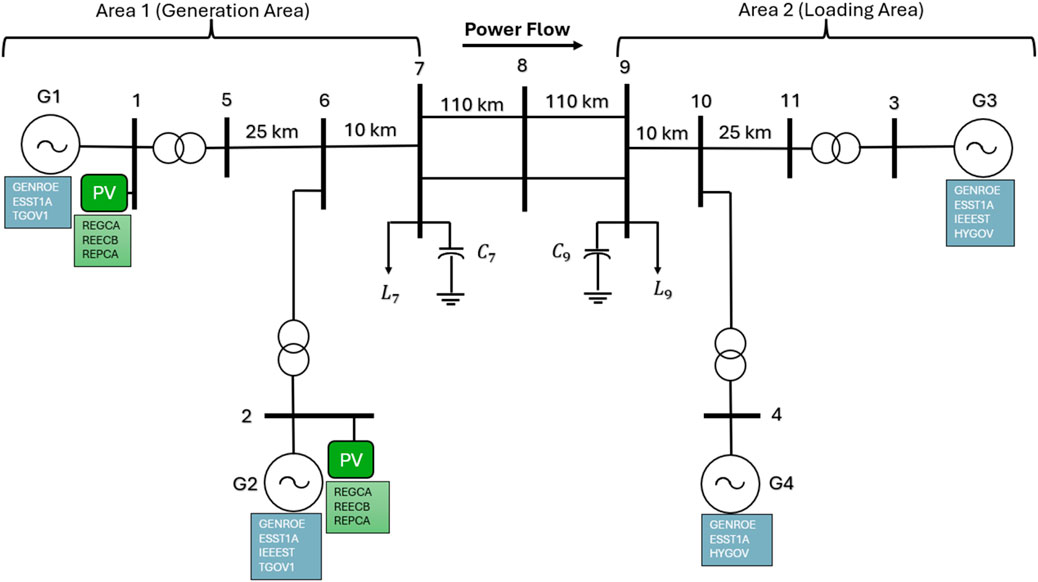
Figure 1. Kundur System model in the study using PSSe.
The main goal of the analysis is to decrease the storage size that must be provided to damp the primary mode of oscillation successfully. The study aims to determine the minimum storage required to maintain system stability by introducing grid-forming and grid-following storage products in the generation region. The analysis also ensures that the variation in the distance of the center of inertia does not increase to an unacceptable extent as renewable penetration grows, thereby affecting trade stability and efficiency.
2.2 Component models in PSSe
2.2.1 Photovoltaic (PV) system modelling
To accurately simulate the dynamic aspect of utility-scale photovoltaic (PV) generation during high-penetration periods, this paper utilizes the Second-Generation Generic Model (SGGM), which was developed through collaboration between the Western Electricity Coordinating Council (WECC) and the Electric Power Research Institute (EPRI) (Western Electricity Coordinating Council Renewable Energy Modeling Task Force, 2014; Electric Power Research Institute (EPRI), 2018). WECC officially endorses this framework as a means of carrying out dynamic stability studies in all the jurisdictions it operates. The following two components illustrate the PV plant:
1. REGC_A (Renewable Energy Generator/Converter): This component modulates the power electronic interface of the PV inverter, where conversion dynamics, such as current injection and limits, and the voltage ride-through ability are simulated.
2. REEC_B (Renewable Energy Electrical Control Module for Large-Scale PV B): The module of large-scale PV systems is the electrical control system and is a combination of traditional said names: voluntary and reactive power discipline, active power regulation, and grid disturbances counteraction. Collectively, the REGC_A and REEC_B models represent the critical dynamics of big-scale PV inverters and their behavior regarding grid following (GFL). Such modules guarantee that the impulse of the PV plant, which is provoked by disturbances of voltages, e.g., voltage sags or frequency excursions, is appropriately modelled in the simulation platform (Western Electricity Coordinating Council Renewable Energy Modeling Task Force, 2014).
2.2.2 Battery energy storage system (BESS) modelling GFL
In this research, the Battery Energy Storage Systems (BESS) are simulated based on a comparable SGGM architecture customized for energy storage products operating in grid-following mode.
The appliance has the following components:
1. REGC_A (Renewable Energy Generator/Converter A): The module would reproduce the interface of the inverter to the BESS in setting how active and reactive power injection occurs into the grid.
2. REECC1(Electrical Control of Utility-Scale Battery Storage): A control module is designed to capture the specifics of utility-scale BESS systems. It has power dispatch, frequency regulation, and voltage support logic that enables flexible, responsive grid support functions.
This combination of models, REGC_A+ REECC1, represents a grid-following topology of BESS that is employed in receiving WECC-adhering dynamic research (Electric Power Research Institute (EPRI), 2018). The SGGM methodology is very modular, and the integration is thus smooth, making it feasible to relate comparative studies in tandem with PV systems.
Through the use of these standardized models as implemented in PSS(R)E, the researchers guarantee that the study is compatible with the WECC modelling guidelines and, at the same time, captures the important dynamics of inverter-based resources during power outages and oscillatory phenomena.
2.2.3 Battery energy storage system (BESS) modelling GFM
The GFM model presented in the case study is the REGFM A1 model, which is developed in the Pacific Northwest National Laboratory (PNNL) and adopted by the Western Electricity Coordinating Council (WECC), and is the first standardized grid-forming (GFM) inverter specification to be incorporated into power system simulation tools, including PSS/E (Pacific Northwest National Laboratory, 2023).
The following section describes implementing and using current properties of the grid-forming inverters, the WECC-approved model, REGFM A1, in the PSS/E simulation framework as demonstrated in (Pacific Northwest National Laboratory, 2023). The model could be used to allow renewable energy sources and energy storage devices to simulate the voltage and frequency control roles that synchronous generators have historically performed.
The design is droop-controlled and uses two important processes: active power-frequency (P-f) droop and reactive power-voltage (Q-V) droop. The P-f droop keeps the inverters in phase with one another due to adjustments of the inverter output frequency proportional to variations of active power. At the same time, the terminal voltage is controlled by the Q-V droop, changing the reactive power output and reducing circulating reactive currents. Its model uses simplified linear approximations of power-angle relationships to make the control design:
In which coupling reactance (usually 5%–20%) provides stable power sharing and regulation of the voltages. With this combination of dynamics, the REGFM_A1 permits inverters to automatically stabilize the grid in response to a grid disturbance or an operating scenario with high renewable penetration (Pacific Northwest National Laboratory, 2023). It is included in the PSS/E model library and can be used in conjunction with models of other industry-standard simulations. This makes it easy and fast to deploy inverter-based resources without compromising grid reliability in power systems, even when decarbonized.
The P-f droop control will guarantee that the phase angles of several grid-forming inverters are in synchronicity when conditions of normal operations hold. When two inverters operate in parallel grid-forming mode with P-f droop control, an imbalance can arise upon disturbance, causing the output power of one inverter to increase. This results in its P-f droop control lowering the angular frequency ω of the internal voltage to the point that the phase angle, delta droop, is lessened, causing the inverter not to increase its output power further. Such a negative-feedback control loop ensures synchronization in the case of parallel operation of grid-forming inverters. The model’s parameters are applied based on references (Western Electricity Coordinating Council Renewable Energy Modeling Task Force, 2014).
2.3 Stability assessment framework
This section describes a practical, measurement-based method of calculating indices to estimate the inertia distribution in real power systems. The indices show the inertia distribution throughout the grid and prove that it is a grid-based characteristic. In addition, since the distribution is expected to be mainly affected by system parameters, the physical meaning of location may give useful information about locations that are not only useful for planning, but also for operation or control of the power system.
Frequency Index Center: This looks at how far away a given bus is from the COI bus based on frequency deviation. The index provides details on the point-to-point frequency dynamics of every bus concerning the COI of the system, which is required in power systems for stability issues. The Center of Inertia Frequency (
Where:
•
•
•
The Center of Frequency Index for each bus k can be calculated using deviation calculation for each bus k, calculate the deviation over a predefined time interval:
Where
2.4 PSO-based optimization for BESS sizing and PID tuning
It uses a Particle Swarm Optimization (PSO) method to jointly tune the external control of the Battery Energy Storage System (BESS) with Proportional-Integral-Derivative (PID) gains and also minimizes the required capacity of the BESS subject to constraints on dynamic stability. One can also note that PSO has already been successfully used in the solution of two-area load-frequency control problems in Proportional-Integral-Derivative (PID) controller application, which found slower settling times and a lower overshoot as compared to classical tuning patterns.
Likewise, the size of BESS units to facilitate frequency response has been optimized using PSO, and the required storage capacity for system stability has been determined. As such, PSO offers an attractive option to search for the conjoint design space between PID gains and the size of BESS. Under the PSO structure, the candidate solutions in the form of vectors are referred to as “particles” (Prabpal et al., 2021; Abumeteir and Vural, 2022):
Where P, I, and D are the PID controller gains,
1. Decision variables: (continuous and usually bound to stabilize) and non-negative. These are the variables that define the controller settings and the size of storage. Objective function: Minimize the BESS capacity. The fitness is defined to be:
The term on the penalty becomes zero when solutions are feasible and a big number in case of breaking the stability constraints.
2. Stability constraint: Distance to the Center of Inertia (DCOI) is the Distance between a point on the cylinder and the center of inertia that should not be exceeded by more than 15% during any disturbance. Let DCOI(t) represent the trajectory of the dynamic deviation of COI, the constraint is applied in the following way:
Practically, all particles x is run by simulating the Kundur two-area system (where the high PV penetration is considered) in the time domain, subject to a representative disturbance. The largest amount of DCOI variation is determined and exceeding the set 15% leads to punishment. In the PSO algorithm, this has been achieved by adding a large penalty to f(x) whenever constraint DCOI is violated, which steers the search towards solutions that meet the dynamic performance criterion. Its mathematical formulation of the PSO optimization problem would then be (Deželak et al., 2021):
with lower and upper bounds on Kp,Ki,Kd, and
In such an iterative PSO process, the swarm of particles is seen to converge towards the minimum CBESS, with the dynamic performance constraint satisfied. In principle, optimization aims at the least BESS capacity and PID gains under the condition that the DCOI excursion of the system would not be more than 15% of the nominal value. The evolution of the design is therefore the minimum storage installation that will ensure sufficient damping of the low-frequency vibrations of the high-PV two-area system.
PSO has been effective in tuning robust controllers of multi-machine systems as well as finding minimal BESS capacities to maintain frequency stability, thus forming a sturdy motivation regarding its use in this combined PID/BESS optimization problem. The PSO configuration and rationale used in this paper is presented as follows:
Global-best PSO with swarm size
The automated pipeline proceeds as follows:
1. Load the Kundur two-area model in PSS®E, set the PV level for Area 1, solve the power flow, and record the baseline COI value.
2. Define decision variables: PID gains (Kp, Ki, Kd) for the BESS controller and the BESS capacity.
3. Set PSO parameters (swarm size, max iterations, inertia, cognitive/social weights, bounds).
4. Initialize a swarm of candidate solutions (PID gains and BESS capacities within bounds).
5. For each candidate:
• Apply the candidate’s PID gains and BESS size in the model.
• Run time-domain simulations for the selected disturbance.
• Measure the DCOI.
• If the DCOI is ≤15% of the baseline, mark as feasible and set fitness to the BESS capacity (smaller is better).
• If it exceeds 15%, add a large penalty to the fitness.
6. Update each particle’s personal best and the swarm’s global best.
7. Move particles using the PSO update rule and clamp any out-of-bound values.
8. Repeat Steps 5–7 until the stopping condition is met (max iterations or no improvement).
9. Output the best solution: PID gains and minimum BESS capacity that satisfy the DCOI requirement, and report verification metrics.
3 Results and analysis
3.1 DCOI stability analysis
The maximum distance-to-COI (DCOI) stability index increases progressively as the PV share rises. As presented in Table 1, at low to moderate PV levels, the excursions remain small: for example, 10%–30% PV yields only a +0.5% to +2.3% change in Max DCOI relative to a no-renewable baseline. Even at 50% PV, the increase is modest (+6.1%). As penetration climbs above 60%, however, the DCOI index grows much faster. By 65%–67% PV, the index is only about +13–15% above baseline, but at 68% it abruptly jumps to +106%, and at 70% to over +1,300%. These large rises coincide exactly with a change in the modal damping and indicate a qualitative shift in stability.
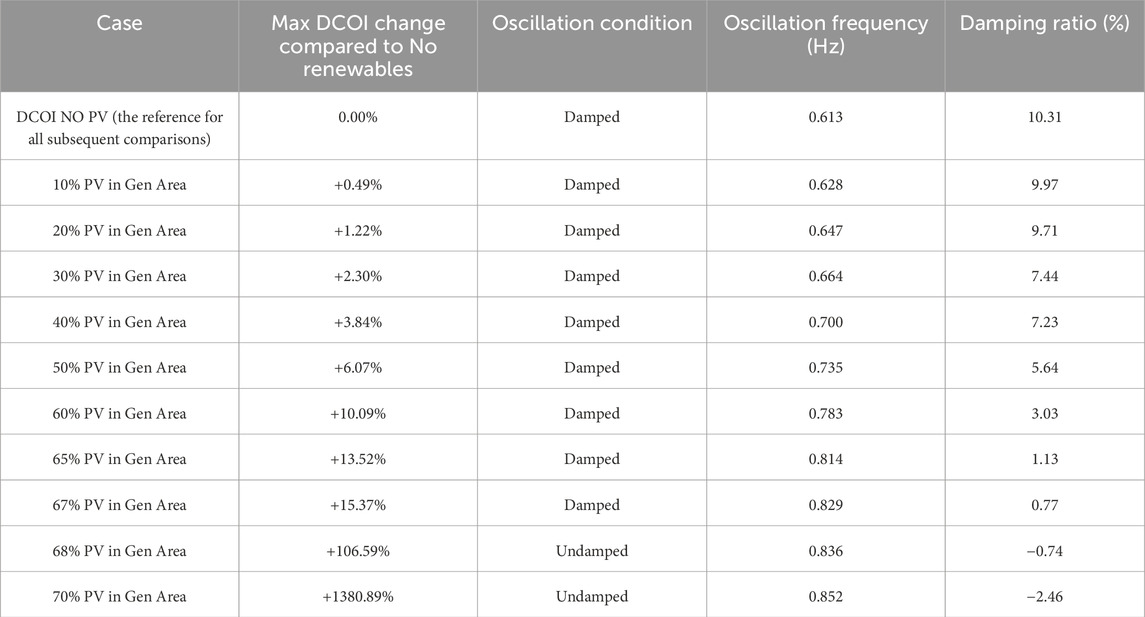
Table 1. Max Distance to the center of inertia when the system penetration increased in the generation area only.
The dominant oscillatory mode frequency steadily increases with PV penetration, while its damping ratio consistently falls. In the data, the mode drifts upward from 0.613 Hz (no PV) to 0.852 Hz (70% PV). At the same time, the reported modal damping (in %) declines from about 10.3 at baseline to below 1.0 by 67% PV. This behavior matches expectations from reduced system inertia: replacing synchronous machines with inverter-based PV raises mode frequency and tends to erode damping.
Most critically, the system remains damped (stable) up to 67% PV but becomes undamped (unstable) at about 68% PV, as indicated by a negative damping ratio. In the table, the “Condition SSS” flag is “Damped” through 67% PV and flips to “Undamped” at 68%. The loss of damping at this point is reflected in the DCOI surge noted above.
To mitigate the destabilizing impacts of high PV penetration, Battery Energy Storage Systems (BESS) are installed in local areas alongside clustered PV photovoltaic plants. Two schemes are envisioned, Grid-Following (GFL) and Grid-Forming (GFM).
The primary objective of integrating BESS in this research is to achieve system stability, as the maximum change in Distance to the Center of Inertia (DCOI) is limited to a range of 15%–17.5% compared to the no-renewable baseline. This limit allows adequate damping of the highest amplitude oscillation mode without too much storage capacity. The BESS models’ optimization strategies are designed to optimize the input to the lowest rated power and energy of the BESS size, ensuring the models meet the DCOI and damping requirements.
3.2 Mitigation with BESS
3.2.1 PSO-optimized BESS GFL
A Grid-Following (GFL) Battery Energy Storage System (BESS) has been installed to counter the instability of 70% PV in the generation zone, and the optimal parameter tuning by Particle Swarm Optimization (PSO) is performed to accomplish this task. The optimization process identified not only the minimum size of BESS, but also the values of the PID controller gains needed to achieve a desired level of system damping and constrain the excursion of Distance to the Center of Inertia (DCOI).
The obtained structure worked with a 30 MW GFL BESS with PSO-optimized PID parameters. Such a configuration has provided a significant enhancement of the stability of systems. The greatest variation in DCOI dropped drastically to +16.96%, where in the uncontrolled case, the variation was 1380.89%, putting this system in a stable window with a predefined range of maximum DCOI variation. Moreover, the GFL BESS succeeded in damping the grid to the dominant inter-area oscillation mode that lacked damping at 70% PV and significantly re-achieved small-signal grid stability without needing grid-forming capability.
To prove the dynamic behavior of the optimal control, the time-domain simulation was run within a harsh contingency: a 3-phase fault on the transmission line between bus 7 and 8. A 0.1 s was allowed, after which the fault was cleared and the system response monitored. Two important variables were analyzed, which included the angle difference between the two significant areas and the active power reaction at the tie-line interconnect.
The findings advocate the advantages of the optimized GFL BESS. In the absence of any BESS, the system exhibits oscillations in both the angle and power flow, leading to the observation of undamped modes. However, when an optimized GFL BESS is used, i.e., with a PSO-optimized version, oscillations are much dampened. The difference of angles settles down promptly and shows a smooth convergent reaction as in Figure 2. These results substantiate the fact that, correctly sized and tuned, a GFL-configured BESS can deliver effective damping of oscillations and lead to improved transient stability in high-renewable systems.
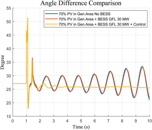
Figure 2. Angle difference response between the two areas for the system response of a line fault.
The comparative analysis was conducted to determine the optimal size of the grid-following ESS, which would effectively damp the dominant oscillation mode and bring the maximum Distance to the center of inertia (COI) back into the stable area. The paper was based on testing of a range of capacities of ESS 20 MW, 25 MW, and 30 MW. According to the PSO sizing approach employed as described in Section 2.4, an optimized capacity of 30 MW grid-following ESS was found. This was necessary to achieve the desired damping and to stay within the range of the maximum Distance to the COI, which returned to the stable range as shown in Figures 3, 4. The finding based on this indicates the need to properly size the BESS to suppress oscillatory instability and maintain robust system dynamics.
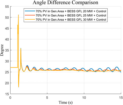
Figure 3. Angle difference response between the two areas for the system response of a line fault.
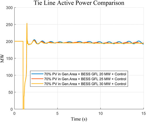
Figure 4. Tieline active power response for the system response to a line fault.
3.2.2 PSO-optimized BESS GFM
In a similar case, where PV penetration reached 70%, a Grid-Forming (GFM) BESS, as described previously, was also implemented and adjusted through PSO. There is further dynamic support to variable voltages and frequencies by the GFM BESS that acts like a virtual synchronous machine.
Amazingly, the GFM BESS attained stability conditions with a 10 MW installation, which is significantly smaller than GFL. The percentage deviation of DCOI in the optimized GFM BESS was limited to +16.09% at most, within a safe margin of 3% to +25%, that is, within a stable operational margin.
The better performance of the GFM configuration was also confirmed in time-domain simulations, which were based on an identical severe fault scenario (three-phase fault cleared after 0.1 s). Angular difference and tie-line power response oscillations were suppressed quickly, and the rate of convergence was even faster, causing an insignificant amount of residual oscillations. Moving on to the point where a larger 30 MW GFL BESS was directly compared against this, achieving a total of 30 MW peak power and 30 MW holding power, it is noted in Figures 5–8 that this still demonstrated commendable performance.
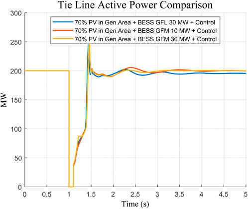
Figure 5. Tieline active power response for the system response to a line fault.
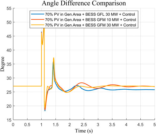
Figure 6. Angle difference response between the two areas for the system response of a line fault (Zoomed Case).
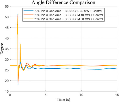
Figure 7. Angle difference response between the two areas for the system response of a line fault.
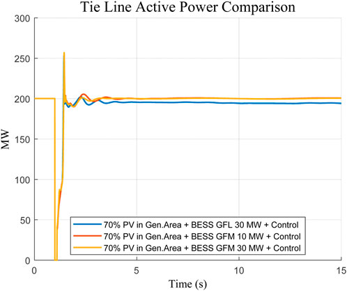
Figure 8. Tieline active power response for the system response to a line fault.
The given findings support the effectiveness and increase the dynamic capabilities of GFM BESS technology. GFM-based solutions have much lower power ratings than GFL equivalents and can therefore provide greater stability and are especially beneficial in high-renewable, low-inertia grid applications.
4 Discussion of key findings
This paper presents several findings on the challenges of small-signal stability and transient stability posed by high photovoltaic (PV) penetration in a two-area power system, as well as the efficacy of BESS-based mitigation measures. The stability of the Distance to the Center of Inertia (DCOI) stability index and trends in modal damping were analyzed together with the effect of optimally controlled Battery Energy Storage Systems (BESS) in both Grid-Following (GFL) and Grid-Forming (GFM) operations.
One of the findings is the sharp growth of the deviation of the DCOI with the increase in the PV penetration rate to 68%–70%. The system is only marginally stable up to 67% PV, but a qualitative transition to instability takes place after that value. This transition is characterized by a sudden increase in DCOI (from ∼13 to over 1,300%) as well as a change in modal damping to go negative.
These results highlight that the level of renewable integration achievable with a high level of concentration can provide critical thresholds where the natural inertia and damping of the system are not adequate to maintain oscillatory stability. The predominant mode reaches the condition of being lightly damped and eventually unstable even to little disturbances, emphasizing the necessity of fast and adaptive control action. In this regard, the best-tuned BESS units come out as valuable stabilizing assets.
The GFL BESS, with a PSO-optimal power economy of at least 30 MW, managed to bring the DCOI closer to the target gain against the limit during the leading period oscillation, achieving a 16.96% gain, and restored damping in the leading oscillatory mode.
Nonetheless, the findings indicate that GFM BESS is a better performer in comparison to GFL competitors. With a relatively low power rating of 10 MW, the GFM setup achieved a similar magnitude of reduction in DCOI deviation (+16.09%). It provided better transient suppression in the event of a line fault. This is supplied by the active grid frequency and voltage control of GFM inverters due to their intrinsic ability to behave like conventional synchronous machines and add to system strength, even in extremely low-inertia situations.
In addition, the passing analysis of the fault condition between bus seven and bus eight will also confirm this fact. GFM BESS also stabilized the inter-area angle difference, apart from the smooth variation of tie-line power flow, which also converged faster once and had a lower overshoot in comparison with the GFL-controlled case.
Such findings further confirm a steady trend in the literature that GFM inverters will be an indispensable component in grids with high penetration of inverter-based resources to achieve grid stability. In general, the paper proves that although both BESS types can be tuned to accomplish similar DCOI-based stability goals, GFM realization is a much more powerful and dynamically safe solution. The practical implications of these findings are that a more cost-effective route towards grid stability can be found in the form of GFM-capable storage in future high-penetrant renewable power systems and planning.
5 Conclusion
The paper has analyzed the small-signal stability issues of power systems with renewable dominance, specifically not only on cluster-type photovoltaic (PV) integration but also on inverter-based storage. The results indicate that the clustered deployment of PV will generate an uneven distribution of inertia and cause some areas to be more prone to low-frequency variations and inter-area instability.
A comparative evaluation of grid-following (GFL) and grid-forming (GFM) storage helps to understand that both methods improve stability; however, they are quite different. Storage with GFL has relative improvements, and since it relies on phase-locked loop synchronization, it becomes rather delicate in weak-grid conditions. Conversely, GFM-based storage is always more damping, placing critical eigenvalues further in the stable spectrum, and more effectively damped oscillatory modes, both at high PV penetration.
As shown in the results, GFM control strategies are more resilient in mitigating small-signal instability in renewable-heavy grids. Nevertheless, care should be taken in control design, coordination of the system, and developing grid codes to implement it appropriately.
Overall, this study highlights the relevance of implementing grid-forming storage systems in fortifying the oscillatory stability of low-inertia systems in the future. Future work is needed in several areas, including hybrid GFL-GFM approaches, practice pilot projects, and determining the appropriate size of energy storage systems to make renewable-dominant grids trustworthy and resilient.
Data availability statement
The original contributions presented in the study are included in the article/supplementary material, further inquiries can be directed to the corresponding author.
Author contributions
IA: Project administration, Formal Analysis, Validation, Methodology, Supervision, Data curation, Conceptualization, Software, Resources, Writing – review and editing, Investigation, Visualization, Funding acquisition, Writing – original draft.
Funding
The author(s) declare that no financial support was received for the research and/or publication of this article.
Conflict of interest
The author declares that the research was conducted in the absence of any commercial or financial relationships that could be construed as a potential conflict of interest.
Generative AI statement
The author(s) declare that no Generative AI was used in the creation of this manuscript.
Any alternative text (alt text) provided alongside figures in this article has been generated by Frontiers with the support of artificial intelligence and reasonable efforts have been made to ensure accuracy, including review by the authors wherever possible. If you identify any issues, please contact us.
Publisher’s note
All claims expressed in this article are solely those of the authors and do not necessarily represent those of their affiliated organizations, or those of the publisher, the editors and the reviewers. Any product that may be evaluated in this article, or claim that may be made by its manufacturer, is not guaranteed or endorsed by the publisher.
References
Abumeteir, H. A., and Vural, A. M. (2022). Design and optimization of fractional order PID controller to enhance energy storage system contribution for damping low-frequency oscillation in power systems integrated with high penetration of renewable sources. Sustainability 14 (9), 5095. doi:10.3390/su14095095
Arraño-Vargas, F., Jiang, S., Bennett, B., and Konstantinou, G. (2023). Mitigation of power system oscillations in weak grids with battery energy storage systems: a real-world case study. Energy 283, 128648. doi:10.1016/j.energy.2023.128648
Assery, S. A., Zhang, X., and Chen, N. (2023). Large-scale BESS for damping frequency oscillations of power systems with high wind power penetration. Inventions 9 (1), 3. doi:10.3390/inventions9010003
Deželak, K., Bracinik, P., Sredenšek, K., and Seme, S. (2021). Proportional-integral controllers performance of a grid-connected solar PV system with particle swarm optimization and ziegler–nichols tuning method. Energies 14 (9), 2516. doi:10.3390/en14092516
Electric Power Research Institute (EPRI) (2018). Model user guide for generic renewable energy system models. Available online at: https://www.epri.com/research/products/000000003002012642.
Gajare, P. M., Benzaquen, J., and Divan, D. (2025). Grid-forming controller with enhanced disturbance rejection. IEEE J. Emerg. Sel. Top. Power Electron. 13 (4), 5201–5217. doi:10.1109/JESTPE.2025.3571573
Han, F., Zhang, X., Li, M., Li, F., and Zhao, W. (2024). Stability control for grid-connected inverters based on hybrid-mode of grid-following and grid-forming. IEEE Trans. Industrial Electron. 71 (9), 10750–10760. doi:10.1109/TIE.2023.3335325
Hu, Y., Bu, S., Zhou, B., Liu, Y., and Fei, C.-W. (2019). Impedance-based oscillatory stability analysis of high power electronics-penetrated power systems—A survey. IEEE Access 7, 120774–120787. doi:10.1109/ACCESS.2019.2937395
Ji, X., Liu, D., Jiang, K., Zhang, Z., and Yang, Y. (2024). Small-signal stability of hybrid inverters with grid-following and grid-forming controls. Energies 17 (7), 1644. doi:10.3390/en17071644
K, G., and Jena, M. K. (2023). A practical approach to inertia distribution monitoring and impact of inertia distribution on oscillation baselining study for renewable penetrated power grid. IEEE Syst. J. 17 (3), 3593–3601. doi:10.1109/JSYST.2022.3228966
Khan, S. A., Wang, M., Su, W., Liu, G., and Chaturvedi, S. (2022). Grid-forming converters for stability issues in future power grids. Energies 15 (14), 4937. doi:10.3390/en15144937
Liu, P., Xie, X., and Shair, J. (2024). Adaptive hybrid grid-forming and grid-following control of IBRs with enhanced small-signal stability under varying SCRs. IEEE Trans. Power Electron. 39 (6), 6603–6607. doi:10.1109/TPEL.2024.3373659
Mirmohammad, M., and Azad, S. P. (2024). Control and stability of grid-forming inverters: a comprehensive review. Energies 17 (13), 3186. doi:10.3390/en17133186
Mosca, C., Arrigo, F., Mazza, A., Bompard, E., Carpaneto, E., Chicco, G., et al. (2019). Mitigation of frequency stability issues in low inertia power systems using synchronous compensators and battery energy storage systems. IET Generation, Transm. and Distribution 13 (17), 3951–3959. doi:10.1049/iet-gtd.2018.7008
Njoka, G. M., Mogaka, L., and Wangai, A. (2025). Enhancing grid stability and resilience through BESS optimal placement and sizing in VRES-Dominated systems. Energy Rep. 13, 1764–1779. doi:10.1016/j.egyr.2025.01.028
Pacific Northwest National Laboratory (2023). Model specification of droop-controlled, grid-forming inverters (REGFM_A1). Richland, United States: U.S. Department of Energy. Available online at: https://www.osti.gov/servlets/purl/2229442.
Prabpal, P., Kongjeen, Y., and Bhumkittipich, K. (2021). Optimal battery energy storage system based on VAR control strategies using particle swarm optimization for power distribution system. Symmetry 13 (9), 1692. doi:10.3390/sym13091692
Pulgar-Painemal, H., Wang, Y., and Silva-Saravia, H. (2018). On inertia distribution, inter-area oscillations, and location of electronically-interfaced resources. IEEE Trans. Power Syst. 33 (4), 995–1003. doi:10.1109/TPWRS.2017.2688921
Rudnik, V. E., Ufa, R. A., and Malkova, Y. Y. (2022). Analysis of low-frequency oscillation in power system with renewable energy sources. Energy Rep. 8 (Suppl. 9), 394–405. doi:10.1016/j.egyr.2022.07.022
Singh, A., Debusschere, V., Hadjsaid, N., Legrand, X., and Bouzigon, B. (2024). Slow-interaction converter-driven stability in the distribution grid: small-signal stability analysis with grid-following and grid-forming inverters. IEEE Trans. Power Syst. 39 (2), 4521–4536. doi:10.1109/TPWRS.2023.3319708
Wang, Y., Silva-Saravia, H., and Pulgar-Painemal, H. (2019). Actuator placement for enhanced grid dynamic performance: a machine learning approach. IEEE Trans. Power Syst. 34 (4), 3119–3128. doi:10.1109/TPWRS.2019.2895019
Western Electricity Coordinating Council Renewable Energy Modeling Task Force (2014). WECC solar plant dynamic modeling guidelines. WECC Model. Validation Work Group. Available online at: https://www.wecc.org/_layouts/15/WopiFrame.aspx?sourcedoc=/Reliability/WECC%20Solar%20Plant%20Dynamic%20Modeling%20Guidelines.docx.
Yang, C., Huang, L., Xin, H., and Ju, P. (2021). Placing grid-forming converters to enhance small signal stability of PLL-integrated power systems. IEEE Trans. Power Syst. 36 (4), 3563–3573. doi:10.1109/TPWRS.2020.3042741
Keywords: small-signal stability, grid-following inverters (GFL), grid-forming inverters (GFM), energy storage systems (ESS), clustered photovoltaic (PV) systems, renewable-dominated grids
Citation: Altarjami I (2025) Small-signal stability in renewable-dominated grids: a comparative analysis of GFL and GFM storage for clustered PV mitigation. Front. Energy Res. 13:1691710. doi: 10.3389/fenrg.2025.1691710
Received: 24 August 2025; Accepted: 21 October 2025;
Published: 14 November 2025.
Edited by:
Rui Fan, University of Denver, United StatesReviewed by:
Guochu Chen, Shanghai Dianji University, ChinaIstiyo Winarno, Universitas Hang Tuah, Indonesia
Copyright © 2025 Altarjami. This is an open-access article distributed under the terms of the Creative Commons Attribution License (CC BY). The use, distribution or reproduction in other forums is permitted, provided the original author(s) and the copyright owner(s) are credited and that the original publication in this journal is cited, in accordance with accepted academic practice. No use, distribution or reproduction is permitted which does not comply with these terms.
*Correspondence: Ibrahim Altarjami, aXRhcmptaUB0YWliYWh1LmVkdS5zYQ==