 Zhen Huang
 Kaiyuan Hou
- Northeast Branch of State Grid Corporation of China, Shenyang, China
For frequency and voltage stability control of grid-forming converters in high-power electronic scenarios, this paper proposes a grid-forming converter grid-connection stability control strategy based on passive control and deep reinforcement learning. Firstly, the virtual synchronous generator (VSG) is written in the port-Hamiltonian form to clarify the interconnection and dissipative structure, and the achievable passive control law is obtained by energy shaping and damping injection. Then, DDPG is introduced to adjust the damping parameters online, so that the control has adaptive ability under multiple working conditions, and the closed-loop system is proved to be asymptotically stable based on Lyapunov function. Finally, the simulation example analysis is carried out. In the simulation of power mutation, voltage imbalance, short-circuit fault and load change, this method significantly reduces the overshoot and adjustment time compared with VSG-PI and fixed parameter PBC, and improves the steady-state error and energy dissipation rate. The simulation results verify the effectiveness of the combination of physical consistency and strategy adaptation.
1 Introduction
With the continuous advancement of the goal of reducing carbon and consumption energy system construction, the global new energy grid-connected system has developed rapidly. (Shao et al., 2025; Xia et al., 2025). However, with the increasing proportion of power electronic devices in renewable energy power generation systems, especially the increase of power electronization rate caused by the expansion of wind power installation scale, the damping and inertia characteristics provided by synchronous generators in the system are significantly weakened, and the support ability of the power grid to wind power integration is reduced, which has an important impact on the stable operation of new energy grid-connected systems (Liu et al., 2023; Ji and Xu, 2024; Liu et al., 2024). In order to enhance the stability of the new energy grid-connected system, the grid-forming converter has received extensive attention as a technology that can actively provide support functions such as frequency modulation and voltage regulation. At present, the mainstream network-based control strategies mainly include four categories: droop control, virtual synchronizer control, matching control and virtual oscillator control. The droop control cannot directly respond to the frequency change rate of the system; the virtual synchronous machine control has the inertia support function, which can realize the direct response to the system frequency change rate. Matching control and virtual oscillator control are new control methods proposed in recent years. (Wang et al., 2022; Rocabert et al., 2012). Focusing on the control research of the grid-forming converters, the model bionic method represented by VSG introduces virtual inertia and damping by means of the rotor motion equation to improve the frequency support capability. In addition, the energy shaping method based on dissipative Hamiltonian or port-controlled theory can improve the stability margin of nonlinear links through interconnection-dissipative structure reconstruction. Building upon this foundation, the data-driven method represented by deep reinforcement learning emphasizes strategy adaptation under multi-disturbance and parameter uncertainty. While existing approaches have made progress in their respective dimensions, they generally face limitations such as linear PI parameters struggling to cover strong nonlinearities, fixed energy-shaping parameters failing to adapt to multiple operating conditions, and data-driven strategies lacking physical consistency constraints.
In this paper, a network construction control method based on VSG is adopted. This strategy introduces virtual inertia by simulating the dynamic characteristics of the synchronous generator, so that the system can provide inertia and damping support independently without relying on the phase-locked loop (Liu et al., 2017; Wang et al., 2023). However, due to the high fitting of the external characteristics of the synchronous machine, the scheme sacrifices the original fast response performance of the converter to a certain extent. In addition, VSG control models the new energy grid-connected system as a second-order system, which is more likely to cause stability problems under non-ideal conditions such as power fluctuation, grid voltage imbalance, short-circuit fault and load change. In terms of improving the control performance of grid-forming converters, several studies have proposed improvement schemes. In reference (Sang et al., 2021), a virtual synchronous direct-drive wind power control system based on DC voltage synchronization is designed. The complex power coefficient method is used to identify the key factors affecting the stability, and the corresponding stabilization control strategy and parameter tuning method are proposed to enhance the inertia response capability of the system. Reference (Cheng et al., 2023) reports a VSG control method based on the output stage, which suppresses the power fluctuation by introducing a current regulator to stabilize the output current oscillation. Based on the fourth-order generator model, the adaptive terminal sliding mode control law is constructed in reference (Yan and Wang, 2018), which realizes the error-free adjustment of the VSG excitation link, overcomes the uncertainty caused by the perturbation of the filter parameters, and improves the stability margin of the system. In reference (Dang et al., 2021), sliding mode control is applied to the inner current loop of the converter, and the robustness of the system after disturbance is enhanced by adjusting the grid-connected power factor. Although the above research has promoted the development of VSG control, most of the existing strategies do not fully consider the nonlinear dynamic behavior of the grid-connected system. The linear proportional integral control method is still widely used, and its control performance still has room for improvement.
Passive control has the advantages of simple structure, low cost, strong robustness and easy implementation (Ortega et al., 2008; Cheng et al., 2024). The grid-connected system under grid-type control is essentially a nonlinear system, and the linear control method is often less stable. This kind of method usually needs to simplify the nonlinear part of the system, which leads to the deviation between the model and the actual system, and it is difficult to achieve effective and stable control of power, frequency and voltage (Zhang et al., 2021). In addition, the parameter optimization effect of virtual synchronous generator (VSG) is limited, and its fixed parameters are difficult to adapt to the dynamic changes of power grid conditions. The passivity-based control method is based on the structural characteristics of the system. The controller is designed from the perspective of the energy function, and the system is asymptotically stable by reconstructing the generalized energy function. This method does not need to introduce complex nonlinear functions or observers, and the parameter tuning is simple. Reference (Cheng et al., 2019) combines passive control with shunt active filter to realize reactive power and harmonic compensation under non-ideal conditions, which improves system stability. In reference (Liu et al., 2021), an adaptive passive control strategy based on dissipative Hamiltonian model is proposed for doubly-fed wind turbines, which can effectively suppress forced subsynchronous oscillation. Reference (Cheng et al., 2017) proposed a converter control strategy based on internal model observer and passive theory to reduce the damage of grid imbalance to doubly-fed wind turbines. Reference (Chen et al., 2019) applied the passive control of the Euler-Lagrange model to the modular multilevel converter under unbalanced grid conditions, which enhanced the stability of the system. In summary, the research on passive control in power system direction is mainly applied to the machine side and the grid side (Xue et al., 2022; Liu et al., 2023; Xue et al., 2020). The machine side mainly studies direct-drive and doubly-fed wind turbines, and the grid side mainly studies two-level converters, modular multi-level converters, etc., which have not been applied to the grid control. Therefore, this paper applies passive control to the virtual synchronous control equation to make up for the shortcomings of the linear control method‘s lack of adaptability to model errors and parameter changes and improve system stability. In response to the above shortcomings, this paper proposes a two-layer control strategy of physical mechanism hybrid strategy learning. The lower layer uses passive control to perform energy shaping and damping injection on VSG to ensure structural stability and convergence; DDPG is introduced by the upper layer to adjust the PBC damping injection parameters online, enabling the control law to adaptively approximate optimal performance under different faults, disturbances and weak network conditions.
In summary, this study investigates the grid-connected stability of grid-forming converters based on the VSG control principle. A Hamiltonian energy shaping-based control strategy derived from passivity theory is proposed to regulate angular frequency and voltage. The main features are as follows.
1. Passive control belongs to the category of nonlinear control theory, which is extremely in line with the nonlinear characteristics of the system, and the controller is designed through Hamilton’s energy molding control method, which has excellent VSG output control ability, fast response and accurate control.
2. By introducing a damping mechanism, the system energy can be reconfigured and the energy function can be optimized, so that the angular frequency and voltage of the VSG output can be stabilized within the desired equilibrium range, and the robustness and stability of the system can be enhanced under non-ideal system conditions.
3. The strategy is able to quickly track the system desired balance point and synchronize the tracking of angular frequency and voltage changes under the non-ideal conditions of power change, grid voltage imbalance, short-circuit faults, and load changes in the simulated working conditions, the advantages of the proposed method are quantitatively explained from the indexes of adjustment time, overshoot, steady-state error and energy dissipation rate, which greatly improves the frequency stability of the system.
2 Main topology and control principle of grid-forming converter
2.1 Main topology of grid-forming converter
The cooperative control of the grid-forming converter refers to the closed-loop cooperation between the passive energy shaping of the physical layer and the adaptive setting of the damping parameters of the intelligent layer. The physical layer guarantees the provable stability through the Hamiltonian energy function and the interconnection-dissipative structure; the intelligent layer takes the system state as the observation and the damping adjustment as the action, and optimizes the dynamic performance online without destroying the passive structure. The grid-type control system mainly contains the grid-side converter, filter, grid impedance, etc. The virtual synchronization control used in this paper is the main topology of the grid-type converter. In this paper, the virtual synchronous control is adopted as the control strategy of the grid-type, and the converter control includes VSG control, power external loop control and voltage-current double closed-loop control. The VSG main topology is shown in Figure 1.
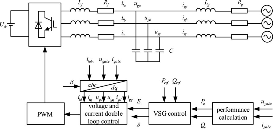
Figure 1. Main topology and control structure of grid-forming converter.
2.2 Mathematical model and control strategy of VSG
Virtual synchronous control mimics the electromechanical dynamics of synchronous generators, with its core functionality consisting of active-frequency power and reactive-voltage power control loops.
The specific equations of active power-frequency regulation are shown in Equation 1.
where,
The specific equation of reactive voltage regulation is shown in Equation 2
where,
The active-frequency control incorporates the rotor motion equation, as shown in Equation 1, thereby enabling the provision of inertia support to the grid-connected system via the grid-forming converter, which is shown in Figure 2.
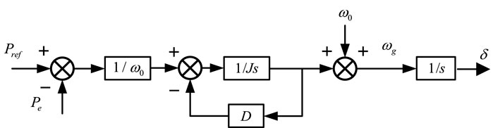
Figure 2. VSG active frequency control structure diagram.
The reactive power-voltage control module adjusts the grid-connected reactive power through the excitation voltage regulation function, thereby generating the reactive power output voltage required for the grid-forming converter, which is shown in Figure 3.
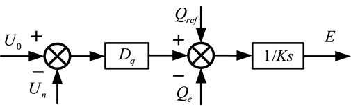
Figure 3. VSG reactive voltage regulation control block diagram.
3 Passive control design based on VSG
3.1 Hamiltonian model and passivity analysis of VSG
The concept of passivity is derived from the dissipation property, which shows the behavior of a dynamical system by describing the interaction between the internal energy of the system and the external energy, therefore passive control theory achieves the control objective by considering the VSG as an energy exchanger, setting the energy function related to the control objective and designing a passive controller, which minimizes the energy of the system at the desired point while ensuring that the system is asymptotically stabilized (Hua et al., 2022). Passive control is a nonlinear control strategy, the core idea of this method is based on the principle of passivity, the system increases the energy less than the external injected energy, and the control objective reaches the desired point quickly by injecting damping.
Taking
Under the port mapping
where,
The following standard port-Hamiltonian form is obtained:
where,
The coefficient matrix in Equation 6 is:
The Hamiltonian function
where,
According to the theory of passivity, the dissipation inequality reflecting the energy change of the system is shown in Equation 8.
where,
Since
This does not affect the system energy change and need not be considered when calculating the damping injection, thus simplifying the design step of the passive controller.
3.2 Passive control design of VSG
Under non-ideal conditions, the VSG angular frequency and output voltage will fluctuate, in order to improve the system stability, they are set as the controlled physical quantities for the system desired equilibrium point configuration, and the passive control is able to control the controlled physical quantities to the corresponding desired values, therefore, the desired point of the VSG control system is set as shown in Equation 10.
where,
The damping term is added to accelerate the energy dissipation of the system, which is obtained by the interconnection and damping allocation method as shown in Equation 11.
where,
From the above equation, the control law
Both sides of Equation 13 are simultaneously multiplied by
where,
Substituting Equation 15 into the relevant parameters, we can get Equation 16.
The passive control law based on VSG can be obtained by opening Equation 12:
The passive control system structure is shown in Figure 4, where the reactive power reference value is set to zero.
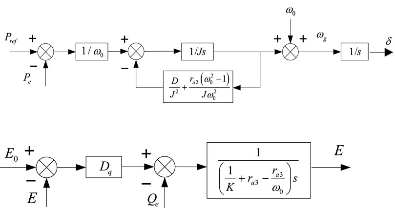
Figure 4. Passivity-based control block diagram.
According to the expected equilibrium point
From the port-Hamiltonian model is shown in Equation 19.
Under the closed-loop passive control law, the power of the outer port is balanced, as shown in Equation 20.
At this moment,
3.3 Passive control law optimization based on DDPG algorithm
As mentioned above, passive control accelerates the energy dissipation of the system by injecting damping
The VSG control system is regarded as an environment for reinforcement learning, and the key elements are defined as follows.
1. State
where,
2. Action
where,
3. Reward function
where,
The state vector
DDPG is an offline strategy algorithm based on Actor-Critic architecture, which consists of four neural networks and an experience replay buffer. The intelligent agent performs action
where,
Use policy gradient ascent to update parameters to maximize the expected return is shown in Equation 25.
Soft update strategy to ensure learning stability is shown in Equation 26.
Through the above process, the intelligent agent continuously learns and approaches the optimal strategy
4 Simulation verification results analysis
To validate the effectiveness and superiority of the VSG-oriented control strategy proposed in this paper under various operating conditions, simulation studies are conducted under five scenarios: normal operation, power fluctuations, grid voltage imbalance, short-circuit faults, and load variations. Subsequently, the reliability and dynamic response capabilities of the system are evaluated based on the simulation results of the grid-forming converter system model. All simulations in this paper are performed on the MATLAB/Simulink R2023b platform using a fixed-step discrete solver. The simulated waveforms under different simulation conditions are analyzed to compare the passive control strategy with the virtual synchronous control effect. The system parameters are shown in Table 1, the DDPG algorithm parameters are shown in Table 2.
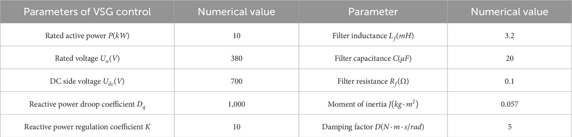
Table 1. System parameters of VSG control.
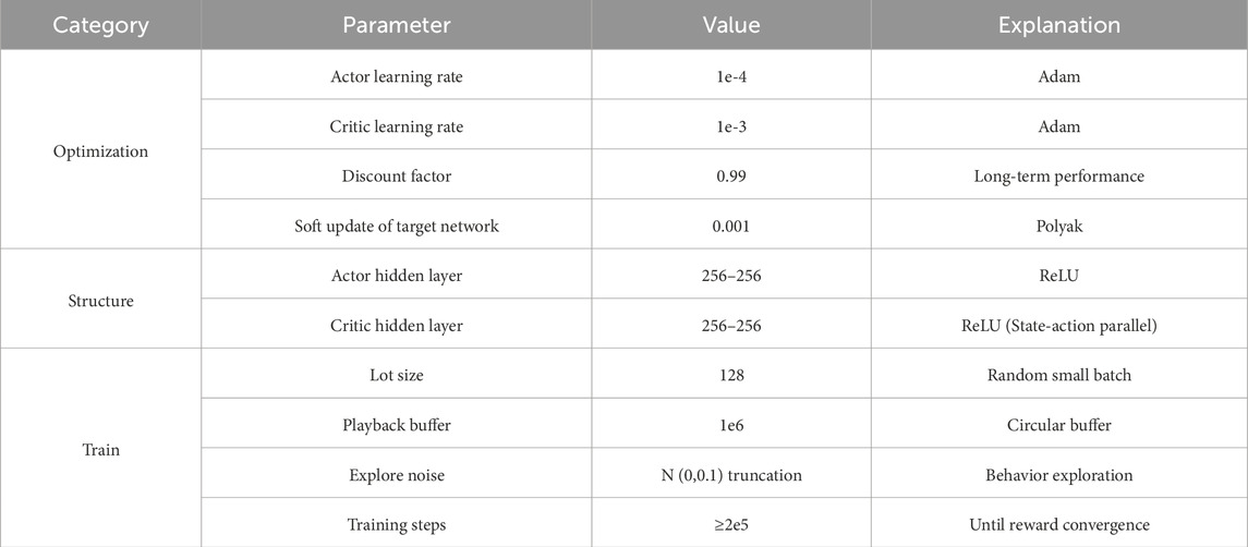
Table 2. DDPG algorithm parameters.
4.1 Steady-state operation simulation
Under normal operating conditions, the simulation waveforms under VSG control and passive control strategy are shown in Figure 5. Where: Figure 5a–d show the active and reactive power, angular frequency, and output voltage of the converter output, respectively. From Figs. a and b, it can be seen that the stable values of active and reactive power are consistent with the data in Table 1; Figs. c and d show that the angular frequency and voltage can quickly and stably track the reference value of the system, and the simulated waveforms under passive control have smaller overshoots and reach the stable values faster, which proves that the proposed strategy has good stabilized operation characteristics.
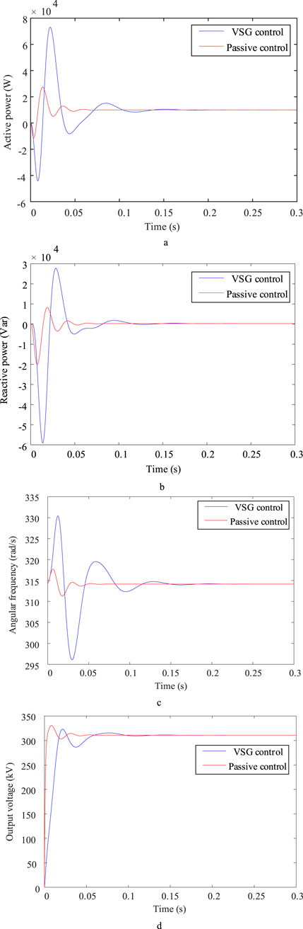
Figure 5. PBC control simulation waveform under normal operating conditions. (a) Converter output active power (b) Converter output reactive power (c) Converter output angular frequency (d) Converter output voltage.
Under steady-state operating conditions, the passive control strategy proposed in this paper shows better dynamic performance than traditional VSG control. The fundamental reason is that the passive control reconstructs the energy flow of the system through energy shaping and damping injection mechanisms. From the perspective of Hamilton energy function, the passive controller makes the system energy function have faster convergence characteristics at the desired equilibrium point by modifying the interconnection matrix and damping matrix of the system. In contrast, traditional VSG control relies on fixed PI parameters, and its response speed and overshoot are limited by the inherent limitations of linear control. Passive control effectively suppresses the energy oscillation of the system in the transient process by injecting an adjustable damping term, thereby achieving smoother power and frequency response. In addition, the nonlinear characteristics of passive control make it better adapt to the inherent nonlinearity of the system and avoid the performance degradation of linear control when the model is mismatched. The results of this section show that passive control can provide better control effect under steady state and small disturbance, which lays a foundation for subsequent simulation under complex working conditions.
4.2 Dynamic operation simulation
4.2.1 Power change working condition
At
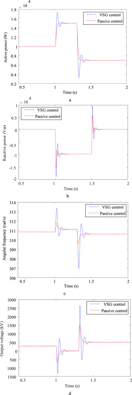
Figure 6. Simulation waveforms of two control strategies when power changes. (a) Converter output active power (b) Converter output reactive power (c) Converter output angular frequency (d) Converter output voltage.
Under the condition of sudden power change, passive control shows faster response speed and smaller overshoot, which is mainly attributed to its control mechanism based on energy dissipation. When the active power reference value changes step by step, the system energy function changes drastically. The passive controller accelerates the redistribution and dissipation of the system energy by adjusting the damping injection amount in real time, so as to quickly converge to a new equilibrium point. It can be seen from Figure 6 that the angular frequency and voltage response curves under passive control are smooth and have no significant oscillation, indicating that it has good transient stability. Further analysis shows that the passive control directly relates the dynamic behavior of the system to the change of the energy function through the Interconnection and Damping Assignment (IDA-PBC) method, and realizes the accurate control of the system state. In contrast, due to the dependence on fixed parameters, the traditional VSG control is prone to overshoot and oscillation when the power suddenly changes, and the response is slow. In this study, the adaptive ability and robustness of the system under power disturbance are significantly improved by the nonlinear energy management mechanism of passive control.
4.2.2 Grid voltage unbalance condition
When
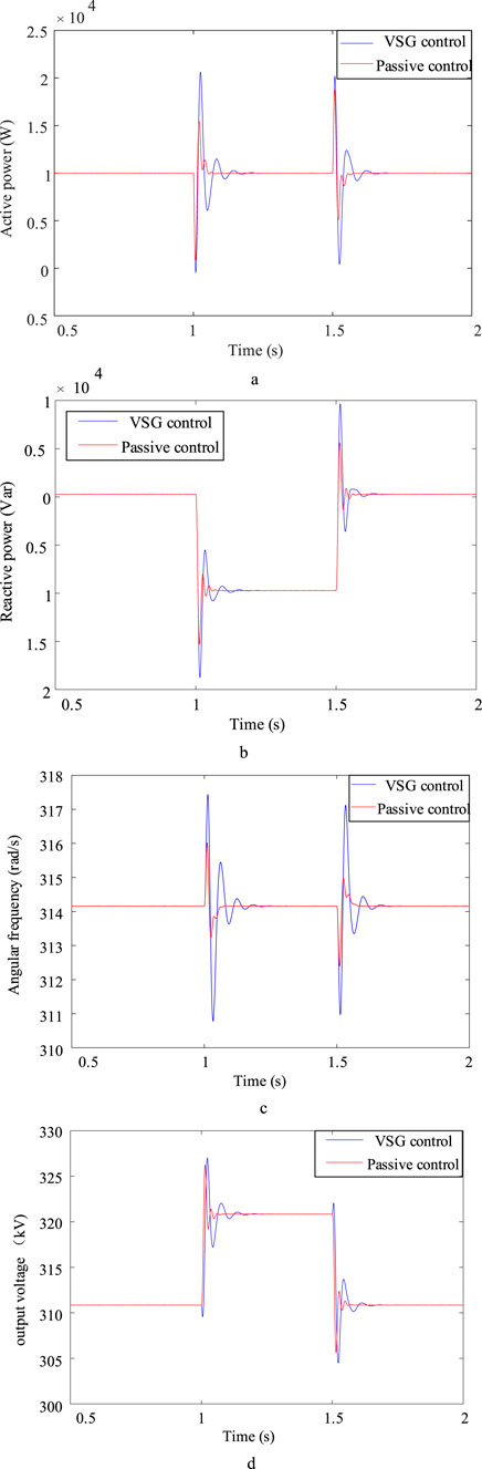
Figure 7. Simulation waveforms of two control strategies when grid voltage rises. (a) Converter output active power (b) Converter output reactive power (c) Passive control output angular frequency (d) Passive control output voltage.
The unbalanced grid voltage condition is an important test for the robustness of the control system. The passive control strategy proposed in this paper can still maintain good dynamic performance in the case of voltage swell, and its core advantage is that its energy-shaping control framework can effectively cope with external disturbances. When the grid voltage changes asymmetrically, the system energy function is asymmetrically distributed. The passive controller reconfigures the system energy flow by adjusting the damping matrix and the interconnection structure, forcing the system state to quickly track the new equilibrium point. It can be seen from Figure 7 that the voltage and frequency response curves under passive control transition smoothly without obvious jitter, indicating that it has strong anti-interference ability. In addition, the passive control does not depend on the symmetry assumption of the grid voltage, so it can still maintain good performance under non-ideal grid conditions. In contrast, the traditional VSG control is prone to power oscillation and frequency fluctuation when the voltage is unbalanced, and its performance is limited by the linear characteristics of the control structure. This study further verifies the applicability and superiority of passive control in non-ideal grid environment.
4.2.3 Short circuit fault condition
When
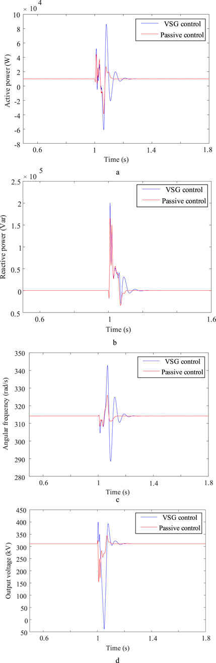
Figure 8. Simulation waveforms of two control strategies in short-circuit fault. (a) Converter output active power (b) Converter output reactive power (c) Passively controlled output angular frequency (d) Passively controlled output voltage.
Short-circuit fault is one of the most serious transient processes in power system, which puts forward high requirements for the dynamic response and stability of the control system. The passive control strategy proposed in this paper shows good robustness and fast recovery ability during short-circuit fault. The control mechanism is to reshape the Hamilton function of the system by energy shaping method, and accelerate the dissipation of energy accumulated during the fault by damping injection, so as to avoid the divergence of the system state. From Figure 8, it can be seen that the active power, reactive power and voltage frequency under passive control can quickly return to a stable value after fault clearance, and the overshoot is significantly smaller than that of traditional VSG control. This performance improvement is due to the nonlinear structure of passive control and the energy-based design concept, which enables it to better deal with the interaction between large disturbances and nonlinearity of the system. In addition, passive control does not require complex fault detection and switching logic, and can achieve adaptive adjustment only through energy feedback, which has strong engineering practical value. The results of this study show that the passive control can still maintain good control effect under extreme fault conditions, which provides a theoretical basis for the application of grid converter in fault ride-through.
4.2.4 Load change condition
In the initial state, the reference value of active power is 10 kW, the load is put into 10 kW at the common connection point at 1 s, and the load is removed at 1.5 s, and the response of the system is observed in 2 s, and the simulation waveforms of passive control of grid-type converter when the load changes are shown in Figure 9. At the beginning stage, the system operates under normal operating conditions, and at 1s the load is suddenly increased by 10 kW, and in order to maintain the power unchanged, the VSG reactive power is rapidly increased to reach a new stable value; at 1.5 s the load surge ends, and the VSG reactive power returns to the original stable value. In 1 s and 1.5 s when the working conditions change, the angular frequency and output voltage are able to reach the new working value quickly and run stably; after the load change, under the action of passive control, the angular frequency and output voltage of the system VSG output are smaller in overshooting compared to that of the traditional VSG control, and return to the stable value more quickly. The connected load adopts a resistance-inductance hybrid model with a power factor of 0.95. This setting reflects the common inductive characteristics of industrial scenarios, which is conducive to examining the impact of reactive power coupling on voltage regulation.
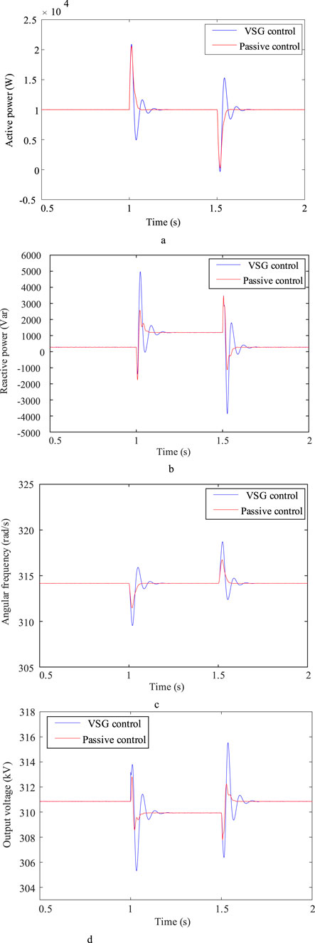
Figure 9. Simulation waveforms of two control strategies when the load changes. (a) Converter output active power (b) Converter output reactive power (c) Passively controlled output angular frequency (d) Passive control output voltage.
Under the sampling period
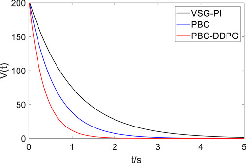
Figure 10. Energy function dissipation curve.
As shown in Figure 10, the Lyapunov energy function
4.2.5 Dynamic performance evaluation
The operation state of grid-forming converter under weak grid and multi-disturbance conditions is usually affected by many kinds of dynamic factors. In order to quantitatively verify the transient characteristics of the above control strategy, the overshoot, adjustment time and steady-state error of angular frequency and output voltage are extracted respectively under two typical working conditions of power step and two-phase short-circuit fault. At the same time, the slope of energy function with time reflects the energy dissipation and dynamic recovery speed of the system. In the evaluation process, a unified 1% steady-state error band is used as the adjustment time criterion to ensure that the comparison of different control modes has a consistent basis.
The dynamic performance formed according to the simulation data is shown in Table 3. The results show that in the power step scenario, compared with the traditional VSG-PI control, the angular frequency overshoot of the PBC-DDPG cooperative strategy is reduced from 13.5% to 4.1%, and the adjustment time is shortened from 0.58 s to 0.26 s. In the short-circuit fault clearing stage, the steady-state error decreases from 2.4% to 0.9%, which further verifies the frequency and voltage recovery ability of the proposed control strategy under rapid disturbance of the system.
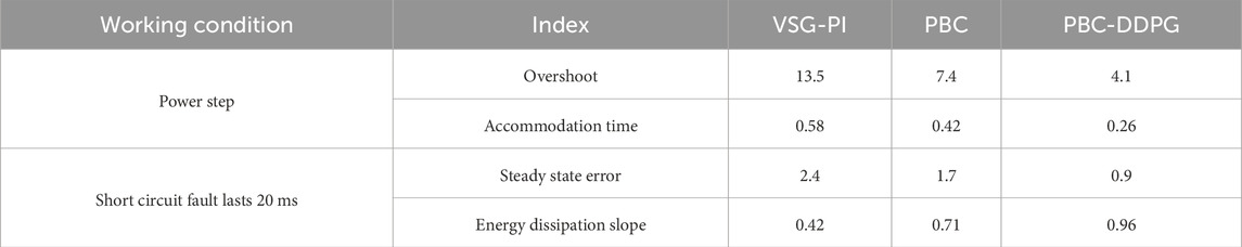
Table 3. Dynamic performance comparison of three control strategies under typical working conditions.
From the data in Table 3, it can be seen that through energy shaping and damping injection, the passive control makes the grid converter have stronger energy release ability, and can quickly suppress the state offset after the disturbance occurs, which shows the synchronous improvement of overshoot and recovery speed. Reinforcement learning makes the damping injection intensity have the adaptive ability of working conditions, so that the control strategy can avoid the performance degradation caused by parameter solidification when switching between different operating states. In the related experiments, the descent speed of the energy function is increased from 0.4 to 0.96, which indicates that the redundant energy in the system dissipates more quickly and avoids the long-term oscillation of the dynamic link. From the perspective of actual operation, the strategy strengthens the dynamic stability margin of the grid-connected converter during accident switching or large-scale power redistribution. When the working condition mutation ratio reaches 50% of the rated output level, the synchronous variable can still be restored to the steady-state operation range within about 0.3 s, which not only improves the transient performance, but also reduces the risk of relay protection action, which is more conducive to the safe and stable operation of the inverter grid-connected system in the low short-circuit capacity area.
5 Conclusion
Aiming at the stability of the angular frequency and output voltage of the grid-type converter under non-ideal conditions, a VSG control strategy based on passive control is proposed, and the following conclusions are obtained through simulation and comparison.
1. The passive control theory is introduced in this paper, and the passive control law based on VSG control model is designed. Under the VSG framework, the structural stability is ensured by Port-Hamiltonian energy shaping and damping injection, and the damping parameters are fine-tuned online by DDPG to adapt to multiple working conditions, so as to achieve comprehensive improvement in key indicators such as overshoot, adjustment time, steady-state error and energy dissipation speed.
2. The passive control significantly improves the dynamic response capability of the grid-structured converter by injecting damping, so that the system can maintain stability under complex operating conditions. Under power fluctuation, grid voltage imbalance, short-circuit faults and load change disturbances, the system is able to maintain good operation capability, with obvious anti-interference ability and excellent system robustness.
3. In this paper, passive control and VSG control are combined to enhance system stability. However, the influence of the damping parameters in the passive control law on the system response has not been fully analyzed.
4. This study provides a new idea for the control of grid-forming converters, that is, the “model-free” learning ability of DRL is used to compensate and optimize the “model-based” control strategy based on physical model, which provides an effective reference for solving the nonlinear and multi-condition control problems in power electronic power systems. The PBC-DDPG strategy proposed in this paper shows better comprehensive performance under various non-ideal conditions such as power mutation, grid voltage imbalance, short-circuit fault and load change, the fast inner loop PBC and slow outer loop DDPG scheduling can ensure the real-time performance of 100 μs inner loop. Compared with VSG-PI, the average computational load increases by about 10%–20%.
Although this study verifies the effectiveness of the proposed strategy, further research can be carried out from the following aspects: Firstly, it is necessary to further explore the quantitative mapping relationship between damping parameters and system dynamic performance in passive control, and establish the parameter design theory of the system to reduce the initial dependence on the optimization algorithm. Secondly, it is necessary to evaluate the universality and scalability of the strategy under different grid strength and converter capacity. Furthermore, the training and verification of the current DDPG algorithm are based on the simulation environment. In the future, it is necessary to solve the engineering practice challenges such as the migration of the agent to the actual physical controller, the embedded deployment and the security guarantee in operation. Finally, this paper focuses on the single-machine system, and the future power grid is bound to be a complex system with multiple grid-forming converters. Therefore, it will be a valuable research direction to extend the framework to multi-airport scenarios and study the distributed cooperative control strategy based on multi-agent reinforcement learning (MARL) to solve the potential oscillation and stability problems in parallel operation.
Data availability statement
The original contributions presented in the study are included in the article/supplementary material, further inquiries can be directed to the corresponding author.
Author contributions
ZH: Writing – original draft, Writing – review and editing. KH: Writing – original draft, Writing – review and editing. DX: Writing – original draft, Writing – review and editing. KW: Writing – original draft, Writing – review and editing. CL: Writing – original draft, Writing – review and editing. XY: Writing – original draft, Writing – review and editing.
Funding
The authors declare that financial support was received for the research and/or publication of this article. This project was supported by Technology Projects of State Grid (5100-202355407A-3-2-ZN).
Conflict of interest
ZH, KH, DX, KW, CL and XY were employed by Northeast Branch of State Grid Corporation of China.
Generative AI statement
The authors declare that no Generative AI was used in the creation of this manuscript.
Any alternative text (alt text) provided alongside figures in this article has been generated by Frontiers with the support of artificial intelligence and reasonable efforts have been made to ensure accuracy, including review by the authors wherever possible. If you identify any issues, please contact us.
Publisher’s note
All claims expressed in this article are solely those of the authors and do not necessarily represent those of their affiliated organizations, or those of the publisher, the editors and the reviewers. Any product that may be evaluated in this article, or claim that may be made by its manufacturer, is not guaranteed or endorsed by the publisher.
References
Chen, M. F., Wang, J. H., Yang, Q. S., and Xia, L. (2019). An improved UPQC topology hybrid passive control. J. Northeast Electr. Power Univ. 39 (06), 78–84. doi:10.19718/j.issn.1005-2992.2019-06-0078-07
Cheng, Q. M., Tan, F. R., Cheng, Y. M., Gao, J., and Zhang, Y. (2017). Research on the control method of DFIG grid-side converter based on internal model observer and passive controller under unbalanced grid. High. Volt. Technol. 43 (10), 3280–3289. doi:10.13336/j.1003-6520.hve.20170925018
Cheng, Q. M., Wang, Y. J., Cheng, Y. M., Shen, L., and Wei, L. (2019). Research on passive control strategy of MMC-SAPF under non-ideal conditions. Chin. J. Electr. Eng. 39 (23), 7023–7032+7115. doi:10.13334/j.0258-8013.pcsee.182425
Cheng, J., Zhao, Z. M., Zhang, L., and Nan, D. L. (2023). VSG-SST control strategy under unbalanced voltage conditions. J. Sol. Energy 44 (03), 393–400. doi:10.19912/j.0254-0096.tynxb.2022-0137
Cheng, Q. M., Wang, H. L., Shen, Z. C., Wang, W. T., Luo, L. H., and Zhang, L. (2024). Passive sliding mode control strategy for Y-source two-stage matrix converter under unbalanced grid. High. Volt. Technol. 50 (11), 4789–4801. doi:10.13336/j.1003-6520.hve.20240447
Dang, C. L., Tong, X. Q., Song, W. Z., and Liu, D. (2021). Current sliding mode control strategy of LCL filter three-phase grid-connected inverter. Power Electron. Technol. 55 (06), 1–4.
Ji, F., and Xu, Z. (2024). Increased LVRT capability for VSG-based grid-tied converters. Appl. Energy 369 (000), 123540. doi:10.1016/j.apenergy.2024.123540
Liu, J., Miura, Y., Bevrani, H., and Ise, T. (2017). Enhanced virtual synchronous generator control for parallel inverters in microgrids. Smart Grid IEEE Trans.8 (5), 2268–2277. doi:10.1109/tsg.2016.2521405
Liu, H. M., Jiang, C., Cheng, Q. M., Shao, Y. Y., and Peng, P. (2021). Research on comprehensive power quality control of MMC-UPQC based on passive control under unbalanced grid. High. Volt. Technol. 47 (04), 1344–1355. doi:10.13336/j.1003-6520.hve.20200399
Liu, Q. H., Yan, J. Y., Wu, Y., and Wu, L. L. (2023). Transient over-voltage characteristics and suppression of doubly-fed wind power grid-connected system considering phase locking error. Power Syst. Autom. 47 (11), 165–173.
Liu, D. B., Bao, M. S., Li, S. C., Guo, H. C., Guo, Y. Y., and Qi, Y. (2023). PCHD model passive sliding mode control strategy for MMC under unbalanced grid. China Electr. Power 56 (08), 109–116.
Liu, P. Y., Xie, X. R., and Shair, J. (2024). Adaptive hybrid grid-forming and grid-following control of IBRs with enhanced small-signal stability under varying SCRs. IEEE Trans. Power Electron. 39 (6), 6603–6607. doi:10.1109/tpel.2024.3373659
Ortega, R., Arjan, V. D. S., Castanos, F., and Astolfi, A. (2008). Control by interconnection and standard passivity-based control of port-hamiltonian systems. IEEE Trans. Automatic Control 53 (11), 2527–2542. doi:10.1109/tac.2008.2006930
Rocabert, J., Luna, A., Blaabjerg, F., and Rodríguez, P. (2012). Control of power converters in AC microgrids. IEEE Trans. Power Electron. 27, 4734–4749. doi:10.1109/tpel.2012.2199334
Sang, S., Zhang, C., Cai, X., Wang, C. Y., Yang, Z. Q., Ai, S. K. E., et al. (2021). Voltage source control of full power conversion wind turbines (1): control architecture and stability analysis of weak grid operation. Chin. J. Electr. Eng. 41 (16), 5604–5616. doi:10.13334/j.0258-8013.pcsee.201245
Shao, Y., Zhang, Z., Chen, H., and Zhong, S. (2025). Bandwidth awareness related event triggered robust control on power system with VSG-LFC scheme under unreliable network. IEEE Trans. Automation Sci. Eng. 22, 12383–12394. doi:10.1109/tase.2025.3545901
Wang, D. Z., Sun, H. S., Hang, B. Y., Han, Y. S., Mao, Y. J., and Zhu, T. M. (2022). Analysis of grid-connected stability of voltage source direct-drive wind turbines based on virtual synchronous control. High. Volt. Technol. 48 (08), 3282–3294. doi:10.13336/j.1003-6520.hve.20211985
Wang, X. Y., Liu, G. Q., Liang, X. L., and Wang, R. T. (2023). Research on pre-synchronous grid-connected control based on improved virtual synchronous generator. J. Northeast Electr. Power Univ. 43 (01), 92–98. doi:10.19718/j.issn.1005-2992.2023-01-0092-07
Xia, L., Chen, Z. L., Yang, Q. B., Zhang, K. J., and Shen, S. H. (2025). Research on harmonic current suppression of grid-connected LCL inverter under weak grid. Power Syst. Prot. Control 53 (03), 130–139. doi:10.19783/j.cnki.pspc.240699
Xue, H., Pan, Z. X., Wang, Y. F., Tian, G. P., and Yang, X. W. (2020). Passive backstepping circulating current suppression method for modular multilevel converters based on port-controlled dissipative Hamiltonian system model. J. Electr. Eng. 35 (12), 2596–2611. doi:10.19595/j.cnki.1000-6753.tces.190850
Xue, H., Tian, G. P., Hu, Z. H., Wang, Y. F., and Yang, X. W. (2022). Passive consensus control method for modular multilevel converter under unbalanced grid. Power Syst. Autom. 46 (03), 85–95.
Yan, B. B., and Wang, B. H. (2018). VSG control based on adaptive terminal sliding mode control method. Electr. Power Autom. Equip. 38 (10), 140–146. doi:10.16081/j.issn.1006-6047.2018.10.022
Keywords: virtual synchronous control, passive control, Hamiltonian model, deep reinforcement learning, new energy
Citation: Huang Z, Hou K, Xia D, Wang K, Liu C and Yang X (2025) Coordinated control strategy of grid-forming converter based on passive control and deep reinforcement learning. Front. Energy Res. 13:1710643. doi: 10.3389/fenrg.2025.1710643
Received: 24 September 2025; Accepted: 03 November 2025;
Published: 27 November 2025.
Edited by:
Jiaqi Shi, Shenyang Institute of Engineering, ChinaReviewed by:
Ma Hui, Shenyang University of Technology, ChinaChenchen Li, The University of Tennessee, Knoxville, United States
Yuanchi Ma, PetroChina Shenzhen New Energy Research Institute Co., Ltd., China
Copyright © 2025 Huang, Hou, Xia, Wang, Liu and Yang. This is an open-access article distributed under the terms of the Creative Commons Attribution License (CC BY). The use, distribution or reproduction in other forums is permitted, provided the original author(s) and the copyright owner(s) are credited and that the original publication in this journal is cited, in accordance with accepted academic practice. No use, distribution or reproduction is permitted which does not comply with these terms.
*Correspondence: Zhen Huang, aHVhbmd6aGVuNzg5MTIzQDE2My5jb20=