 Dong Yan
 Lianfeng Lai2*
 Zhihui Deng
 Jian Zhang
 Yonghong Xu
- 1School of Automotive Engineering, Beijing Polytechnic University, Beijing, China
- 2College of Mechanical and Electrical Engineering, New Energy Automobile-MotorIndustry-Technology-Development-Base, Ningde Normal University, Ningde, China
- 3Mechanical Engineering, Richard J. Resch School of Engineering, University of Wisconsin-Green Bay, Green Bay, WI, United States
- 4Mechanical Electrical Engineering School, Beijing Information Science and Technology University, Beijing, China
To tackle the critical challenge of adapting free piston expander-linear generators to the dynamic operating conditions of vehicle engine waste heat recovery Organic Rankine Cycle systems, this study introduces a comprehensive Matlab/Simulink simulation framework that integrates multi-physics coupling of thermal, mechanical, and electromagnetic dynamics. Unlike prior models focusing on steady-state performance, this work systematically quantifies the transient interactions between key design parameters—free piston assembly mass and linear generator internal resistance—and their impact on electromagnetic force generation, piston motion stability, and power output under variable intake/exhaust pressures. The study reveals that intake pressure and exhaust back pressure are the dominant dynamic factors affecting FPE-LG efficiency, with a 22% improvement in power output (96.0 W) and voltage stability (30.0 V) achieved by optimizing these pressures alongside free piston assembly mass (0.59 kg) and LG resistance (14.7 Ω). A parametric sensitivity analysis further identifies non-linear trade-offs between component sizing and operational frequency (5 Hz), providing a design map for balancing performance and durability. The methodology enables rapid prototyping of vehicle-specific free piston expander-linear generator system, with potential applications in hybrid electric vehicles, commercial trucks, and marine engines. Further work could integrate real-time control algorithms for adaptive pressure regulation and explore low global warming potential working fluids to enhance sustainability. This research lays the foundation for scalable, high-efficiency waste heat recovery technologies in mobile applications.
1 Introduction
The growing scarcity of energy resources, coupled with severe environmental pollution, has intensified the demand for advanced technologies to improve energy efficiency and reduce emissions (Xu et al., 2021). The Organic Rankine Cycle (ORC) has emerged as a highly promising solution for recovering low-grade waste heat, particularly from internal combustion engines (Yu et al., 2023). Extensive research has been conducted on ORC systems, focusing on cycle optimization (Sun et al., 2018; Yang FB. et al., 2018; Feng et al., 2019), working fluid selection (Luo et al., 2019; Wang et al., 2011), and component design (Hou et al., 2017; Linnemann et al., 2019; Yang YX. et al., 2018). Among these components, the expander is critically important, as its performance directly dictates the overall efficiency and power output of the entire system.
Significant research efforts have been devoted to conventional positive-displacement expanders for ORC applications. Zheng et al. (2013) investigated a rolling-piston expander for low-temperature ORC systems, achieving a maximum power output of 0.35 kW and isentropic efficiency of 43.3% within an operating speed range of 350–800 rpm. Rotary expanders, such as the Wankel type studied by Antonelli et al. (2014) and the swash-plate design analyzed by Galindo et al. (2016) and Galindo et al. (2015), have also been explored, with modeling efforts showing good agreement with experimental data (e.g., ±10.5% deviation (Galindo et al., 2016)). Scroll expanders, widely adopted for their reliability, have been extensively studied through both experimental and modeling approaches. Mendoza et al. (2014) developed a semi-empirical model with prediction errors of ±9% for power output, while Garg et al. (2016) and Song et al. (2015) focused on loss mechanisms and geometric optimization, respectively. Quoilin et al. (2010) further validated scroll expander performance in integrated ORC systems.
Despite these advances, conventional expanders often suffer from mechanical complexity, friction losses, and limited adaptability to variable operating conditions—challenges that become particularly pronounced in small-scale or transient applications such as vehicle waste heat recovery. Reciprocating expanders, as investigated by Kanno and Shikazono (2016), offer higher efficiency (e.g., up to 86% adiabatic efficiency), but are typically constrained by valve dynamics and fixed stroke mechanisms. In contrast, the free-piston expander–linear generator (FPE-LG) has emerged as a promising alternative, eliminating crankshafts and mechanical linkages to reduce friction and enable inherent stroke variability. This allows for self-adaptation to fluctuating heat sources, making it particularly suitable for dynamic ORC applications. However, the coupled dynamic behavior between piston motion and electromagnetic power generation under variable intake and back pressures remains poorly understood, posing a critical barrier to system optimization and control.
Despite increasing research interest, the development of compact, efficient, and dynamically adaptive expanders remains a critical challenge for small-scale ORC systems in vehicle applications. In this context, the free-piston expander (FPE) has emerged as a promising solution due to its simple mechanical structure, absence of crankshaft mechanisms, high power density, and potential for high energy conversion efficiency (Mikalsen and Roskilly, 2007). Early studies focused on the fundamental modeling and operational principles of free-piston systems. Mikalsen and Roskilly (2008) developed a simulation model demonstrating the inherent advantages of FPEs, including operational flexibility and high efficiency, and further proposed a feedback-based control strategy superior to conventional PID for stabilizing piston motion (Mikalsen and Roskilly, 2010). Jia et al. (2018) quantitatively showed that friction losses in free-piston engines are approximately 50% lower than in conventional engines, highlighting a key source of efficiency gain. Yuan et al. (2019) and Yu et al. (2019) conducted numerical and experimental validations, reporting an indicated thermal efficiency of 27.6% and a maximum operating frequency of 25 Hz, confirming the feasibility of the concept.
More recently, research has shifted toward integrated FPE-LG systems for direct electricity generation. Weiss et al. investigated a centimeter-scale free piston expander for low-temperature waste heat recovery using a physics-based, open-cycle model. Results showed that higher injection pressure, an optimal non-dimensional injection time of 1.5, and an optimized design achieved 18% efficiency and 2.24 W output power, demonstrating the FPE’s potential as a compact and efficient thermal energy harvester (Burugupally and Weiss, 2019). Li et al. investigated a single-piston free piston expander-linear generator using two valve timing control methods: time control and position control. The system achieved maximum thermal-work, work-electric, and thermal-electric conversion efficiencies of 5.4%, 28.8%, and 1.4%, respectively (Li et al., 2020). Burugupally et al. investigated the effects of working fluid properties on a centimeter-scale free piston expander for low-temperature waste heat harvesting using a lumped-parameter model. The results showed that a peak output power of 2 W and voltage of 20 V under optimal injection duration (Burugupally et al., 2019). Aziz investigated the efficacy of five generator stator core configurations on the performance of a dual-piston air-driven free-piston linear generator. The results showed that the highest root mean square power output is 203.9 W at 8 bar inlet pressure (Aziz et al., 2022). Wu et al. investigated the performance of a single-piston free-piston expander–linear generator using compressed air. The results showed that increasing intake time or pressure enhanced work and energy output but caused work-electricity efficiency to initially rise and then decline, peaking around 30%–31% (Wu et al., 2021). Shi et al. investigated the operation characteristics and output performance of a free-piston expander-linear generator using a displacement-based control strategy. Results indicated that the maximum average power output (18.4 W) and energy conversion efficiency (17.5%) are achieved at a load resistance of 20 Ω (Shi et al., 2021). Peng et al. investigated the output characteristics and charging performance of a free-piston expander-linear generator system coupled with lithium batteries. Results showed that increasing intake pressure and intake duration time significantly enhances output voltage and power, with peak power reaching 34.07 W (Peng et al., 2023). Bianchi et al. compared two semi-empirical models for predicting the performance of a kW-scale reciprocating piston expander in a micro-organic Rankine cycle system. Results showed comparable accuracy within the calibration range, with global errors around 5% (Bianchi et al., 2019). Gao et al. investigated a novel opposed rotary piston expander for small-scale ORC systems. Results showed the volumetric efficiency ranges from 62.3% to 77.4%, while adiabatic efficiency reaches 73.2%–79.5% (Gao et al., 2021). Further advancements include Zhang et al.‘s comprehensive investigations external load resistance effects (Hou et al., 2018), intake/exhaust timing optimization (Xu et al., 2018a), and even artificial neural network (ANN)-based performance prediction models (Yang et al., 2019). Notably, they introduced the concept of work-electric conversion efficiency and explored displacement-based timing control strategies (Li et al., 2019), marking a step toward intelligent operation.
However, while significant progress has been made in modeling, control, and component design, a systematic understanding of FPE-LG performance under realistic, variable operating conditions—particularly the coupled influence of intake pressure, exhaust back pressure, and internal electrical parameters (e.g., generator internal resistance) on dynamic motion and power output—remains limited. Moreover, most studies focus on either simulation or experiment in isolation, lacking a fully coupled electro-mechanical-thermal analysis under off-design conditions representative of vehicle waste heat sources. Therefore, this study presents a comprehensive simulation framework for an FPE-LG system, specifically designed to evaluate its transient performance and identify optimal operating and design parameters under variable conditions. By integrating mechanical dynamics, electromagnetic conversion, and thermodynamic boundary conditions, this work aims to bridge the gap between theoretical design and practical deployment in mobile ORC applications.
Based on the foregoing review, the FPE-LG has demonstrated significant potential for small-scale ORC systems due to its structural simplicity, high efficiency, and inherent adaptability. However, a critical gap remains in understanding the coupled dynamic performance of FPE-LG systems under realistic, variable operating conditions—particularly those encountered in vehicle engine waste heat recovery, where intake pressure and exhaust back pressure fluctuate significantly. To address this gap, this study presents a comprehensive simulation-based investigation of an FPE-LG system under off-design conditions, using a fully coupled electro-mechanical-thermal model developed in MATLAB/Simulink. The work systematically examines the influence of both key design parameters—including free piston assembly (FPA) mass and linear generator (LG) internal resistance—and critical operational variables—namely intake pressure and exhaust back pressure—on the system’s electromagnetic force, piston motion dynamics (displacement and velocity), and electrical output performance (voltage, current, and power). The primary innovation lies in the integrated analysis of how these parameters interact under transient-like conditions, providing actionable insights for optimizing FPE-LG operation in dynamic environments. The findings offer practical guidance for matching FPE-LG performance to the variable thermal profiles of mobile ORC systems, thereby advancing its feasibility for real-world vehicle waste heat recovery applications.
2 Experimental setup and simulation model
2.1 Experimental setup
A detailed description of the FPE-LG test rig is available in Xu et al. (2018a), only a brief overview is provided here for context. The integrated FPE-LG system comprises five key subsystems: the free-piston expander, a tubular permanent magnet linear generator (PMLG), an electronically controlled valve train, a servo motor actuator, and a sensor suite for real-time monitoring. The FPA, consisting of the piston and the PMLG mover connected via a rigid rod, moves freely within the cylinder and stator, enabling direct mechanical-to-electrical energy conversion. The intake and exhaust valves are independently controlled by a servo motor, allowing flexible timing adjustment to match variable operating conditions. Key system parameters are summarized in Table 1, and the experimental setup is illustrated in Figure 1. The primary electrical and geometrical specifications of the PMLG are listed in Table 2.
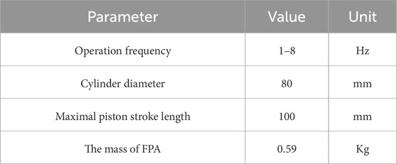
Table 1. The main parameters of the FPE-LG.
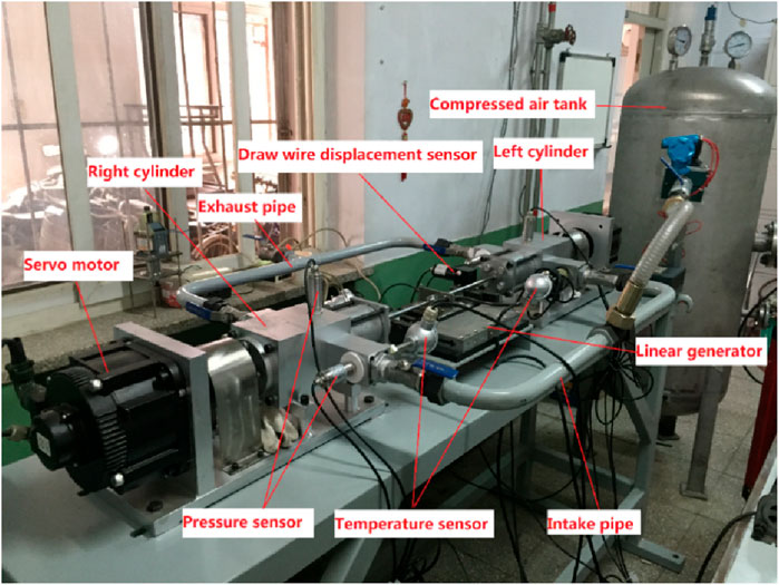
Figure 1. Test rig of FPE-LG.
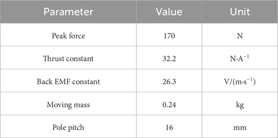
Table 2. The main parameters of the LG.
The definitions of the operational top dead center, operational bottom dead center, and the central equilibrium position of the FPE-LG are consistent with those reported Hou et al. (2017).
2.2 Simulation model of the FPE-LG
A dynamic simulation model of the FPE-LG system is developed in MATLAB/Simulink based on the first law of thermodynamics and coupled electromechanical principles. The model integrates thermodynamic processes within the expansion chamber, mechanical dynamics of the FPA, and electromagnetic generation characteristics, enabling a comprehensive analysis of system behavior under variable operating conditions. A detailed description of the modeling methodology, assumptions, and sub-model formulations can be found in Xu et al. (2018b). The overall simulation framework is illustrated in Figure 2.
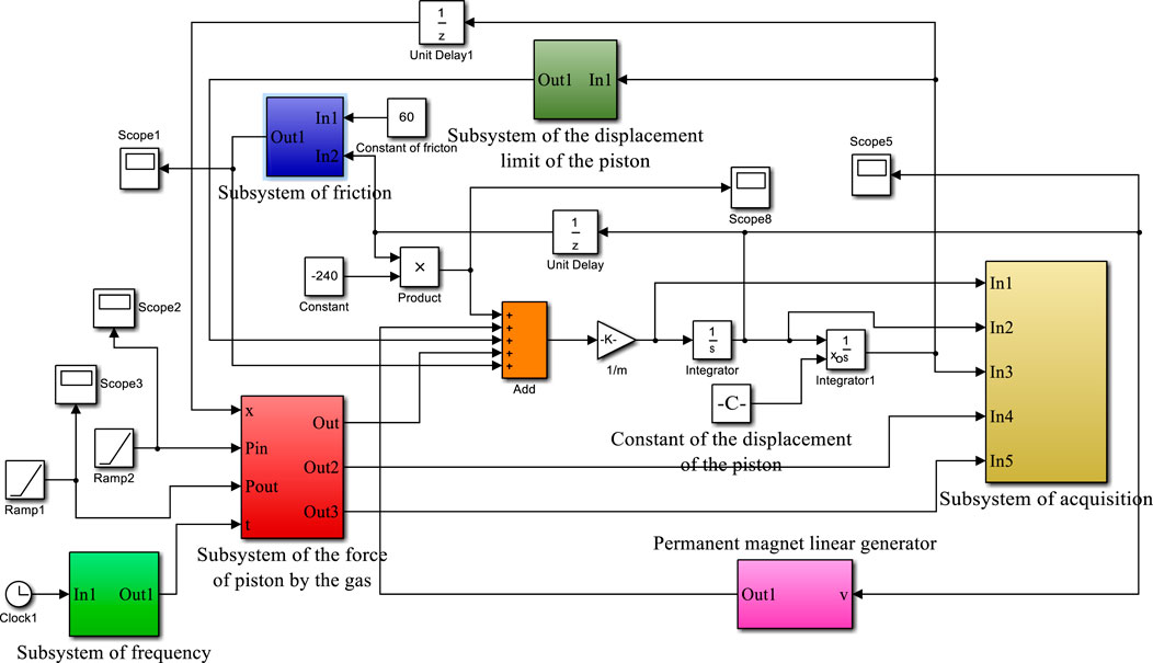
Figure 2. Simulation model of the FPE–LG.
3 Result and discussion
3.1 Effect of the FPA mass on the performance of the FPE-LG
Figure 3 illustrates the velocity–displacement profiles of the FPA under varying FPA masses. As expected, the velocity reaches its maximum near the midpoint of the stroke and drops to zero at the operational top dead center and bottom dead center, consistent with typical reciprocating motion dynamics. A reduction in FPA mass results in increased peak velocity and stroke amplitude, indicating enhanced dynamic responsiveness. To minimize inertial forces and overall moving mass, the FPA is fabricated from a high-strength aluminum alloy. Under the specified operating conditions—intake pressure of 3 bar, operating frequency of 5 Hz, external load resistance of 9 Ω, FPA mass of 0.59 kg, and LG internal resistance of 14.7 Ω—the maximum FPA velocity reaches 3.12 m/s.
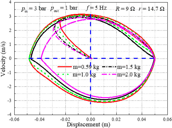
Figure 3. Displacement and the corresponding velocity varies with the different mass of FPA.
The electromagnetic force varies with the mass of the FPA as shown in Figure 4. It is observed that the electromagnetic force shows a downward trend when the mass of the FPA decreases. According to the Ref. (Jia et al., 2016), the electromagnetic force can be written as Equation 1:
where Ce is the electromagnetic resistance coefficient, which is written as Equation 2:
where Kf is the electromagnetic thrust force constant, Kv is the back electromotive force constant, R is the external load resistance, Ls is the inductance of LG, and r is the internal resistance of LG. So, the electromagnetic force and the velocity exhibit the same trend when varies the mass of the FPA.
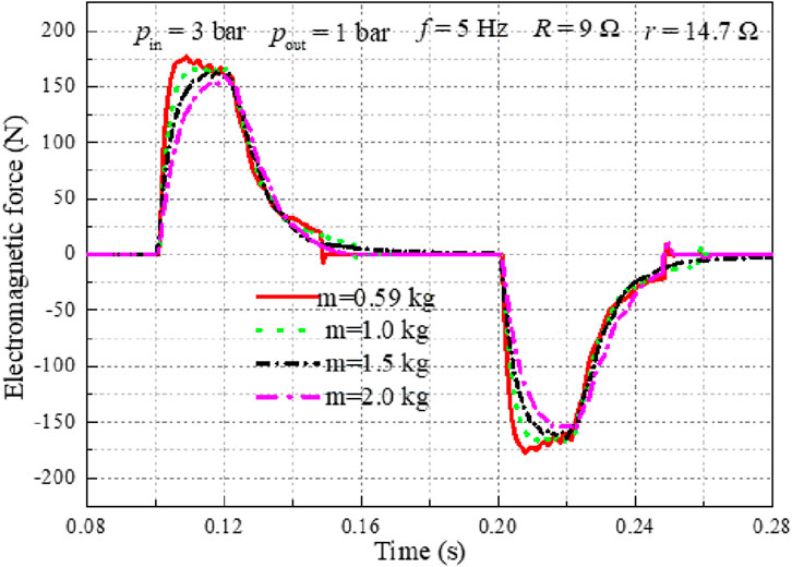
Figure 4. Effect of the FPA’ mass on the electromagnetic force.
Figures 5, 6 illustrate the influence of FPA mass on the voltage output and power output, respectively. The voltage and power output exhibit a similar trend with varying FPA mass, indicating a strong correlation between the two electrical performance metrics under different inertial conditions. The power output is denoted as Equation 3:
where Pout is the power output, U is the effective value of the voltage across the external load resistance. The voltage output and the power output reach the maximum of 30.0 V and 96.0 W when the intake pressure, operation frequency, external load resistance, mass of the FPA, and the internal resistance of LG are 3 bar, 5 Hz, 9 Ω, 0.59 kg and 14.7 Ω, respectively.
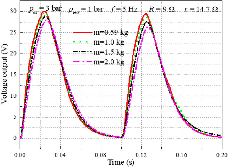
Figure 5. Voltage output varies with the changing mass of the FPA.
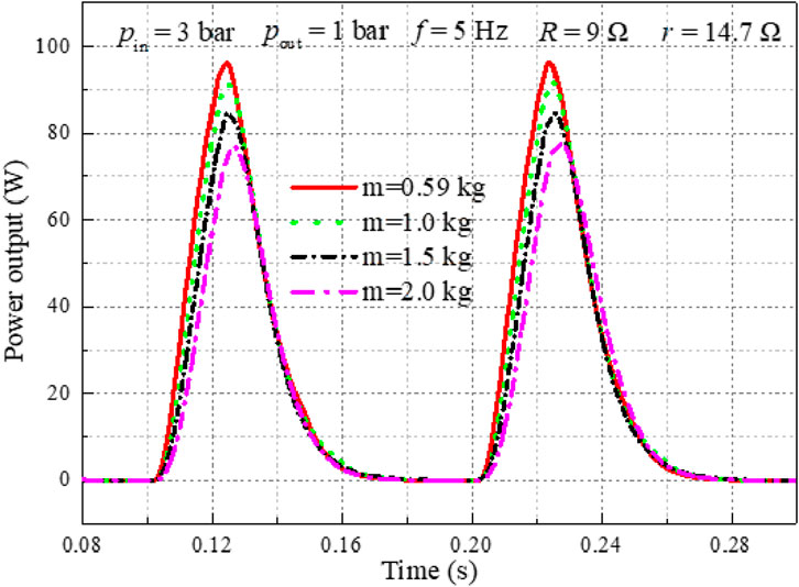
Figure 6. Power output varies with the changing mass of the FPA.
3.2 Effect of the internal resistance of the LG on the performance of the FPE-LG
The dynamic performance of the FPE-LG system is significantly influenced by the characteristics of the LG, particularly its internal resistance. The increase in external load resistance reduces the electromagnetic damping force of the generator, allowing the piston to obtain greater acceleration under the same gas pressure drive, thereby moving to a farther position. As shown in Figure 7, increasing the LG’s internal resistance results in an increase in piston displacement. This behavior can be attributed to the reduced electromagnetic damping effect at higher internal resistance, which diminishes the electrical load on the moving FPA and allows for greater stroke amplitude. Under the following operating conditions—intake pressure of 3 bar, operating frequency of 6 Hz, external load resistance of 9 Ω, FPA mass of 0.59 kg, and LG internal resistance of 20 Ω—the maximum displacement of 0.095 m is achieved.
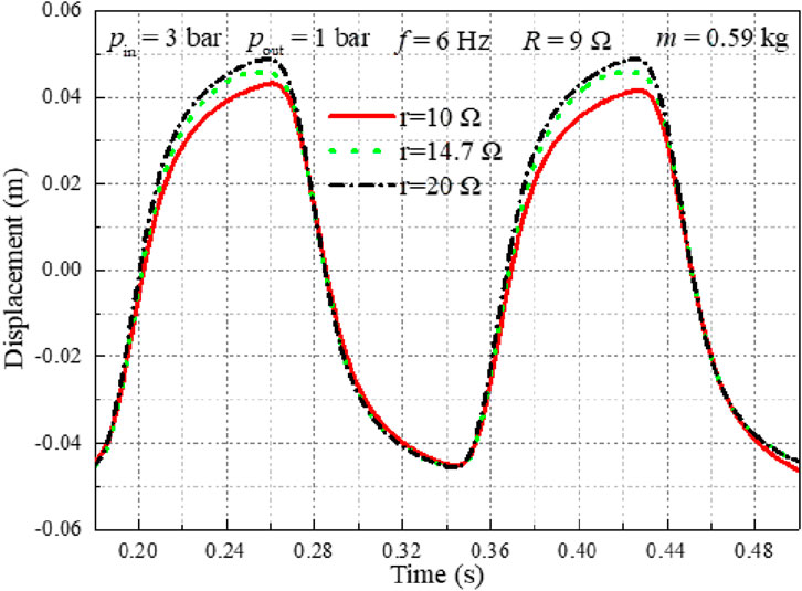
Figure 7. Effect of the internal resistance on the displacement.
Figure 8 illustrates the influence of the internal resistance of LG on the velocity of the FPA. Consistent with the displacement trend observed in Figure 7, the peak piston velocity increases with rising internal resistance. This behavior is attributed to the reduction in electromagnetic force as the internal resistance increases, which weakens the electromagnetic damping effect and allows the FPA to achieve higher acceleration and velocity. Specifically, when the LG internal resistance is increased from 10 Ω to 20 Ω, the peak velocity rises from 2.7 m/s to 3.1 m/s under the specified operating conditions.
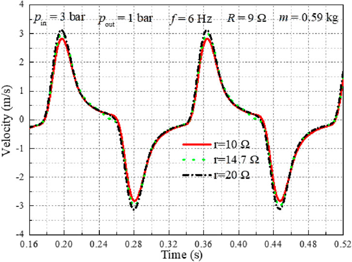
Figure 8. Effect of the internal resistance on the velocity.
Figure 9 presents the variation of electromagnetic force with respect to the internal resistance of the LG. The results demonstrate that the LG’s internal resistance has a significant influence on the magnitude of the electromagnetic force. As the internal resistance increases, the peak electromagnetic force exhibits a pronounced decreasing trend due to the reduced current in the generator coil, consistent with Ohm’s law and the Lorentz force principle. Specifically, when the internal resistance is increased from 10 Ω to 20 Ω, the peak force amplitude decreases from −245.4 N to 229.9 N, reflecting a reduction in electromagnetic damping and load coupling.
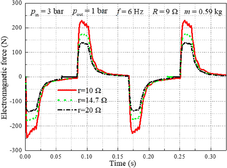
Figure 9. Electromagnetic force variation with the changing internal resistance of LG.
The current output with different internal resistance of LG is exhibited in Figure 10. According to the Ohm’s law, the current is calculated by Equation 4:
where Iout is the current output. The current output is rectified by a rectifier. When the intake pressure, operation frequency, external load resistance, mass of the FPA, and internal resistance of LG are set at 3 bar, 6 Hz, 9 Ω, 0.59 kg, and 10 Ω, respectively, the maximum current recorded is 4.0 A.
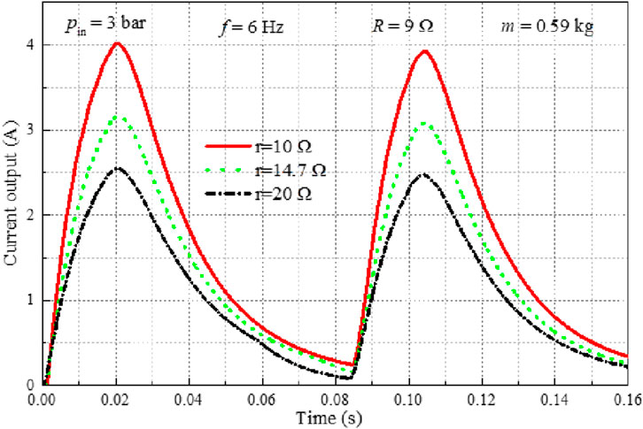
Figure 10. Effect of the internal resistance on the current output.
Figure 11 presents the power output of the FPE-LG system under varying internal resistance of the LG, corresponding to the voltage trends shown in Figure 10. A consistent trend is observed: power output increases as the LG’s internal resistance decreases. This indicates that the internal resistance of the LG exerts a significant influence on the system’s electrical performance. The enhancement in power output at lower internal resistance is attributed to reduced ohmic losses and improved current delivery, thereby increasing the effective power transferred to the load. These results demonstrate that minimizing the LG’s internal resistance is crucial for maximizing the output performance of the FPE-LG system. Under the tested conditions, the peak power output reaches 145.2 W when the internal resistance is reduced to 10 Ω, with an FPA mass of 0.59 kg, intake pressure of 3 bar, operating frequency of 6 Hz, and external load resistance of 9 Ω—representing the optimal configuration identified in this study.

Figure 11. Effect of the internal resistance on the power output.
3.3 Effect of the changing intake pressure on the performance of the FPE-LG
To better align with the operational requirements of the ORC, we have conducted an investigation into the performance of the free piston expander with linear generator (FPE-LG) under varying operating conditions. Figure 12 illustrates the displacement of the free piston assembly (FPA) under four different variable conditions. Figure 12a presents the situation that the intake pressure increases evenly with time. It is clearly that the displacement of FPA in Figure 12a shows an upward trending evenly with time. The displacement of the FPA is depicted in Figure 12b when the intake pressure is reduced evenly with time. The displacement of the FPA is displayed in Figure 12c when the intake pressure suddenly increases at a certain moment. The displacement of the FPA is as shown in Figure 12d when the intake pressure suddenly decreases at a certain moment. It can be seen from Figure 12, the changing of displacement is closely related to the changing of intake pressure.
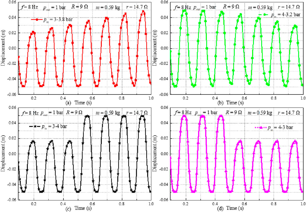
Figure 12. Displacement varies with the changing of the intake pressure, (a) pin = 3-3.8 bar, (b) pin = 4-3.2 bar, (c) pin = 3-4 bar, (d) pin = 4-3 bar.
To evaluate the dynamic response of the free piston expander-linear generator (FPE-LG) under varying operating conditions relevant to ORC applications, the displacement characteristics of the free piston assembly (FPA) were investigated. Figure 12 illustrates the FPA displacement under four distinct intake pressure perturbation scenarios:
As intake pressure increases linearly over time (Figure 12a), the FPA displacement exhibits a corresponding steady upward trend, indicating a direct proportional relationship between pressure input and piston position under quasi-steady conditions. Conversely, a linear decrease in intake pressure (Figure 12b) results in a proportional downward trend in FPA displacement, confirming the inverse relationship observed during pressure reduction. A step increase in intake pressure at a specific time instant (Figure 12c) induces an immediate and significant upward displacement jump in the FPA. This transient response highlights the system’s sensitivity to abrupt pressure changes and its inherent inertia. Similarly, a step decrease in intake pressure (Figure 12d) causes a rapid downward displacement jump, demonstrating the system’s capacity to respond quickly to negative pressure transients. Collectively, the results presented in Figure 12 unequivocally demonstrate that the FPA displacement is directly and dynamically governed by the temporal profile of the intake pressure. The magnitude and rate of displacement change are intrinsically linked to the magnitude and rate of the applied pressure variation, whether gradual or abrupt. This underscores the critical role of intake pressure as the primary driver of FPE-LG motion characteristics under variable operating conditions.
Figure 13 presents the velocity response of the FPA under varying intake pressure conditions. A strong positive correlation is observed between the intake pressure and the FPA velocity: as the intake pressure increases or decreases—whether gradually or abruptly—the peak velocity correspondingly rises or falls. This dynamic behavior indicates that the intake pressure significantly influences the motion characteristics of the FPE-LG system, particularly the piston displacement and velocity, due to its direct impact on the driving force during the expansion process. These results confirm that intake pressure is a dominant parameter governing the system’s dynamic performance.
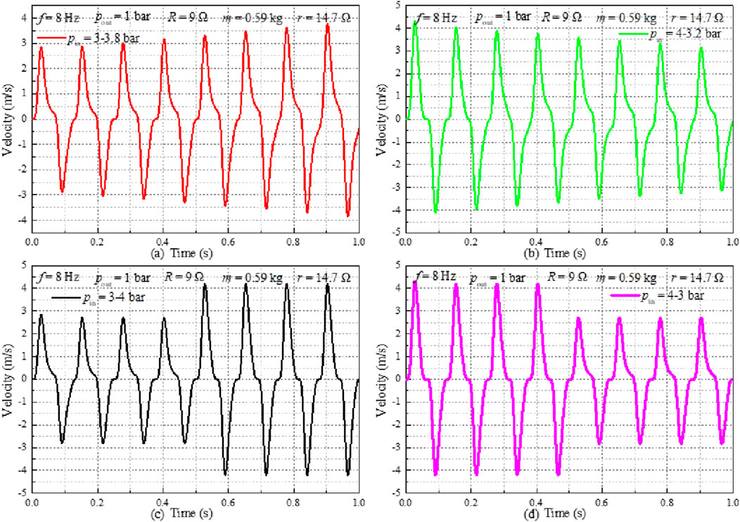
Figure 13. Velocity varies with the changing of the intake pressure, (a) pin = 3-3.8 bar, (b) pin = 4-3.2 bar, (c) pin = 3-4 bar, (d) pin = 4-3 bar.
Figure 14 illustrates the variation of electromagnetic force with changing intake pressure. According to Equation 1, the electromagnetic force is directly proportional to the velocity of the FPA. As the intake pressure increases, the resulting higher piston velocity leads to a greater induced electromotive force and, consequently, an increase in electromagnetic force. It is evident from Figure 14 that the electromagnetic force exhibits a consistent trend with the intake pressure, rising and falling in response to pressure variations—further confirming the strong coupling between the mechanical dynamics and electromagnetic output of the FPE-LG system.
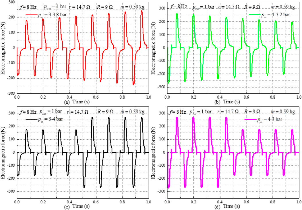
Figure 14. Variation of the electromagnetic force with the changing intake pressure, (a) pin = 3-3.8 bar, (b) pin = 4-3.2 bar, (c) pin = 3-4 bar, (d) pin = 4-3 bar.
Figure 15 presents the voltage output of the FPE-LG system under varying intake pressure conditions. The voltage exhibits a consistent trend with the intake pressure, increasing during pressure rise and decreasing during pressure drop, which reflects the strong dependence of electrical output on the piston velocity and electromagnetic force. This behavior further demonstrates that the intake pressure significantly influences the overall output performance of the FPE-LG system, particularly the voltage, current, and power output, due to its direct impact on the mechanical dynamics and electromotive force generation. These results highlight the critical role of intake pressure regulation in optimizing system performance under transient operating conditions. Figure 16 presents the power output of the FPE-LG system under varying intake pressure conditions. The variation trend of power output under varying intake pressure conditions is basically consistent with the variation trend of voltage output.
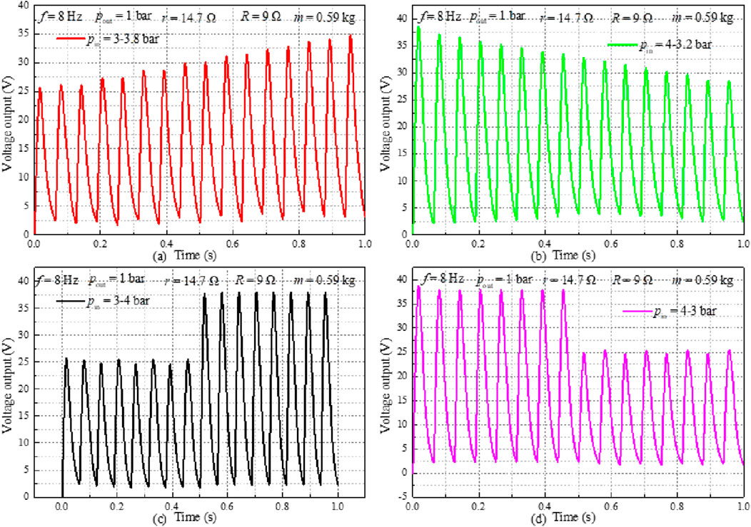
Figure 15. The variation of the voltage output with the changing intake pressure, (a) pin = 3-3.8 bar, (b) pin = 4-3.2 bar, (c) pin = 3-4 bar, (d) pin = 4-3 bar.
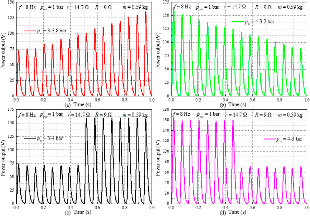
Figure 16. Variation of the power output with the changing intake pressure, (a) pin = 3-3.8 bar, (b) pin = 4-3.2 bar, (c) pin = 3-4 bar, (d) pin = 4-3 bar.
3.4 Effect of the changing exhaust pressure on the performance of the FPE-LG
The performance of the free-piston expander with linear generator (FPE-LG) is influenced not only by the intake conditions but also critically by the exhaust back pressure, which affects the net pressure differential across the piston and thus the expansion work. Figure 17a illustrates the effect of exhaust back pressure on the FPA displacement under constant operating conditions. When the exhaust back pressure is 1.0 bar, the peak displacement reaches 0.087 m; however, it decreases to 0.076 m as the back pressure increases to 1.2 bar, indicating a reduction in effective stroke due to diminished pressure differential. Figures 17b,c further demonstrate the dynamic response of the system under transient back pressure conditions. Under a gradually increasing back pressure, the displacement exhibits a downward trend (Figure 17b), while a decreasing back pressure results in a corresponding increase in displacement (Figure 17c). These results confirm that the FPE-LG system is highly sensitive to exhaust back pressure variations, and maintaining an optimal back pressure is essential for maximizing stroke length and, consequently, power output.

Figure 17. Effect of exhaust back pressure on the displacement of the FPA, (a) pout = 1,2 bar, (b) pout = 1-1.3 bar, (c) pout = 1.3-1 bar.
Figure 18 illustrates the influence of exhaust back pressure on the velocity of the FPA. The peak velocity reaches 3.8 m/s at an exhaust back pressure of 1.0 bar, decreasing to 3.45 m/s when the back pressure is increased to 1.2 bar. This reduction is attributed to the diminished net pressure differential across the piston, which lowers the driving force and consequently limits the piston’s acceleration and maximum speed. Consistent with the displacement trends shown in Figure 17, the velocity exhibits a similar dynamic response under time-varying back pressure conditions: a gradual increase in back pressure leads to a decreasing velocity trend (Figure 18b), while a decreasing back pressure results in a corresponding rise in velocity (Figure 18c). These results further confirm the strong sensitivity of the FPE-LG system’s dynamic behavior to exhaust back pressure, highlighting its critical role in determining both stroke and speed performance.
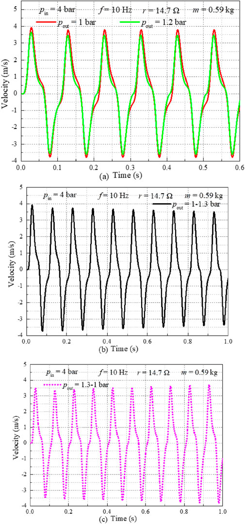
Figure 18. Effect of exhaust back pressure on the velocity of the FPA, (a) pout = 1,2 bar, (b) pout = 1-1.3 bar, (c) pout = 1.3-1 bar.
Figure 19 presents the variation of electromagnetic force with changing exhaust back pressure in the FPE-LG system. As shown in Figure 19a, the peak electromagnetic force is significantly higher under an exhaust back pressure of 1.0 bar compared to 1.2 bar, demonstrating the sensitivity of the electrical output to exhaust conditions. This behavior is attributed to the greater piston velocity achieved at lower back pressure, which enhances the induced electromotive force and current generation in the LG. Further analysis in Figures 19b,c reveals a clear inverse relationship between exhaust back pressure and electromagnetic force. When the back pressure increases gradually, the electromagnetic force exhibits a decreasing trend (Figure 19b), while a reduction in back pressure results in a corresponding increase in electromagnetic force (Figure 19c). These dynamic responses confirm that the exhaust back pressure directly influences the mechanical-to-electrical energy conversion efficiency by modulating the piston’s kinetic energy and, consequently, the electromagnetic output.
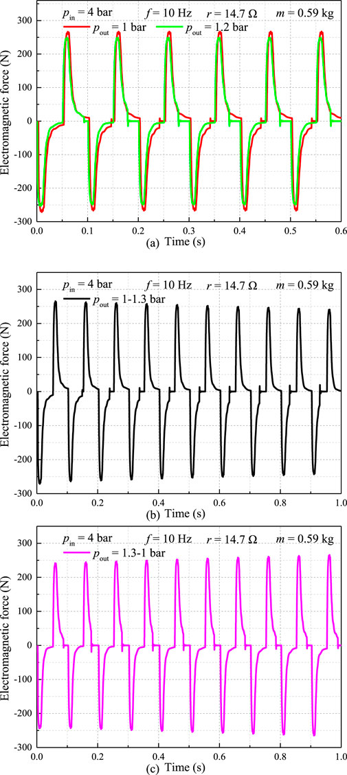
Figure 19. Effect of exhaust back pressure on the electromagnetic force of the LG, (a) pout = 1,2 bar, (b) pout = 1-1.3 bar, (c) pout = 1.3-1 bar.
Figure 20a presents the voltage output of the FPE-LG system under different exhaust back pressure conditions. At a back pressure of 1.0 bar, the voltage ranges from 6.2 V to 34.8 V, whereas it decreases to a range of 4.2 V–32.2 V when the back pressure increases to 1.2 bar. This reduction in both minimum and peak voltage reflects the diminished piston velocity and lower rate of change of magnetic flux linkage, resulting from the reduced net pressure differential across the piston. Figures 20b,c further illustrate the dynamic response of the voltage output to transient back pressure variations. Under gradually increasing back pressure, the voltage exhibits a clear downward trend (Figure 20b), while a decreasing back pressure leads to a corresponding recovery and increase in voltage amplitude (Figure 20c). These results demonstrate that the electrical output of the FPE-LG is highly sensitive to exhaust back pressure, with lower back pressure enabling higher electromotive force generation and improved energy conversion performance.
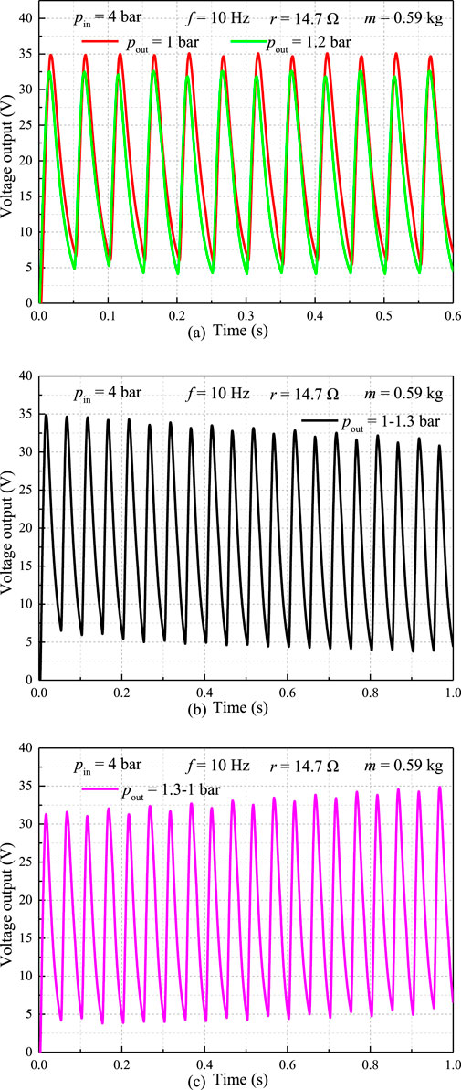
Figure 20. Variation of the voltage output with the changing exhaust back pressure, (a) pout = 1,2 bar, (b) pout = 1-1.3 bar, (c) pout = 1.3-1 bar.
Figure 21 illustrates the influence of exhaust back pressure on the power output of the FPE-LG system, complementing the voltage trends presented in Figure 20. Under steady operating conditions, the peak power output reaches 136.0 W at an exhaust back pressure of 1.0 bar, decreasing to 118.2 W when the back pressure is increased to 1.2 bar (Figure 21a). This 13.1% reduction in peak power underscores the significant impact of back pressure on the system’s energy conversion efficiency. The power output exhibits a strong correlation with the exhaust back pressure, mirroring the trends observed in both voltage and piston velocity. This consistency confirms that the electrical performance of the FPE-LG is critically dependent on the mechanical dynamics, which are governed by the net pressure differential across the piston. Lower back pressure enhances the expansion work, leading to higher piston velocity, greater electromagnetic force, and consequently improved power generation.
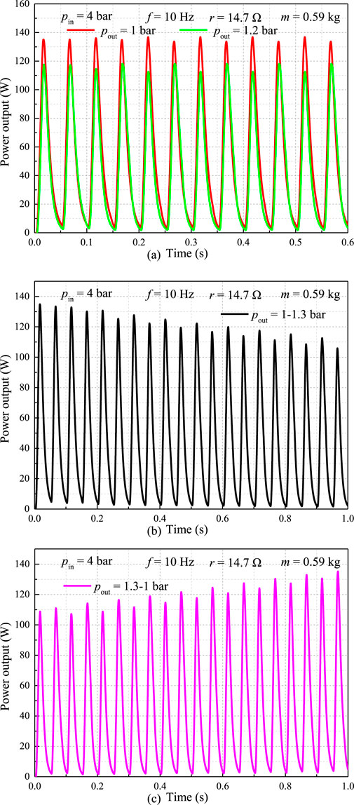
Figure 21. Effect of the changing exhaust back pressure on the power output, (a) pout = 1,2 bar, (b) pout = 1-1.3 bar, (c) pout = 1.3-1 bar.
3.5 Effect of the changing intake and the exhaust pressure on the performance of the FPE-LG
The expansion ratio has an important influence on the performance of the FPE-LG. According to Ref. [41], the expansion ratio is calculated by Equation 5:
where the ε is the expansion ratio, the pin and pout are the intake pressure and the exhaust back pressure of the FPE, respectively.
The displacement variation under changing intake pressure and exhaust back pressure is presented in Figure 22. Compared to the displacement in Figure 12a, the displacement in Figure 22a exhibits less variation. This behavior occurs because an increase in intake pressure is accompanied by a corresponding increase in exhaust back pressure. In contrast to the displacement trend observed in Figure 17b, the displacement in Figure 22a demonstrates an opposite trend over time. This discrepancy arises because the exhaust pressure increase is coupled with an intake pressure increase, where the rate of intake pressure rise over time exceeds that of the exhaust back pressure. Figure 22b illustrates the displacement variation over time when intake pressure and exhaust pressure vary at identical rates. The results in Figure 22b indicate that the peak displacement value remains nearly constant over time. Conversely, the displacement in Figure 22c displays a decreasing trend, attributed to the exhaust back pressure increasing at a higher rate over time than the intake pressure. Finally, compared to the displacement in Figure 12a, the peak displacement value in Figure 22d exhibits significant temporal variation.
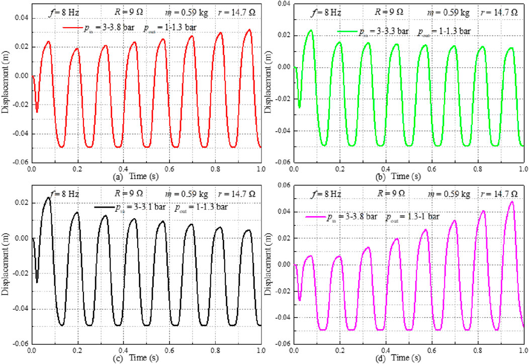
Figure 22. Effect of the changing intake pressure and exhaust back pressure on the displacement, (a) pin = 3-3.8 bar, pout = 1.3-1 bar, (b) pin = 3-3.3 bar, pout = 1.3-1 bar, (c) pin = 3-3.1 bar, pout = 1.3-1 bar, (d) pin = 3-3.8 bar, pout = 1.3-1 bar.
The variation in Free Piston Assembly (FPA) velocity with changing intake pressure and exhaust back pressure is presented in Figure 23. In Figure 23a, despite the exhaust back pressure increasing from 1 bar to 1.3 bar, the FPA velocity exhibits an upward trend. This behavior is attributed to the concurrent increase in intake pressure from 3 bar to 3.8 bar. Similar to the observation in Figure 22b, the FPA velocity in Figure 23b demonstrates minimal variation when both intake pressure and exhaust back pressure increase at the same rate. The results in Figure 23c indicate that exhaust back pressure exerts a dominant influence on velocity when its rate of increase exceeds that of intake pressure. Furthermore, the FPA velocity in Figure 23d exhibits significantly greater temporal variation compared to that observed in Figure 23a.
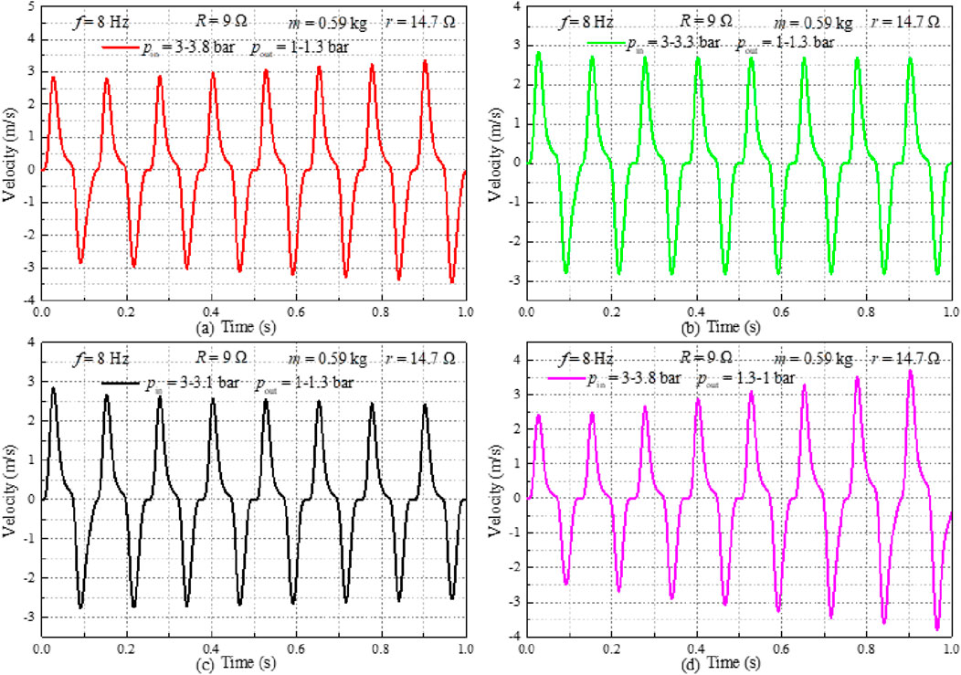
Figure 23. Effect of the changing intake pressure and exhaust back pressure on the velocity, (a) pin = 3-3.8 bar, pout = 1.3-1 bar, (b) pin = 3-3.3 bar, pout = 1.3-1 bar, (c) pin = 3-3.1 bar, pout = 1.3-1 bar, (d) pin = 3-3.8 bar, pout = 1.3-1 bar.
The influence of varying intake pressure and exhaust back pressure on the electromagnetic force is presented in Figure 24. The results demonstrate that the electromagnetic force is directly correlated with changes in the Free Piston Assembly (FPA) velocity induced by these pressure variations. An increasing trend in electromagnetic force is observed when the rate of increase in intake pressure exceeds that of exhaust back pressure (Figure 24a). Conversely, when intake pressure and exhaust back pressure increase at similar rates, their effects on the electromagnetic force are comparable (Figure 24b). Specifically, increasing exhaust back pressure from 1 bar to 1.3 bar while increasing intake pressure from 3 bar to 3.1 bar results in a downward trend in electromagnetic force (Figure 24c). Furthermore, increasing intake pressure while reducing exhaust back pressure enhances FPA motion, leading to a significant upward trend in electromagnetic force under these conditions (Figure 24d).
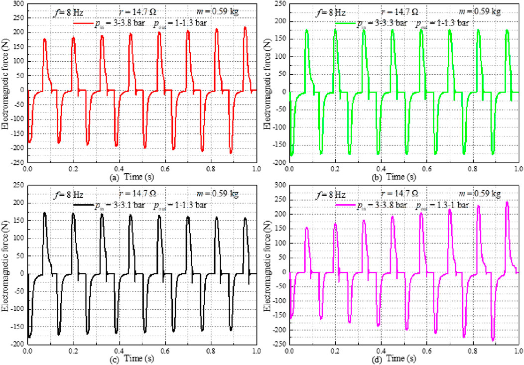
Figure 24. Variation of the electromagnetic force with the changing intake pressure and exhaust back pressure, (a) pin = 3-3.8 bar, pout = 1.3-1 bar, (b) pin = 3-3.3 bar, pout = 1.3-1 bar, (c) pin = 3-3.1 bar, pout = 1.3-1 bar, (d) pin = 3-3.8 bar, pout = 1.3-1 bar.
The influence of varying intake pressure and exhaust back pressure on voltage output is presented in Figure 25. As shown in Figure 25a, the peak voltage output exhibits an increasing trend when intake pressure rises from 3 bar to 3.8 bar while exhaust back pressure increases from 1 bar to 1.3 bar. Notably, the peak voltage output displays asymmetric fluctuations between high and low values. This phenomenon is attributed to the inconsistency between the magnitudes of the peak forward velocity and peak negative velocity. Minor fluctuations in peak output voltage are observed in Figure 25b when intake pressure and exhaust back pressure increase at identical rates. Conversely, Figure 25c demonstrates a decreasing trend in peak voltage output when the rate of increase in exhaust back pressure exceeds that of intake pressure. It is established that increasing intake pressure while reducing exhaust back pressure enhances voltage output. Under these conditions, Figure 25d reveals that the peak voltage output exhibits a predominantly linear trend over time.
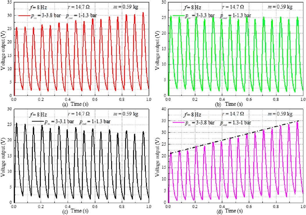
Figure 25. Variation of the voltage output with the changing intake pressure and exhaust back pressure, (a) pin = 3-3.8 bar, pout = 1.3-1 bar, (b) pin = 3-3.3 bar, pout = 1.3-1 bar, (c) pin = 3-3.1 bar, pout = 1.3-1 bar, (d) pin = 3-3.8 bar, pout = 1.3-1 bar.
Figure 26 illustrates the variation in power output under changing intake pressure and exhaust back pressure conditions. As depicted in Figure 26a, the power output exhibits a linear temporal trend when both intake pressure and exhaust back pressure increase simultaneously. Figure 26b reveals slight fluctuations in power output when intake pressure and exhaust back pressure increase at identical rates. Conversely, Figure 26c demonstrates a decreasing trend when the rate of increase in exhaust back pressure exceeds that of intake pressure over time. Notably, the temporal rate of change in peak power output observed in Figure 26d is significantly greater than that in Figure 26a. These results indicate that increasing intake pressure while reducing exhaust back pressure constitutes an effective strategy for enhancing the performance of the Free-Piston Engine-Linear Generator (FPE-LG).
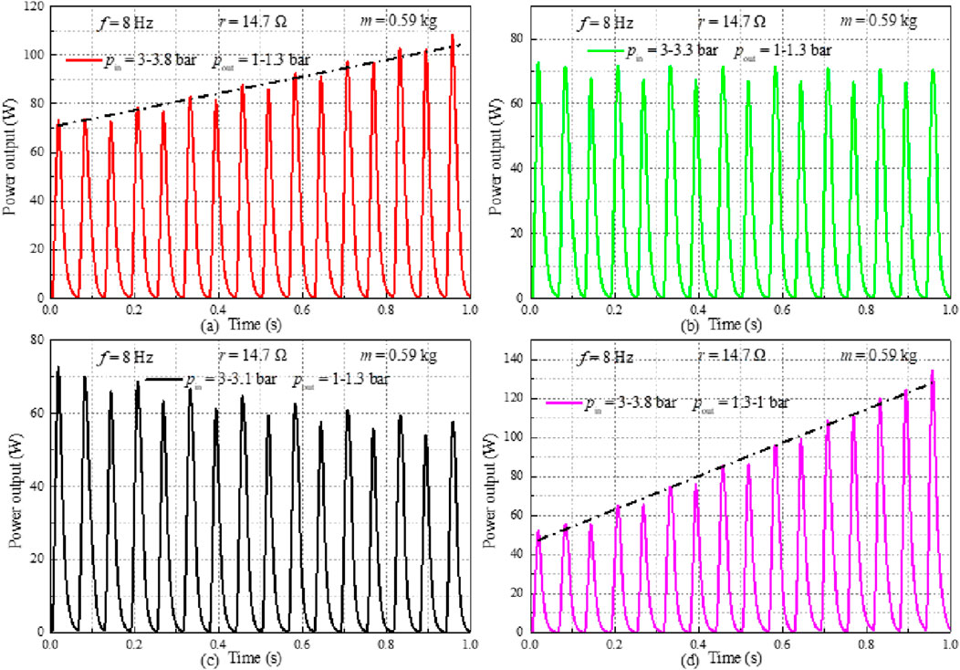
Figure 26. Variation of the power output with the changing intake pressure and exhaust back pressure, (a) pin = 3-3.8 bar, pout = 1.3-1 bar, (b) pin = 3-3.3 bar, pout = 1.3-1 bar, (c) pin = 3-3.1 bar, pout = 1.3-1 bar, (d) pin = 3-3.8 bar, pout = 1.3-1 bar.
4 Conclusion
This study presents a comprehensive dynamic model of a free piston expander coupled with a linear generator in an ORC system, enabling performance optimization through key parameter analysis. The core innovation lies in systematically quantifying the coupled effects of mechanical design (piston mass) and electrical configuration (generator internal resistance) on system output.
Results demonstrate that reducing piston mass and generator internal resistance significantly enhances power output, with a maximum of 145.2 W achieved under optimized conditions. Furthermore, performance is highly sensitive to intake and exhaust pressures, confirming that higher pressure differentials dramatically improve piston motion and electrical output. This work provides a validated modeling framework and clear design guidelines for maximizing FPE-LG efficiency.
The future research work is likely to be an iterative process: to explore and optimize the most matching combination of FPE-LG and working fluid for the application needs of a specific type of vehicle, so as to develop products with both progressiveness technology and commercial feasibility.
Data availability statement
The raw data supporting the conclusions of this article will be made available by the authors, without undue reservation.
Author contributions
DY: Conceptualization, Funding acquisition, Investigation, Writing – original draft. LL: Methodology, Software, Supervision, Writing – review and editing. ZD: Methodology, Supervision, Validation, Writing – review and editing. JZ: Methodology, Validation, Writing – review and editing. YX: Funding acquisition, Software, Writing – review and editing.
Funding
The authors declare that financial support was received for the research and/or publication of this article. This work was sponsored by the P&D Program of Beijing Municipal Education Commission (KM202410858004) and New Energy Automobile Motor Industry Technology Development Base (Grant Nos. 2025K01 and 2025K02).
Acknowledgments
AcknowledgementsThe authors would like to thank the editors and reviewers for their valuable comments on this research.
Conflict of interest
The authors declare that the research was conducted in the absence of any commercial or financial relationships that could be construed as a potential conflict of interest.
Generative AI statement
The authors declare that no Generative AI was used in the creation of this manuscript.
Any alternative text (alt text) provided alongside figures in this article has been generated by Frontiers with the support of artificial intelligence and reasonable efforts have been made to ensure accuracy, including review by the authors wherever possible. If you identify any issues, please contact us.
Publisher’s note
All claims expressed in this article are solely those of the authors and do not necessarily represent those of their affiliated organizations, or those of the publisher, the editors and the reviewers. Any product that may be evaluated in this article, or claim that may be made by its manufacturer, is not guaranteed or endorsed by the publisher.
Abbreviations
ORC, organic Rankine cycle; LG, linear generator; ICEs, internal combustion engines; PID, proportion integral differential; ANN, artificial neural network; FPE-LG, free piston expander-linear generator; FPE, free piston expander; PMLG, permanent magnet linear generator; FPA, free piston assembly; OTDC, operation top dead center; OBDC, operation bottom dead center; EMF, back electromotive force.
References
Antonelli, M., Baccioli, A., Francesconi, M., Desideri, U., and Martorano, L. (2014). Operating maps of a rotary engine used as an expander for micro-generation with various working fluids. Appl. Energy 113, 742–750. doi:10.1016/j.apenergy.2013.08.003
Aziz, A. R. A., Ismael, M. A., Mohammed, S. E., Baharom, M. B., and Anwarudin, A. (2022). Effect of generator configuration on the free-piston motion and power generation of air-driven expander system. Alexandria Eng. J. 61 (4), 3093–3104. doi:10.1016/j.aej.2021.08.038
Bianchi, M., Branchini, L., De Pascale, A., Melino, F., Ottaviano, S., Peretto, A., et al. (2019). Application and comparison of semi-empirical models for performance prediction of a kW-size reciprocating piston expander. Appl. Energy 249, 143–156. doi:10.1016/j.apenergy.2019.04.070
Burugupally, S. P., and Weiss, L. (2019). Design and performance of a miniature free piston expander. Energy 170, 611–618. doi:10.1016/j.energy.2018.12.158
Burugupally, S. P., Weiss, L., and Depcik, C. (2019). The effect of working fluid properties on the performance of a miniature free piston expander for waste heat harvesting. Appl. Therm. Eng. 151, 431–438. doi:10.1016/j.applthermaleng.2019.02.035
Feng, Y. Q., Hung, T. C., He, Y. L., Wang, Q., Chen, S. C., Wu, S. L., et al. (2019). Experimental investigation of lubricant oil on a 3 kW organic Rankine cycle (ORC) using R123. Energy Convers. Manag. 182, 340–350. doi:10.1016/j.enconman.2018.12.021
Galindo, J., Ruiz, S., Dolz, V., Royo-Pascual, L., Haller, R., Nicolas, B., et al. (2015). Experimental and thermodynamic analysis of a bottoming organic Rankine cycle (ORC) of gasoline engine using swash-plate expander. Energy Convers. Manag. 103, 519–532. doi:10.1016/j.enconman.2015.06.085
Galindo, J., Dolz, V., Royo-Pascual, L., Haller, R., and Melis, J. (2016). Modeling and experimental validation of a volumetric expander suitable for waste heat recovery from an automotive internal combustion engine using an organic rankine cycle with ethanol. Energies 9 (4), 279. doi:10.3390/en9040279
Gao, J., Ma, C., Tian, G., Xing, S., and Jenner, P. (2021). Numerical investigations of an opposed rotary piston expander for the purpose of the applications to a small-scale rankine cycle. Appl. Therm. Eng. 182, 116157. doi:10.1016/j.applthermaleng.2020.116157
Garg, P., Karthik, G. M., Kumar, P., and Kumar, P. (2016). Development of a generic tool to design scroll expanders for ORC applications. Appl. Therm. Eng. 109, 878–888. doi:10.1016/j.applthermaleng.2016.06.047
Hou, X. C., Zhang, H. G., Yu, F., Liu, H. D., Yang, F. B., Xu, Y. H., et al. (2017). Free piston expander-linear generator used for organic rankine cycle waste heat recovery system. Appl. Energy 208, 1297–1307. doi:10.1016/j.apenergy.2017.09.024
Hou, X. C., Zhang, H. G., Xu, Y. H., Yu, F., Zhao, T. L., Tian, Y. M., et al. (2018). External load resistance effect on the free piston expander-linear generator for organic rankine cycle waste heat recovery system. Appl. Energy 212, 1252–1261. doi:10.1016/j.apenergy.2018.01.020
Jia, B. R., Smallbone, A., Zuo, Z. X., and Roskilly, A. P. (2016). Design and simulation of a two-or four-stroke free-piston engine generator for range extender applications. Energy Convers. Manag. 111, 289–298. doi:10.1016/j.enconman.2015.12.063
Jia, B. R., Mikalsen, R., Smallbone, A., and Roskilly, A. P. (2018). A study and comparison of frictional losses in free-piston engine and crankshaft engines. Appl. Therm. Eng. 140, 217–224. doi:10.1016/j.applthermaleng.2018.05.018
Kanno, H., and Shikazono, N. (2016). Experimental study on two-phase adiabatic expansion in a reciprocating expander with intake and exhaust processes. Int. J. Heat Mass Transf. 102, 1004–1011. doi:10.1016/j.ijheatmasstransfer.2016.06.081
Li, J., Zhang, H., Tian, Y. M., Hou, X. C., Xu, Y. H., Zhao, T. L., et al. (2019). Performance analysis of a single-piston free piston expander-linear generator with intake timing control strategy based on piston displacement. Appl. Therm. Eng. 152, 751–761. doi:10.1016/j.applthermaleng.2019.02.121
Li, J., Yang, F., Zhang, H., Wu, Z., Tian, Y., Hou, X., et al. (2020). Comparative analysis of different valve timing control methods for single-piston free piston expander-linear generator via an orthogonal experimental design. Energy 195, 116966. doi:10.1016/j.energy.2020.116966
Linnemann, M., Priebe, K. P., Herres, G., Wolff, C., and Vrabec, J. (2019). Design and test of a multi-coil helical evaporator for a high temperature organic rankine cycle plant driven by biogas waste heat. Energy Convers. Manag. 195, 1402–1414. doi:10.1016/j.enconman.2019.05.053
Luo, X. L., Wang, Y. P., Liang, J. W., Qi, J., Su, W., Yang, Z., et al. (2019). Improved correlations for working fluid properties prediction and their application in performance evaluation of sub-critical organic rankine cycle. Energy 174, 122–137. doi:10.1016/j.energy.2019.02.124
Mendoza, L. C., Navarro-Esbrí, J., Bruno, J. C., Lemort, V., and Coronas, A. (2014). Characterization and modeling of a scroll expander with air and ammonia as working fluid. Appl. Therm. Eng. 70 (1), 630–640. doi:10.1016/j.applthermaleng.2014.05.069
Mikalsen, R., and Roskilly, A. P. (2007). A review of free-piston engine history and applications. Appl. Therm. Eng. 27 (14-15), 2339–2352. doi:10.1016/j.applthermaleng.2007.03.015
Mikalsen, R., and Roskilly, A. P. (2008). The design and simulation of a two-stroke free piston compression ignition engine for electrical power generation. Appl. Therm. Eng. 28 (5), 589–600. doi:10.1016/j.applthermaleng.2007.04.009
Mikalsen, R., and Roskilly, A. P. (2010). The control of a free-piston engine generator. Part 2: engine dynamics and piston motion control. Appl. Energy 87 (4), 1281–1287. doi:10.1016/j.apenergy.2009.06.035
Peng, B., Zhang, K., Guo, C., Tong, L., and Wang, P. (2023). Experimental study on charging performance of free piston expander-linear generator coupled lithium battery system. J. Energy Storage 72, 108735. doi:10.1016/j.est.2023.108735
Quoilin, S., Lemort, V., and Lebrun, J. (2010). Experimental study and modeling of an organic rankine cycle using scroll expander. Appl. Energy 87 (4), 1260–1268. doi:10.1016/j.apenergy.2009.06.026
Shi, X., Hou, X., Yang, F., Zhang, H., Shi, Z., Zhao, T., et al. (2021). Analysis on operation characteristic and output performance of free piston expander-linear generator based on displacement control strategy. Appl. Therm. Eng. 182, 116146. doi:10.1016/j.applthermaleng.2020.116146
Song, P. P., Wei, M. S., Shi, L., Danish, S. N., and Ma, C. C. (2015). A review of scroll expanders for organic rankine cycle systems. Appl. Therm. Eng. 75, 54–64. doi:10.1016/j.applthermaleng.2014.05.094
Sun, J., Liu, Q., and Duan, Y. Y. (2018). Effects of evaporator pinch point temperature difference on thermo-economic performance of geothermal organic rankine cycle systems. Geothermics 75, 249–258. doi:10.1016/j.geothermics.2018.06.001
Wang, E. H., Zhang, H. G., Fan, B. Y., Ouyang, M. G., Zhao, Y., and Mu, Q. H. (2011). Study of working fluid selection of organic rankine cycle (ORC) for engine waste heat recovery. Energy 36 (5), 3406–3418. doi:10.1016/j.energy.2011.03.041
Wu, Z., Zhang, H., Liu, Z., Hou, X., Li, J., Yang, F., et al. (2021). Experimental study on the performance of single-piston free-piston expander—linear generator. Energy 221, 119724. doi:10.1016/j.energy.2020.119724
Xu, Y. H., Tong, L., Zhang, H. G., Hou, X. C., Yang, F. B., Yu, F., et al. (2018a). Experimental investigation of a free piston expander-linear generator with different valve timings. Appl. Therm. Eng. 142, 555–565. doi:10.1016/j.applthermaleng.2018.07.050
Xu, Y. H., Tong, L., Zhang, H. G., Hou, X. C., Yang, F. B., Yu, F., et al. (2018b). Experimental and simulation study of a free piston expander–linear generator for small-scale organic rankine cycle. Energy 161, 776–791. doi:10.1016/j.energy.2018.07.171
Xu, Y. H., Zhang, H. G., Yang, F. B., Tong, L., Yang, Y. F., Yan, D., et al. (2021). Experimental study on small power generation energy storage device based on pneumatic motor and compressed air. Energy Convers. Manag. 234, 113949. doi:10.1016/j.enconman.2021.113949
Yang, F. B., Cho, H. J., Zhang, H. G., Zhang, J., and Wu, Y. T. (2018a). Artificial neural network (ANN) based prediction and optimization of an organic rankine cycle (ORC) for diesel engine waste heat recovery. Energy Convers. Manag. 164, 15–26. doi:10.1016/j.enconman.2018.02.062
Yang, Y. X., Zhang, H. G., Xu, Y. H., Zhao, R., Hou, X. C., and Liu, Y. (2018b). Experimental study and performance analysis of a hydraulic diaphragm metering pump used in organic rankine cycle system. Appl. Therm. Eng. 132, 605–612. doi:10.1016/j.applthermaleng.2018.01.001
Yang, F. B., Zhang, H. G., Hou, X. C., Tian, Y. M., and Xu, Y. H. (2019). Experimental study and artificial neural network based prediction of a free piston expander-linear generator for small scale organic rankine cycle. Energy 175, 630–644. doi:10.1016/j.energy.2019.03.099
Yu, H., Xu, Z., Zhang, Q., Liu, L., and Hua, R. (2019). Two-stroke thermodynamic cycle optimization of a single-cylinder free-piston engine generator. Adv. Mater. Sci. Eng. 2019, 1–11. doi:10.1155/2019/9783246
Yu, X. L., Jiang, R. C., Li, Z., Qian, G., Wang, B. Z., Wang, L., et al. (2023). Synergistic improvement of melting rate and heat storage capacity by a rotation-based method for shell-and-tube latent thermal energy storage. Appl. Therm. Eng. 219, 119480. doi:10.1016/j.applthermaleng.2022.119480
Yuan, C. H., Liu, Y., Han, C. J., and He, Y. T. (2019). An investigation of mixture formation characteristics of a free-piston gasoline engine with direct-injection. Energy 173, 626–636. doi:10.1016/j.energy.2019.02.063
Zheng, N., Zhao, L., Wang, X. D., and Tan, Y. T. (2013). Experimental verification of a rolling-piston expander that applied for low-temperature organic rankine cycle. Appl. Energy 112, 1265–1274. doi:10.1016/j.apenergy.2012.12.030
Glossary
pin intake pressure (bar)
pout exhaust back pressure (bar)
f operation frequency (Hz)
r internal resistance of linear generator (Ω)
R external load resistance (Ω)
m mass (kg)
Fmag electromagnetic force
Ce electromagnetic resistance coefficient
Kv back electromotive force
Kf electromagnetic thrust force constant
Ls inductance of LG
Iout current output
ε expansion ratio
Keywords: organic rankine cycle, free piston expander-linear generator, motion characteristics, variable operation conditions, output performance
Citation: Yan D, Lai L, Deng Z, Zhang J and Xu Y (2025) Dynamic performance of a free piston expander-linear generator for small-scale organic rankine cycle under variable operating conditions: an experimental and numerical investigation. Front. Energy Res. 13:1717162. doi: 10.3389/fenrg.2025.1717162
Received: 01 October 2025; Accepted: 11 November 2025;
Published: 28 November 2025.
Edited by:
Chu Wang, Xi’an Technological University, ChinaReviewed by:
Tan Wu, Zhengzhou University of Light Industry, ChinaDequan Zeng, East China Jiaotong University, China
Copyright © 2025 Yan, Lai, Deng, Zhang and Xu. This is an open-access article distributed under the terms of the Creative Commons Attribution License (CC BY). The use, distribution or reproduction in other forums is permitted, provided the original author(s) and the copyright owner(s) are credited and that the original publication in this journal is cited, in accordance with accepted academic practice. No use, distribution or reproduction is permitted which does not comply with these terms.
*Correspondence: Lianfeng Lai, bGFpbGlhbmZlbmdAbmRudS5lZHUuY24=; Zhihui Deng, VDIzMDRAbmRudS5lZHUuY24=