 Andrew J. Fleming
 Yik Ren Teo
 Kam K. Leang
- 1School of Electrical Engineering and Computer Science, The University of Newcastle, Callaghan, NSW, Australia
- 2Department of Mechanical Engineering, University of Utah, Salt Lake City, UT, USA
This article describes an improvement to integral resonance damping control (IRC) for reference tracking applications, such as scanning probe microscopy and nanofabrication. It is demonstrated that IRC control introduces a low-frequency pole into the tracking loop that is detrimental for performance. In this work, the location of this pole is found analytically using Cardano’s method then compensated by parameterizing the tracking controller accordingly. This approach maximizes the closed-loop bandwidth while being robust to changes in the resonance frequencies. The refined IRC controller is comprehensively compared to other low-order methods in a practical environment.
1. Introduction
The accuracy of nanopositioning systems in imaging applications is limited by piezoelectric hysteresis, creep, cross-coupling from other axes, external disturbances, and temperature drift (Fleming and Leang, 2014). Detailed reviews of these limitations can be found in references (Abramovitch et al., 2007; Devasia et al., 2007; Fleming, 2010). High performance techniques include methods that are targeted at particular trajectories (Fleming and Wills, 2009; Eielsen et al., 2011) or require periodicity (Kenton and Leang, 2012; Shan and Leang, 2012). Feedforward control is also popular for improving the reference tracking performance of a feedback system (Clayton et al., 2009; Leang et al., 2009; Wu and Zou, 2009; Butterworth et al., 2012).
Systems, such as atomic force microscopes, are often subject to large changes in dynamics, for example, when changing between different imaging modes. As a result, the controllers are often retuned in the field. This requires that the controllers are of low order with easily tuned parameters. To eliminate quantization noise in precision systems, many high resolution controllers are also analog that limits the practical order to second or third order. Thus, there is a practical need for high performance controllers of extremely low order that are robust to changes in resonance frequency and can be easily retuned.
Damping control is an alternative method for reducing the bandwidth limitations imposed by mechanical resonance. Damping controllers suppress rather than invert the mechanical resonance so they can provide better rejection of external disturbances and less sensitivity to changes in resonance frequency. A number of techniques for damping control have been demonstrated successfully in the literature, these include positive position feedback (PPF) (Fanson and Caughey, 1990), polynomial-based control (Aphale et al., 2008), shunt control (Fleming et al., 2002; Fleming and Moheimani, 2006), resonant control (Sebastian et al., 2008), force feedback (Fleming, 2010; Fleming and Leang, 2010; Teo et al., 2014; Teo and Fleming, 2015), and integral resonance control (IRC) (Aphale et al., 2007; Bhikkaji and Moheimani, 2008; Daz et al., 2012; Al-Mamun et al., 2013; Yong et al., 2013; Namavar et al., 2014; Russell et al., 2015). Many of these controllers guarantee stability when the plant is strictly negative imaginary (Petersen and Lanzon, 2010).
In Aphale et al. (2007), integral resonance control (IRC) was demonstrated as a simple means for damping multiple resonance modes of a cantilever beam. The IRC scheme employs a constant feedthrough term and a simple first-order controller to achieve substantial damping of multiple resonance modes. An adaption of this controller that is suitable for tracking control was reported in Fleming et al. (2010). The regulator form of IRC is a first-order low-pass filter that is straightforward to implement.
1.1. Contributions
This work demonstrates that IRC control (Fleming et al., 2010) introduces an undesirable pole in a reference tracking applications (Aphale et al., 2007; Bhikkaji and Moheimani, 2008; Yong et al., 2013; Namavar et al., 2014; Russell et al., 2015). The location of this additional pole is determined analytically using Cardano’s method and used to compensate the controller. The resulting tracking and damping controllers are first order, yet provide excellent robustness and performance that is comparable to a well-tuned inverse controller.
2. Experimental Setup
Each technique will be applied to the two-axis serial-kinematic nanopositioning stage pictured in Figure 1. Each axis contains a 12-mm-long piezoelectric stack actuator (Noliac NAC2003-H12) with a free displacement of 12 μm at 200 V.
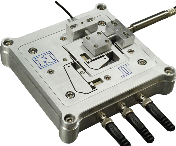
Figure 1. A two-axis serial-kinematic nanopositioning platform with a range of 30 μm.
The position is measured by a Microsense 6810 capacitive sensor and 6504-01 probe, which has a sensitivity of 2.5 μm/V. The stage is driven by two PiezoDrive PDL200 voltage amplifiers with a gain of 20.
The x-axis, which translates from left to right in Figure 1, has a resonance frequency of 513 Hz. The y-axis contains less mass so the resonance frequency is higher at 727 Hz. Since the x-axis imposes a greater limitation on performance, the comparison will be performed on this axis.
The x-axis frequency response for a nominal load is plotted in Figure 2. With the maximum payload, the resonance frequency reduces to 415 Hz. It can be observed that payload mass significantly modifies the higher frequency dynamics.
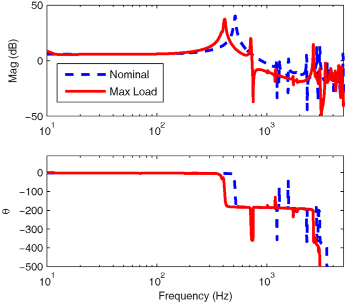
Figure 2. The open-loop frequency response measured from the voltage amplifier input to the sensor output, scaled to μm/V. The frequency response of the x-axis with maximum load is compared to the nominal response.
Since the first resonance mode dominates the response, the dynamics can be approximated by the second-order system
where and are the natural frequency and damping ratio, respectively, and K is the gain of the system. A second-order model is procured using the frequency domain least-squares techniques. The nominal x-axis transfer function is
3. Limitations of PID Control
A popular technique for control of commercial nanopositioning systems is sensor-based feedback using integral or proportional-integral control
Although the derivative term can be used effectively with purely second-order systems, it is rarely used in practice due to the increased noise sensitivity and stability problems associated with high-frequency resonance modes.
The condition for closed-loop stability is approximately (Fleming, 2010)
If the system Gxu(s) is unity gain, the complimentary sensitivity function is
Thus, the feedback gain ki is also the approximate 3-dB bandwidth of the complementary sensitivity function (in radians per second). From this fact and the stability condition [equation (4)], the maximum closed-loop bandwidth is
where the gain-margin is expressed as a linear magnitude rather than in dB. The bandwidth limitations are severe since the damping ratio is usually on the order of 0.01, so the maximum closed-loop bandwidth is <2% of the resonance frequency.
For the nanopositioner under consideration, the maximum permissible gain from equation (6) is 15.5 which is limited by the gain-margin of 6 dB. The closed-loop bandwidth for this controller is only 13 Hz or 2.5% of the resonance frequency. The experimental closed-loop frequency and step responses are plotted in Section 5.
Techniques aimed at improving the closed-loop bandwidth are typically based on either inversion of resonant dynamics using a notch filter or the use of a damping controller. Inversion techniques are popular as they are simple to implement and can provide a high closed-loop bandwidth if they are accurately tuned and the resonance frequency does not vary (Abramovitch et al., 2008). The transfer function of a typical inverse controller is
A major consideration with inversion-based control is the possibility of modeling error. In particular, if the resonance frequency drops below the frequency of the notch filter, the phase lag will cause instability. Therefore, a notch filter must be tuned to the lowest resonance frequency that will occur during service. For example, the example nanopositioner has a nominal resonance frequency of 513 Hz and a minimum resonance frequency 410 Hz. Thus, the notch filter is tuned to 410 Hz with an estimated damping of . To maintain a gain-margin of 6 dB the maximum integral gain is ki = 44.
4. Structured PI Control with IRC Damping
An IRC controller consists of a collocated system Gxu, an artificial feedthrough Df and a controller C. As described in Aphale et al. (2007), the first step in designing an IRC controller is to select, and add, an artificial feedthrough term Df to the original plant Gxu. The new system is referred to as Gxu + Df. It has been shown that a sufficiently large and negative feedthrough term will introduce a pair of zeros below the first resonance mode and also guarantee zero-pole interlacing for higher frequency modes (Aphale et al., 2007). Smaller feedthrough terms permit greater maximum damping. Although it is straightforward to manually select a suitable feedthrough term, it can also be computed from Theorem 2 in Aphale et al. (2007).
For the model Gxu described in equation (2), a feedthrough term of Df = –2.5 is sufficient to introduce a pair of zeros below the first resonance mode. The frequency responses of the open-loop system Gxu and the modified transfer function Gxu + Df are plotted in Figure 3.
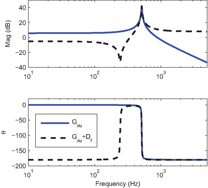
Figure 3. Frequency response of the open-loop system Gxu and with artificial feedthrough Gxu + Df, where Df = −2.5. The 180° phase change of Gxu + Df is due to the negative feedthrough which also makes the system inverting.
Due to the bounded phase of Gxu + Df a simple negative integral controller can be applied directly to the system. That is,
An optimal controller gain k that maximizes damping can be found using the root-locus technique (Aphale et al., 2007). For the system under consideration, the root-locus in Figure 4 produces a gain of k = 1900 and a maximum damping ratio of 0.57.
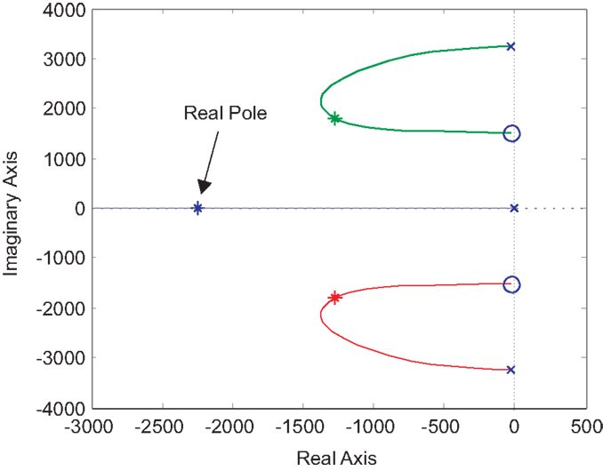
Figure 4. The root-locus of the damped system Gxf. The asterisks mark the optimal pole locations. Note that the closed-loop system contains an additional pole on the real axis.
In order to facilitate a tracking control loop, the feedback diagram must be rearranged in a form where the input does not appear as a disturbance. This can be achieved by finding an equivalent regulator that provides the same loop gain (Fleming et al., 2010). The equivalent regulator C2 is (Fleming et al., 2010):
When the equivalent regulator is
The closed-loop transfer function of the damping loop is
To achieve integral tracking action, the IRC loop can be enclosed in an outer tracking loop as shown in Figure 5. In previous work, an integral controller has been used for tracking control (Fleming et al., 2010). However, from the pole-zero map in Figure 4, it can be observed that the damped system contains the resonance poles, plus an additional real axis pole due to the controller. This additional pole unnecessarily increases the system order and reduces the achievable tracking bandwidth. The location of the additional pole can be found by examining the characteristic equation of the damped system, that is
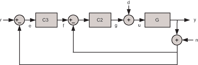
Figure 5. x-axis tracking control system with the damping controller in regulator form C2(s) and the tracking controller C3(s). The signal w is the disturbance input and n is the sensor noise.
If Gxu has the second-order structure described in equation (2), the characteristic equation can be written as
For the system under consideration, the roots of equation (13) contain a complex pair and a pole on the real axis.
To compensate for the additional pole, the controller can be parameterized so that it contains a zero at the same frequency. A controller that achieves this is
where is the frequency of the additional pole. The frequency is the real-valued root of equation (13), which can be found from the root-locus or by using Cardano’s method (Press, 2007), that is
where
With the above parametrization of the tracking controller C3, the loop-gain has integral action from DC until the influence of the first resonance mode. Although this approach is not optimal in any sense, a sensitivity analysis reveals a near-optimal minimization of both the sensitivity function 2 norm and settling-time. Therefore, the proposed approach results in a practically useful controller without the need for non-linear optimization.
For the system under consideration and ki was chosen in the normal way to provide the desired stability margins or bandwidth. The form of C3 is identical to a PI controller except that the zero location is fixed. This is advantageous since the controller has only one free parameter. Note that C3 is inverting to cancel the inverting nature of Gxf. An integral gain of ki = 160 results in a phase margin of 60°. The closed-loop response and performance is examined in Section 5.
The transfer function of the closed-loop system is
or alternatively,
5. Performance Comparison
In Sections 3–4, the controllers were designed to maintain a gain and phase margin of at least 6 dB and 60°. The controller parameters are summarized in Table 1 and the simulated stability margins are listed in Table 2. The integral and inverse controllers were limited by gain-margin, while the damping controller was limited by phase margin.
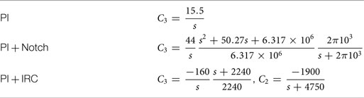
Table 1. Summary of controller parameters.
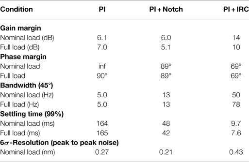
Table 2. Closed-loop performance comparison of the integral, inversion, and damping controllers.
The experimental closed-loop frequency responses are plotted in Figure 6. The frequency where the phase-lag of each control loop exceeds 45° is compared in Table 2.
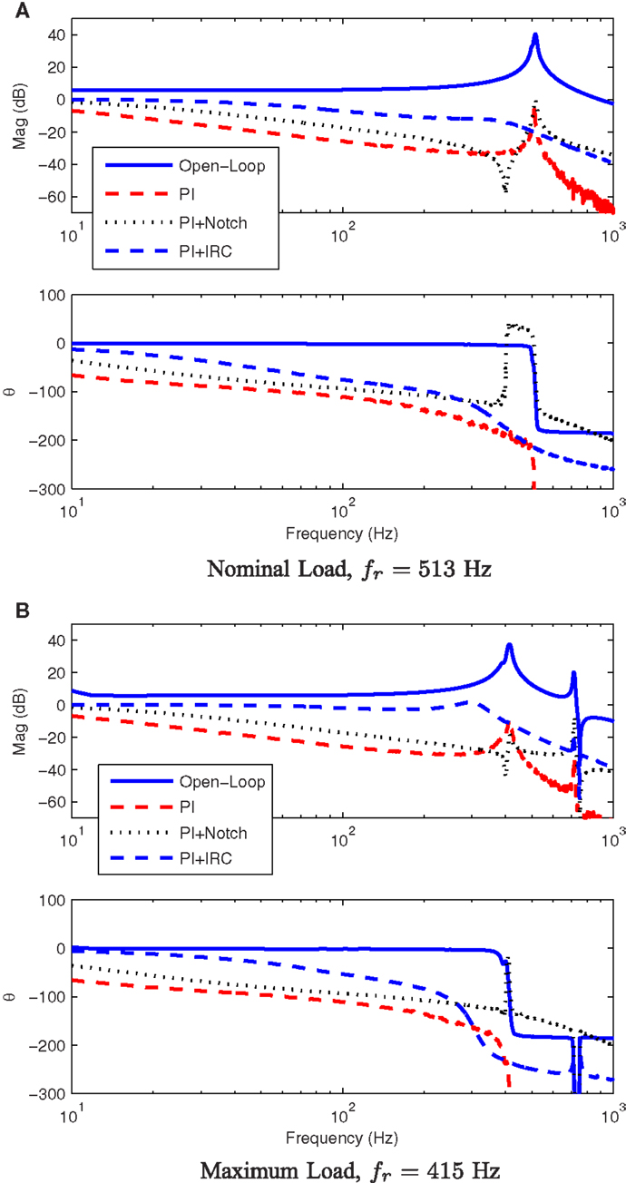
Figure 6. The experimental closed-loop frequency response of each x-axis controller under nominal and maximum load conditions. The nominal response is plotted in (A) while the the perturbed system response is plotted in (B).
The experimental step responses are plotted in Figure 7 and summarized in Table 2. The PI + IRC controller provides the shortest step response by approximately a factor of five; however, the response exhibits some overshoot.
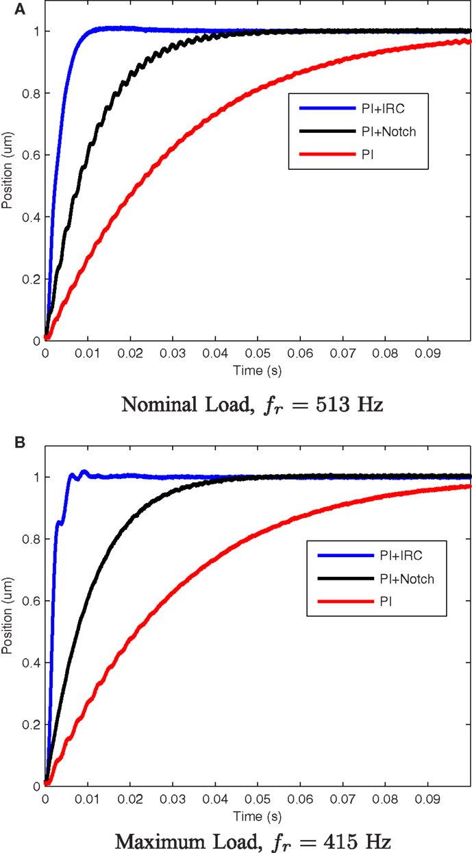
Figure 7. The experimental closed-loop step response of each x-axis controller under nominal and maximum load conditions. The nominal response is plotted in (A) while the the perturbed system response is plotted in (B).
Out of the three controllers, the combination of PI control and IRC provides the best closed-loop performance under both nominal and full-load conditions. This is the key benefit of damping control, it is more robust to changes in resonance frequency than inverse control. If the variation in resonance frequency were less, or if the resonance frequency was stable, there would not be a significant difference between the dynamic performance of an inverse controller and a damping controller. Since the damping controller requires more design effort than an inverse controller, a damping controller is preferable when variance in the resonance frequency is expected, or if there are multiple low-frequency resonances that are difficult to model.
6. Noise and Resolution
The noise sensitivity of each control strategy is the transfer function from the sensor noise n to the actual position y (Fleming, 2013, 2014). For the sake of comparison, the noise contribution of the voltage amplifier is assumed to be small compared to the sensor noise.
For the PI and inverse controller, the noise sensitivity is the complementary sensitivity function with opposite sign; however, with a damping controller as shown in Figure 5, the noise sensitivity is not identical to the complementary sensitivity [equation (16)]. Rather, it is
It can be observed that the noise sensitivity for a standard control loop can be reduced by reducing the closed-loop bandwidth or controller gain. However, with a damping controller, the noise bandwidth is dominated by the damping control loop, not the tracking loop. This is a drawback since the noise bandwidth cannot be reduced by varying the tracking controller gain.
The noise sensitivity of each control strategy is plotted in Figure 8. Due to the wide bandwidth of the damping controller, the noise sensitivity bandwidth is significantly greater than the PI and inverse controllers.

Figure 8. The noise sensitivity of each control strategy.
A straight-forward technique for estimating the positioning resolution is to measure the sensor noise and filter it by the noise sensitivity function. Following the guidelines in Fleming (2013, 2014), the sensor noise was amplified using an SR560 amplifier with a gain of 10,000 and a bandwidth of 0.03–10 kHz. One-hundred seconds of data were recorded at a sampling rate of 30 kHz. A 3-s record of the closed-loop position noise for each controller is plotted in Figure 9. While the PI and inverse controller noise contains low-frequency noise plus randomly excited resonance, the IRC controller resulted in a more uniform spectrum but with a wider noise bandwidth. Considering that the IRC controller increases the closed-loop bandwidth from 5 to 78 Hz (compared to PI control), the decrease in resolution from 0.27 to 0.43 nm is small.
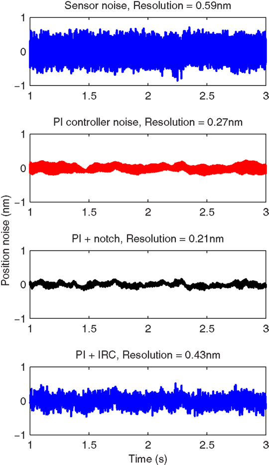
Figure 9. The closed-loop noise of each control strategy and the corresponding 6σ-resolution.
7. Analog Implementation
The IRC damping and tracking controller shown in Figure 5 can be implemented directly with the analog circuit shown in Figure 10. The component values for the PI controller are r3 ac3 = 1/ki and r3 bc3 = 1/ωz. For the IRC damping controller, since k is positive and Df is negative, the component values are r2 ac2 = 1/k, and r2 bc2 = 1/kDf.
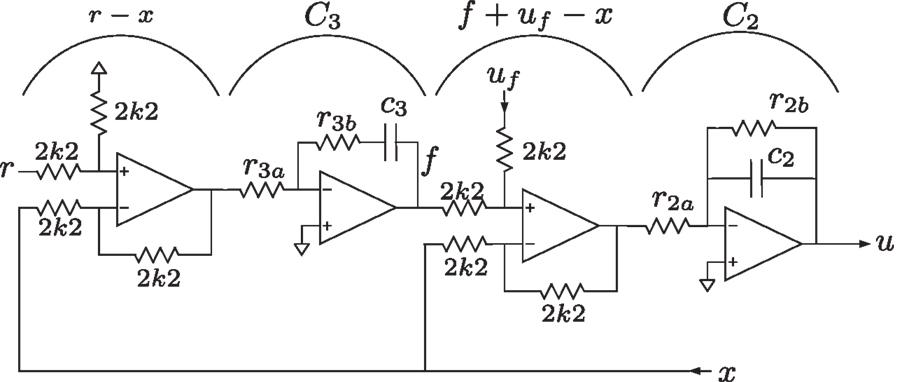
Figure 10. Analog implementation of an IRC damping and PI tracking controller.
8. Application to AFM Imaging
To illustrate the impact of positioning bandwidth on application performance, the nanopositioner was employed for lateral scanning in an atomic force microscope. The AFM head is a NanoSurf EasyScan microscope that is used for holding the cantilever and measuring the deflection. The microcantilever is a Budget Sensors ContAl cantilever with a stiffness of 0.2 N/m and the sample under consideration is a silicon calibration grating with a period of 6 μm and a height of 20 nm.
During scanning, the y-axis is driven by a slow ramp while the x-axis reference is a 10 Hz triangular waveform. Due to the slow scan-rate of the y-axis, the tracking error is negligible. The positioning error of the various x-axis controllers and the resulting image is plotted in Figure 11. The higher bandwidth of the IRC control system is observed to significantly reduce scan-induced imaging artifacts.
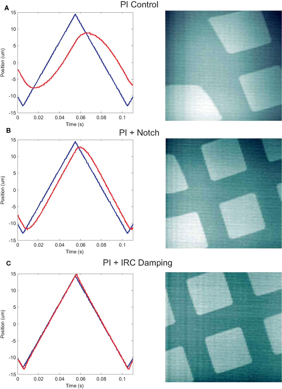
Figure 11. The x-axis scanning performance and resulting image for each of the three controller strategies. The scanning trajectory is a full-range (27 μm) 10 Hz triangle wave. The response and imaging performance of the PI controller is plotted in (A). The improved performance of the inversion and damping controllers can be observed in (B) and (C).
9. Conclusion
This article describes a new method for designing an integral resonance damping controller with integral tracking action. The performance of the new IRC controller is compared to a PI controller and inverse controller that are both common industrial standards.
The integral resonance controller damps the system resonance rather than inverting it. The foremost advantages are simplicity, robustness, and insensitivity to variations in the resonance frequencies. In the experimental comparison, where the resonance frequency varied by 19%, the settling-time of the IRC controller was one-fifth that of the inverse controller.
Conflict of Interest Statement
The authors declare that the research was conducted in the absence of any commercial or financial relationships that could be construed as a potential conflict of interest. The Associate Editor Yuen Kuan Yong declares that, despite being affiliated to the same institution as author Andrew J. Fleming, the review process was handled objectively.
References
Abramovitch, D. Y., Andersson, S. B., Pao, L. Y., and Schitter, G. (2007). “A tutorial on the mechanisms, dynamics, and control of atomic force microscopes,” in Proc. American Control Conference (New York, NY: IEEE), 3488–3502.
Abramovitch, D. Y., Hoen, S., and Workman, R. (2008). “Semi-automatic tuning of PID gains for atomic force microscopes,” in Proc. American Control Conference (Seattle, WA: IEEE), 2684–2689.
Al-Mamun, A., Keikha, E., Bhatia, C. S., and Lee, T. H. (2013). Integral resonant control for suppression of resonance in piezoelectric micro-actuator used in precision servomechanism. Mechatronics 23, 1–9. doi: 10.1016/j.mechatronics.2012.10.001
Aphale, S. S., Bhikkaji, B., and Moheimani, S. O. R. (2008). Minimizing scanning errors in piezoelectric stack-actuated nanopositioning platforms. IEEE Trans. Nanotechnol. 7, 79–90. doi:10.1109/TNANO.2007.910333
Aphale, S. S., Fleming, A. J., and Moheimani, S. O. R. (2007). Integral resonant control of collocated smart structures. IOP Smart Mater. Struct. 16, 439–446. doi:10.1088/0964-1726/16/2/023
Bhikkaji, B., and Moheimani, S. O. R. (2008). Integral resonant control of a piezoelectric tube actuator for fast nanoscale positioning. IEEE ASME Trans. Mechatron. 13, 530–537. doi:10.1109/TMECH.2008.2001186
Butterworth, J. A., Pao, L. Y., and Abramovitch, D. Y. (2012). Analysis and comparison of three discrete-time feedforward model-inverse control techniques for nonminimum-phase systems. Mechatronics 22, 577–587. doi:10.1016/j.mechatronics.2011.12.006
Clayton, G. M., Tien, S., Leang, K. K., Zou, Q., and Devasia, S. (2009). A review of feedforward control approaches in nanopositioning for high-speed SPM. J. Dyn. Syst. Meas. Control 131, 061101. doi:10.1115/1.4000158
Daz, I. M., Pereira, E., and Reynolds, P. (2012). Integral resonant control scheme for cancelling human-induced vibrations in light-weight pedestrian structures. Struct. Control Health Monit. 19, 15–69. doi:10.1002/stc.423
Devasia, S., Eleftheriou, E., and Moheimani, S. O. R. (2007). A survey of control issues in nanopositioning. IEEE Trans. Control. Syst. Technol. 15, 802–823. doi:10.1109/TCST.2007.903345
Eielsen, A. A., Burger, M., Gravdahl, J. T., and Pettersen, K. Y. (2011). “PI2-controller applied to a piezoelectric nanopositioner using conditional integrators and optimal tuning,” in Proc. IFAC World Congress, Vol. 18 (Milano: IFAC), 887–892.
Fanson, J. L., and Caughey, T. K. (1990). Positive position feedback control for large space structures. AIAA J. 28, 717–724. doi:10.2514/3.10451
Fleming, A. J. (2010). Nanopositioning system with force feedback for high-performance tracking and vibration control. IEEE Trans. Mechatron. 15, 433–447. doi:10.1109/TMECH.2009.2028422
Fleming, A. J. (2013). A review of nanometer resolution position sensors: operation and performance. Sens. Actuators A Phys. 190, 106–126. doi:10.1016/j.sna.2012.10.016
Fleming, A. J. (2014). Measuring and predicting resolution in nanopositioning systems. Mechatronics 24, 605–618. doi:10.1016/j.mechatronics.2013.10.003
Fleming, A. J., Aphale, S. S., and Moheimani, S. O. R. (2010). A new method for robust damping and tracking control of scanning probe microscope positioning stages. IEEE Trans. Nanotechnol. 9, 438–448. doi:10.1109/TNANO.2009.2032418
Fleming, A. J., Behrens, S., and Moheimani, S. O. R. (2002). Optimization and implementation of multi-mode piezoelectric shunt damping systems. IEEE ASME Trans. Mechatron. 7, 87–94. doi:10.1109/3516.990891
Fleming, A. J., and Leang, K. K. (2010). Integrated strain and force feedback for high performance control of piezoelectric actuators. Sens. Actuators A Phys. 161, 256–265. doi:10.1016/j.sna.2010.04.008
Fleming, A. J., and Leang, K. K. (2014). Design, Modeling and Control of Nanopositioning Systems. London: Springer.
Fleming, A. J., and Moheimani, S. O. R. (2006). Sensorless vibration suppression and scan compensation for piezoelectric tube nanopositioners. IEEE Trans. Control Syst. Technol. 14, 33–44. doi:10.1109/TCST.2005.860511
Fleming, A. J., and Wills, A. G. (2009). Optimal periodic trajectories for band-limited systems. IEEE Trans. Control Syst. Technol. 13, 552–562. doi:10.1109/TCST.2008.2001375
Kenton, B. J., and Leang, K. K. (2012). Design and control of a three-axis serial-kinematic high-bandwidth nanopositioner. IEEE ASME Trans. Mechatron. 17, 356–369. doi:10.1109/TMECH.2011.2105499
Leang, K. K., Zou, Q., and Devasia, S. (2009). Feedforward control of piezoactuators in atomic force microscope systems. IEEE Control Syst. 29, 70–82. doi:10.1109/MCS.2008.930922
Namavar, M., Fleming, A. J., Aleyaasin, M., Nakkeeran, K., and Aphale, S. S. (2014). An analytical approach to integral resonant control of second-order systems. IEEE ASME Trans. Mechatron. 19, 651–659. doi:10.1109/TMECH.2013.2253115
Petersen, I., and Lanzon, A. (2010). Feedback control of negative-imaginary systems. IEEE Control Syst. 30, 54–72. doi:10.1109/MCS.2010.937676
Press, W. H. (2007). Numerical Recipes 3rd Edition: The Art of Scientific Computing. New York: Cambridge University Press.
Russell, D., Fleming, A. J., and Aphale, S. S. (2015). Simultaneous optimization of damping and tracking controller parameters via selective pole placement for enhanced positioning bandwidth of nanopositioners. J. Dyn. Syst. Meas. Control. 137, 101004. doi:10.1115/1.4030723
Sebastian, A., Pantazi, A., Moheimani, S. O. R., Pozidis, H., and Eleftheriou, E. (2008). “A self servo writing scheme for a MEMS storage device with sub-nanometer precision,” in Proc. IFAC World Congress (Seoul: IFAC), 9241–9247.
Shan, Y., and Leang, K. K. (2012). Accounting for hysteresis in repetitive control design: nanopositioning example. Automatica 48, 1751–1758. doi:10.1016/j.automatica.2012.05.055
Teo, Y. R., and Fleming, A. J. (2015). Optimal integral force feedback for active vibration control. J. Sound Vib. 356, 20–33. doi:10.1016/j.jsv.2015.06.046
Teo, Y. R., Russell, D., Aphale, S. S., and Fleming, A. J. (2014). Optimal integral force feedback and structured pi tracking control: application for high speed confocal microscopy. Mechatronics 24, 701–711. doi:10.1016/j.mechatronics.2014.04.004
Wu, Y., and Zou, Q. (2009). Robust inversion-based 2-DOF control design for output tracking: piezoelectric-actuator example. IEEE Trans. Control Syst. Technol. 17, 1069–1082. doi:10.1109/TCST.2008.2005111
Keywords: scanning probe microscope, integral resonance control, damping control, tracking control, low order
Citation: Fleming AJ, Teo YR and Leang KK (2015) Low-Order Damping and Tracking Control for Scanning Probe Systems. Front. Mech. Eng. 1:14. doi: 10.3389/fmech.2015.00014
Received: 18 August 2015; Accepted: 23 October 2015;
Published: 20 November 2015
Edited by:
Yuen Kuan Yong, The University of Newcastle, AustraliaReviewed by:
Emiliano Pereira, Universidad de Alcalá, SpainMicky Rakotondrabe, Université de Franche-Comté, France
Copyright: © 2015 Fleming, Teo and Leang. This is an open-access article distributed under the terms of the Creative Commons Attribution License (CC BY). The use, distribution or reproduction in other forums is permitted, provided the original author(s) or licensor are credited and that the original publication in this journal is cited, in accordance with accepted academic practice. No use, distribution or reproduction is permitted which does not comply with these terms.
*Correspondence: Andrew J. Fleming, QW5kcmV3LkZsZW1pbmdAbmV3Y2FzdGxlLmVkdS5hdQ==