 Kalen R. Vos
 Gregory M. Shaver
 James McCarthy Jr.
 Lisa Farrell3
- 1Purdue University, West Lafayette, IN, United States
- 2Eaton Valvetrain Engineering, Marshall, MI, United States
- 3Cummins Technical Center, Columbus, OH, United States
Valvetrain flexibility enables the optimization of the engine’s ability to breathe across the operating range, resulting in more efficient operation. The authors have shown the merit of improving volumetric efficiency via valvetrain flexibility to improve fuel efficiency at elevated engine speeds in the previous work. This study focuses on production viable solutions targeting similar volumetric efficiency benefits via delayed intake valve closure at these elevated engine speeds. Specifically, the production viable solutions include reducing the duration at peak lift and reducing the amount of hardware required to achieve a delayed intake closure timing. It is demonstrated through simulation that delayed intake valve modulation at an elevated speed (2,200 RPM) and load (12.7 bar BMEP) is capable of improving volumetric efficiency via a production viable lost motion enabled boot profile shape. Phased and dwell profiles were also evaluated. These profiles were compared against each other for two separately simulated cases: (1) modulating both intake valves per cylinder and (2) modulating one of the two intake valves per cylinder. The boot, phase, and dwell profiles demonstrate volumetric efficiency improvements of up to 3.33, 3.41, and 3.5%, respectively, for two-valve modulation, while realizing 2.79, 2.59, and 3.01%, respectively, for single-valve modulation. As a result, this article demonstrates that nearly all of the volumetric efficiency benefits achieved while modulating IVC via dwell profiles are possible with production viable boot and phased profiles.
1. Introduction
Variable valve actuation (VVA) enables intake and exhaust valve modulation to directly impact the gas exchange process of an engine (Payri et al., 2014). The work described in this article demonstrates production viable methods that include reducing the peak lift duration, as well as requiring less hardware to obtain volumetric efficiency benefits at elevated engine speeds via intake valve closure (IVC) modulation.
Prior research has focused on understanding the impact that IVC modulation has on the engine gas exchange, particularly, advancing or delaying IVC to modulate volumetric efficiency. Vos et al. (2017) demonstrated experimentally that late IVC realizes a 2–5% increase in volumetric efficiency, enabling a 1.2–1.9% improvement in BSFC at elevated engine speeds for a medium-duty diesel engine. Specifically, volumetric efficiency improvements enabled a decrease in BSFC via exhaust gas recirculation (EGR) and start of injection (SOI) optimization without penalizing BSNOx emissions (Vos et al., 2017). Modiyani et al. (2011) showed that both volumetric efficiency and effective compression ratio (ECR) are directly affected by IVC modulation, wherein a one-to-one relationship between volumetric efficiency and ECR occurs. Garg et al. (2016) demonstrated that the pumping mean effective pressure can be reduced via late intake valve closing (LIVC) or early intake valve closing (EIVC). Lancefield and Methley (2000) implemented a model to analyze EIVC and LIVC timings coupled with VGT and EGR settings on a light-duty engine and demonstrated that the amount of inducted charge mass can be altered via IVC timing modulation, resulting in variations in volumetric efficiency. Physically based volumetric efficiency models for diesel engines were investigated in the study by Kocher et al. (2012). The models estimated volumetric efficiency for different IVC timings, engine speeds, and manifold pressures. Benajes et al. (2009) discuss the ability to control in-cylinder thermodynamic conditions, namely ECR and the total intake mass flow, using IVC modulation.
Modulating volumetric efficiency and effective compression ratio (ECR) via LIVC typically involve using a dwell profile, as shown in Figure 1A. Examples of this include, but are not limited to the profiles discussed in the studies by Lancefield (2003); Fessler and Genova (2004); Milovanovic et al. (2004); Yang and Keller (2008); Mahrous et al. (2009); Modiyani et al. (2011); Kocher et al. (2012); Garg et al. (2016); Vos et al. (2017). The drawback of a dwell profile is the large cam profile, as shown in Figure 1A, required to enable the desired LIVC profile via lost motion. Schwoerer et al. (2010) present examples of lost motion enabled production viable strategies for LIVC, internal exhaust gas recirculation (iEGR), early exhaust valve opening (EEVO), and engine breaking. In addition, Schwoerer et al. demonstrate the capability of replicating such profiles on a cam engine via mechanical, electrical, and hydraulic components. Zurface et al. (2012) also discuss production-based strategies in the presence of lost motion. Specifically, a durable solution that enables switching between a nominal intake profile and a smaller intake profile to achieve EIVC with a shortened lift and intake event duration (Zurface et al., 2012).
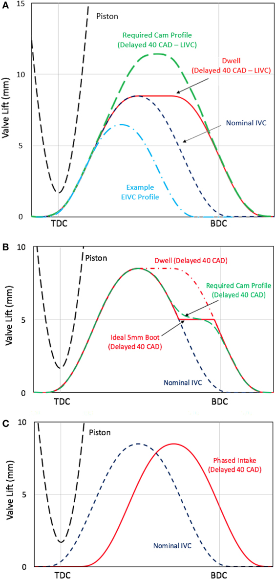
Figure 1. (A) Example of a dwell profile and a required cam profile for an IVC of 40 CAD after nominal. The dark blue dashed line represents the nominal profile, the red solid line represents the dwell profile, the light blue dot-dash line represents an EIVC profile, and the green dashed line represents a cam profile that is required to achieve the LIVC timing via the dwell shape profile. (B) Example of the boot profile with an IVC of 40 CAD after nominal and a height of 5 mm. The blue dashed line represents the nominal profile, the red dashed line represents the dwell profile, the solid red line represents the ideal boot profile, and the green dashed line illustrates a required cam profile to achieve LIVC via the boot. (C) Example of the intake phasing profile used with an IVC timing of 40 CAD after nominal. Both the IVO and IVC were delayed by 40 CAD in this case. The blue dashed line represents the nominal profile, and the solid red line represents the phased profile.
The boot profile differs from the dwell profile by shifting the dwell duration from the peak lift to a lower lift in order to delay IVC, as shown in Figure 1B. These attributes, (1) dwelling at a lower lift and (2) reducing the valve duration at the peak lift, are what characterize the production viability of the added boot shape by providing a more dependable means of achieving LIVC. The benefit is a less aggressive cam profile requirement for implementation via lost motion. Lost motion is defined in this article as a predetermined amount of additional valve lift that forms the LIVC boot profile when aggregated with the nominal valve profile, as shown in Figure 1B. Normally, this additional valve lift is absorbed such that the motion is hidden from the valve event to enable nominal operation. Examples of lost motion enabled hardware include but are not limited to the valvetrain assemblies described in the studies by Schwoerer et al. (2010); Zurface et al. (2012); Radulescu et al. (2013).
Another method is to use added motion to implement LIVC for extending the valve closing event. This implementation would create the normal valve profile as the default configuration. LIVC could be activated by using an additional lift to create the boot shape. The event could be implemented using a switching roller finger follower (SRFF) or alternatively an additional cam profile utilizing a lost motion capsule.
Incorporating a boot for LIVC enables the more production viable cam profile shown in Figure 1B, as opposed to requiring the enlarged cam profile shown in Figure 1A. Implementing the boot profile to achieve LIVC in place of an enlarged cam profile would improve the durability, the packaging size, and the cost effectiveness of the valvetrain. In comparison, dwelling at a lower lift results in smaller forces acting on the valves, allowing a compact and durable solution to be realized at a relatively inexpensive cost. In addition, implementing a lost motion enabled boot profile minimizes the impact of potential critical shifts. Radulescu et al. (2013) defines a critical shift for an EIVC SRFF to be the undesired event that results in a valve being partially lifted and dropped back to the valve seat due to improper latching (Radulescu et al., 2013). This critical shift leads to unintended impact on the system from a momentary loss of control of both the rocker arm and the valve movement. As a result, the potential impact from a critical shift is minimized for the boot profile, in comparison to the enlarged cam profile, which corresponds to a more robust solution for LIVC.
Intake phasing maintains the same duration as the nominal profile while incorporating a desired phase, as illustrated in Figure 1C. Both IVO and IVC are delayed by the same amount to preserve the nominal valve duration and create the phase shift. This can be implemented via production viable cam phaser technology.
In the following, relative volumetric efficiency merits of the dwell, boot, and phased intake strategies are compared and shown to be similar. As a result, production viable boot and phased profiles can be implemented instead of the often studied dwell profile.
1.1. Motivation for Elevated Speed and Load Condition
Figure 2A illustrates the speed-load trajectory, as operated over the Heavy Duty Federal Test Procedure (HDFTP), for the engine used in this effort. The HDFTP is a proxy for diesel engine use in real-world medium and heavy-duty vehicle applications. The amounts of fuel consumed in different operating zones during the HDFTP are reflected in Figure 2B. Approximately 50% of the fuel energy is consumed at elevated speeds near 2,200 RPM and elevated loads of 12.7 bar BMEP and higher. In the previous work, the authors have demonstrated an experimental fuel savings of 1.2% at 2,200 RPM and 12.7 bar BMEP enabled via volumetric efficiency improving LIVC dwell profiles (Vos et al., 2017). However, the efforts described in this article focus on demonstrating similar fuel efficiency enabling volumetric efficiency benefits while utilizing production viable alternatives to these dwell profiles.
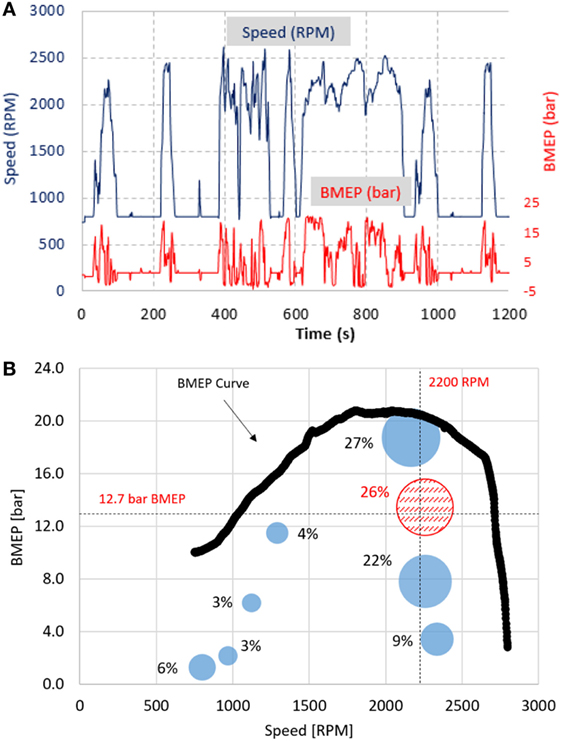
Figure 2. (A) The speed (RPM)–load (BMEP) space corresponding to the engine used in this effort during the HDFTP drive cycle. (B) The HDFTP is mapped to 8 operating conditions, where each bubble corresponds to the percentage of fuel energy spent at/near those operating conditions during the drive cycle.
2. Setup
2.1. Simulation
Gamma Technologies’ engine simulation software (GT-Power) was utilized to model a six-cylinder Cummins diesel engine incorporating valve motion flexibility. The engine includes a cooled high-pressure EGR loop, a variable geometry turbine (VGT), and a high-pressure common rail fuel injection arrangement, as shown in Figure 3A.
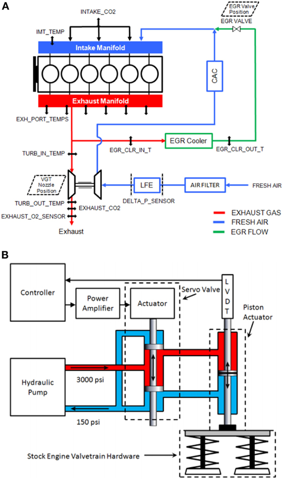
Figure 3. High-level schematic of the experimental test bed setup. (A) Schematic drawing of the air handling system of the engine with the location of sensors having been labeled. (B) Schematic of the variable valve actuation setup.
2.2. Experimental
An experimental test bed was used to validate the simulation model. The test bed includes a medium-duty diesel engine equipped with a fully flexible variable valve actuation (VVA) system that enables cylinder independent, cycle-to-cycle control of the valves.
Figure 3B depicts a hydraulic pump that powers the VVA using oil supplied at 3,000 psi 20.7 MPa. There are two linear electrohydraulic actuators that are located on each 4-valve cylinder head, capable of modulating one pair of intake and one pair of exhaust valves. Individual valve pairs have a linear variable differential transformer (LVDT) that provides position feedback to a real-time controller in dSPACE to govern the linear actuators.
A laminar flow element (LFE) is used to determine the fresh air flow rate through a conditioned combustion air system, which maintains the temperature and relative humidity. The exhaust gas flows through a passively operating aftertreatment system (i.e., no dosing).
The engine’s six cylinders use Kistler 6067 C and AVL QC34C pressure transducers to record in-cylinder pressure by means of an AVL 621 Indicom module. Necessary data are logged and monitored using a dSPACE data acquisition system that interfaces with the experimental test bed. The engine control module (ECM) is directly connected to the dSPACE system for control of air handling actuators such as the EGR valve, the VGT nozzle, and cycle-by-cycle monitoring and control of parameters such as injection timing, fuel quantity, and rail pressure.
3. Simulating Intake Valve Modulation
3.1. Methodology
Simulations were conducted at an elevated speed of 2,200 RPM and a load of 12.7 bar BMEP using GT-Power. The intake valves on each cylinder were modulated to simulate three independent profiles: a dwell profile, a boot profile, and a phased profile, as shown in Figures 1A–C. These three profiles incorporated an IVC sweep ranging between nominal closure timing (0 CAD delayed) and 40 CAD delayed to vary the volumetric efficiency. This study also compares the benefits of modulating both intake valves on each cylinder to only modulating one of the intake valves. “Two-valve modulation” refers to both intake valves adhering to the same desired valve profile strategy during testing. “One-valve modulation” refers to one intake valve adhering to the desired valve profile strategy, while the other intake valve operates nominally. The production viability of modulating only one valve is primarily motivated by its cost effectiveness and packaging size, as less hardware is required to modulate half the valves during operation.
3.1.1. Model/Engine Comparison
The experimental engine test bed setup used in this study is only capable of modulating both intake valves on each cylinder simultaneously. Figures 4A,B show a comparison of experimental and simulation model results for dwell profiles with IVC varying from nominal to 40 CAD delayed. The results are consistent, providing confidence in the models capabilities. Both experimental and simulation model results show an optimal increase in volumetric efficiency for an IVC of ~20 CAD delayed as a result of dynamic charging, as shown in Figure 4A. Dynamic charging is referred to in this study as the process of increasing the charge mass in the cylinder via momentum-enabled improved cylinder filling at elevated engine speeds.
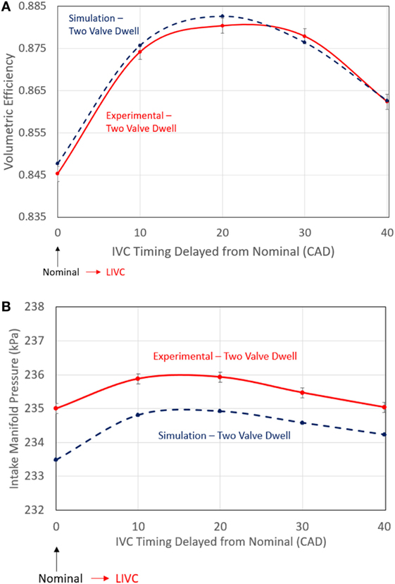
Figure 4. Experimental and simulation results illustrate similar trends over an IVC timing range from nominal to 40 CAD delayed. (A) Intake valve modulation shows a parabolic-like trend for volumetric efficiency for both experimental and simulation results as IVC timing is delayed from 0–40 CAD from nominal. (B) Intake manifold pressure shows similar trends for experimental and simulation results as IVC timing is delayed 0–40 CAD from nominal.
The relationship between volumetric efficiency and charge mass flow rate can be expressed via the “speed-density equation”:
where ω is the engine speed, Vd is the engine displacement, ρchg is the charge density, ηvol is the volumetric efficiency, and is the charge mass flow rate. As shown, volumetric efficiency is directly related to charge flow, whereby a higher volumetric efficiency enables a higher charge flow.
3.2. Results at 2200 RPM 12.7 BMEP
This section demonstrates that nearly all the volumetric efficiency benefits achieved while modulating IVC via dwell profiles, as illustrated in Figures 4A and 5A, are possible with the production viable boot and phased profiles. Figure 5A shows the dwell profiles simulated with IVC timings ranging from nominal (0 CAD delayed) to 40 CAD delayed for both two-valve and one-valve modulation.
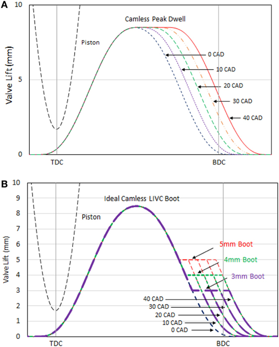
Figure 5. (A) Simulated dwell profiles with IVC timings ranging from nominal (0 CAD) to 40 CAD after nominal. (B) Simulated intake boot profiles with IVC timings ranging from nominal (0 CAD) to 40 CAD after nominal. The boot heights ranged from 3 to 5 mm.
3.2.1. Impact on Volumetric Efficiency
The boot profile can be varied in two locations: (1) the height of the boot and (2) the IVC timing of the profile. Figure 5B shows both of these being varied over a boot height range of 3–5 mm and at IVC timings ranging from nominal to 40 CAD delayed. This effectively enables variability of the valve duration at a lift lower than the peak lift. The boot profile is simulated with both two-valve and one-valve modulation.
Two-valve modulation via GT-Power simulation predicts that a majority of the volumetric efficiency benefits can be achieved using a boot height of 5 mm, as shown in Figure 6A. Boot heights of 4 and 3 mm also perform well.
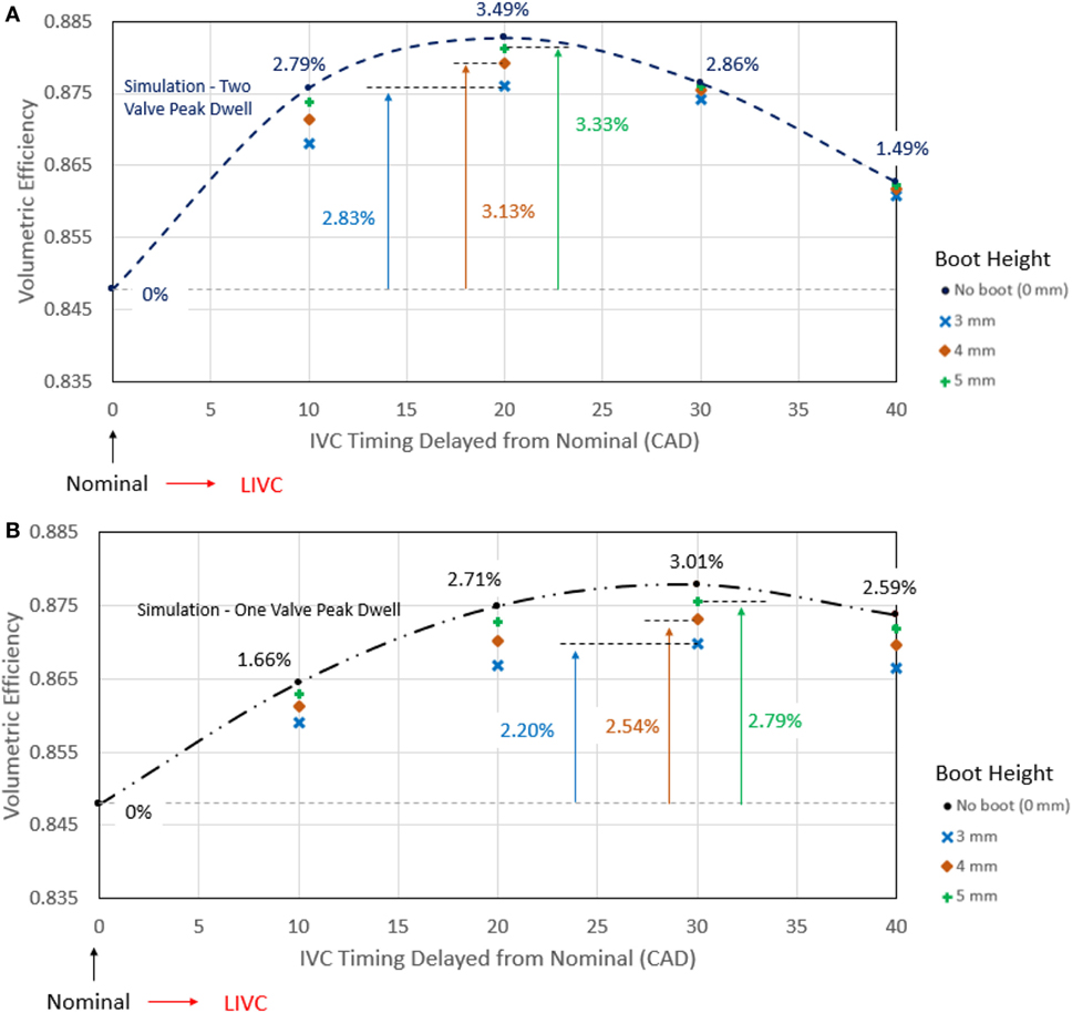
Figure 6. Simulation results for a boot profile where the height of the boot is varied from 3 to 5 mm, and the IVC timing is varied from nominal to 40 CAD delayed. The results for different boot heights were compared to dwelling at the peak of one intake valve, represented by the parabolic-like lines. (A) For a boot profile on both intake valves, the light blue x reflects a boot height of 3 mm, the brown diamond corresponds to 4 mm and the green + corresponds to 5 mm. (B) For a boot profile on one of the two intake valves, the light blue x reflects a boot height of 3 mm, the brown diamond corresponds to 4 mm, and the green + corresponds to 5 mm.
Similarly, one-valve modulation via GT-Power simulation predicts that a majority of the volumetric efficiency benefits can be realized using a boot height of 5 mm, as shown in Figure 6B. However, a slightly more delayed IVC timing of 30 CAD yielded an optimal ~2.79% volumetric efficiency benefit for the 5-mm boot profile. In addition, boot heights of 4 and 3 mm also perform well. Implementing one-valve modulation is a more cost-effective method for obtaining similar volumetric efficiency benefits compared to two-valve modulation.
Figure 7 shows the considered phase profiles over the range of simulated IVC timings. The volumetric efficiency benefits when phasing the intake profile from nominal, for both two-valve and one-valve modulation, are illustrated in Figures 8A,B respectively.
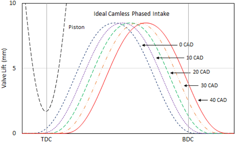
Figure 7. Simulated intake phasing profile with IVO/IVC timings ranging from nominal (0 CAD) to 40 CAD after nominal.
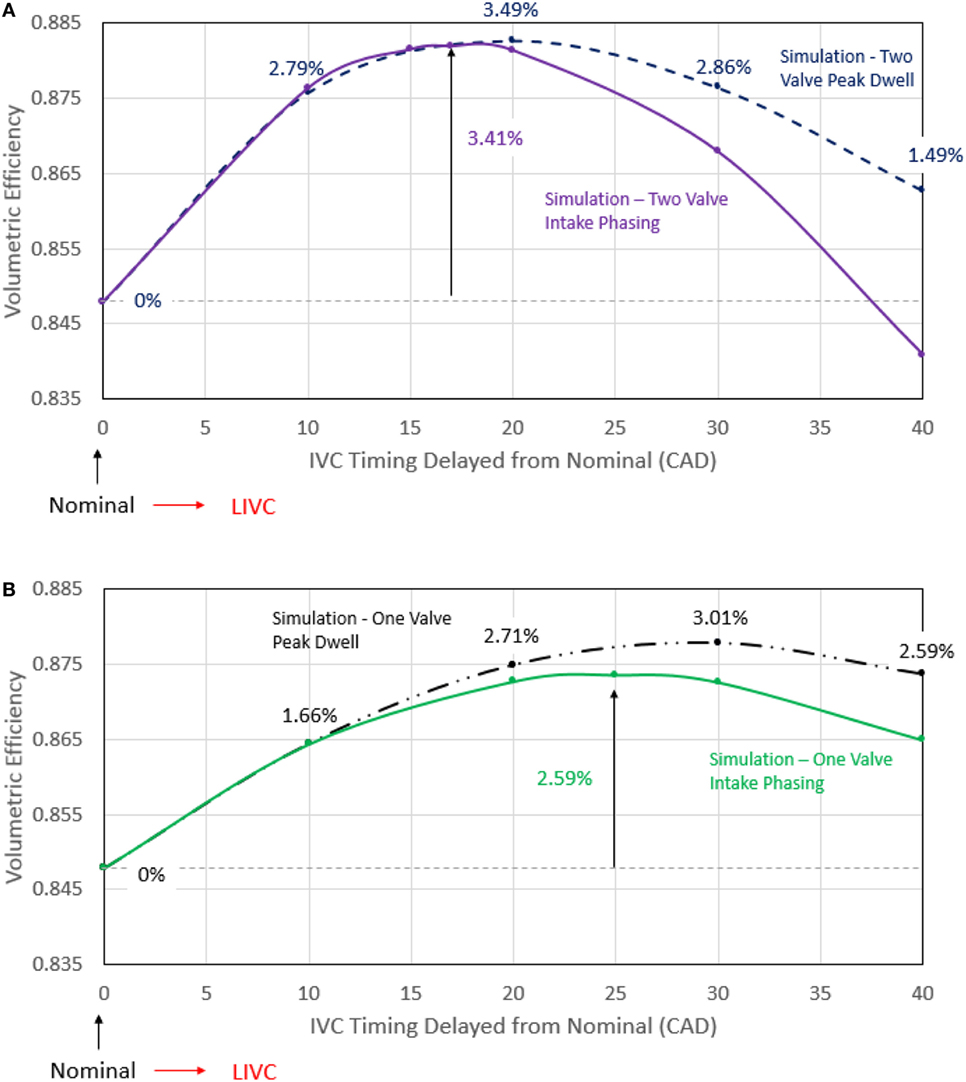
Figure 8. (A) IVC and IVO timing are varied from nominal to 40 CAD delayed on both intake valves. The blue dashed line represents only the IVC delayed from nominal with a dwell at the peak of the intake valve, while the solid purple line corresponds to phasing the intake. (B) IVC and IVO timing are varied from nominal to 40 CAD delayed on one intake valve. The black dashed line represents IVC delayed from nominal with a dwell at the peak of one intake valve, while the solid green line corresponds to phasing one intake valve.
Simulation for the phased intake profile predicts a phase delay of 17 CAD to be optimal with a 3.41% benefit in volumetric efficiency, very similar to that achieved via LIVC with a dwell profile, as shown in Figure 8A. There is 0.08% difference in peak volumetric efficiency benefits between these two trends for two-valve modulation, meaning that phasing the intake valve achieves nearly all of the volumetric efficiency benefit compared to dwelling the intake valve. However, Figure 8A shows that volumetric efficiency is notably more sensitive to phase timing. This is apparent in the sharp decrease of volumetric efficiency after phasing past ~17 CAD.
Figure 8B illustrates a direct comparison between dwelling and phasing for various IVC timings when modulating only one of the intake valves. A majority of the volumetric efficiency benefit, 2.59%, results when phasing the intake from nominal to 25 CAD delayed. There is 0.4% difference in peak volumetric efficiency benefits between these two trends for one-valve modulation, meaning that phasing the intake valve achieves a majority of the volumetric efficiency benefit compared to dwelling the intake valve. Delaying the amount of phase beyond ~25 CAD triggers a more rapid decrease in the volumetric efficiency compared to the dwell profile cases.
3.2.2. Impact on Mass Flow
Figure 9 illustrates the mass flows that correspond to dwell profiles ranging from nominal to 40 CAD delayed. GT-Power simulation captures the effect of dynamic charging at elevated engine speeds via LIVC with dwell profiles, in which an increase in flow momentum enabled more mass to enter the cylinder. This increase in mass flow accounts for the volumetric efficiency improvements discussed earlier. GT-Power also predicts a small amount of backflow (i.e., negative mass flow rate) into the intake manifold during the intake valve opening. IVO timings before the piston reaches TDC, as shown in Figure 9, allow the piston to expel a small amount of trapped mass out of the cylinder and into the intake manifold before inducting mass during the remainder of the intake stroke. Similarly, delaying IVC timings after BDC increases the amount of backflow, which results from the piston motion pushing mass out of the cylinder before the intake valve closes.
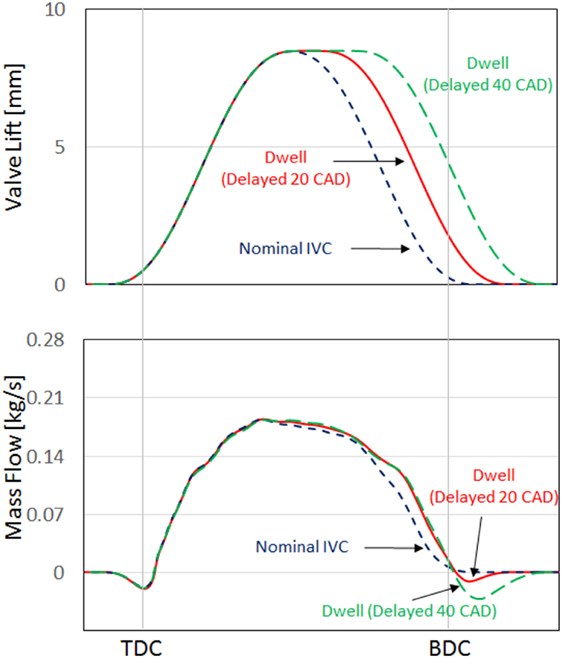
Figure 9. Two-valve modulation for a nominal profile and dwell profiles with IVC timings of 20 CAD and 40 CAD delayed. The top image shows the valve profiles that correspond to the mass flows in the bottom image.
The boot profiles realize a similar increase to mass flow, compared to the dwell profiles, at heights of 3, 4, and 5 mm, as shown in Figure 10. Dynamic charging, characterized by momentum-enabled improved cylinder filling at elevated engine speeds, is most evident at an LIVC timing of 20 CAD after nominal and a boot height of 5 mm. However, boot heights of 3 and 4 mm are possible without degrading most of the benefits from dynamic charging.
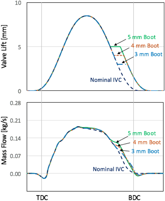
Figure 10. Two-valve modulation for a nominal profile and boot profiles with an IVC timing of 20 CAD delayed and boot heights of 3, 4, and 5 mm. The top image shows the valve profiles that correspond to the mass flows in the bottom image.
The phased profiles realize a delayed increase in mass flow rate, compared to the nominal profile, per Figure 11. This results from a delayed IVO timing, in which the in-cylinder pressure decreases as the piston begins moving from TDC to BDC before the intake valve opens. The difference between the intake manifold pressure (IMP) and the in-cylinder pressure enables a significant inrush of mass upon opening the intake valve and allows the mass flow to increase rapidly. Figure 11 also illustrates dynamic charging for phase timings as late as 40 CAD after nominal. In addition, backflow occurs for IVC timings after BDC, in which the piston pushes mass out of the cylinder before the intake valve closes.
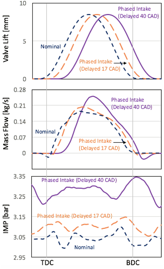
Figure 11. Two-valve modulation for a nominal profile and phased profiles with valve timings of 17 CAD and 40 CAD delayed. The top image shows the valve profiles that correspond to the mass flows in the middle image and the intake manifold pressures in the bottom image.
Table 1 conveys the overall volumetric efficiency benefits for the boot and phase profiles relative to the optimal volumetric efficiency obtained while dwelling both intake valves. The 5-mm boot profile and the phasing profile yield favorable and production viable volumetric efficiency benefits.
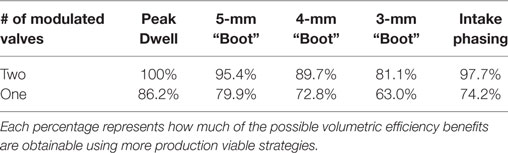
Table 1. Percentages are relative to the dwell profile results for two-valve modulation.
3.2.3. Impact on Effective Compression Ratio
Volumetric efficiency and ECR have been shown in previous studies to be related when modulating LIVC timings via dwell profiles (Modiyani et al., 2011). The following simplified equation was used to compute ECR:
where the effective volumes at IVC and TDC were obtained via the pressure-based method discussed in the study by Modiyani et al. (2011).
Boot profiles realize volumetric efficiency benefits, as shown in Figures 6A,B, and Table 1, while maintaining a similar relationship with ECR, as shown in Figure 12A. The efforts here show that a one-to-one relationship between volumetric efficiency and ECR results for both two-valve modulation as well as one-valve modulation, for both the dwell and the boot profiles. Phasing the intake results in a more complex relationship between volumetric efficiency and ECR, as illustrated in Figure 12B. This relationship results from instances where volumetric efficiency is decreasing, while ECR is increasing. Specifically, Figure 11 shows that for a phasing timing of 40 CAD delayed from nominal, the following occur: (1) ECR increases due to more mass entering the cylinder, and (2) volumetric efficiency decreases due to a significant increase in IMP. Therefore, the relationship between ECR and volumetric efficiency for intake phasing is dependent on the complex nature of the cylinder gas exchange and IMP.
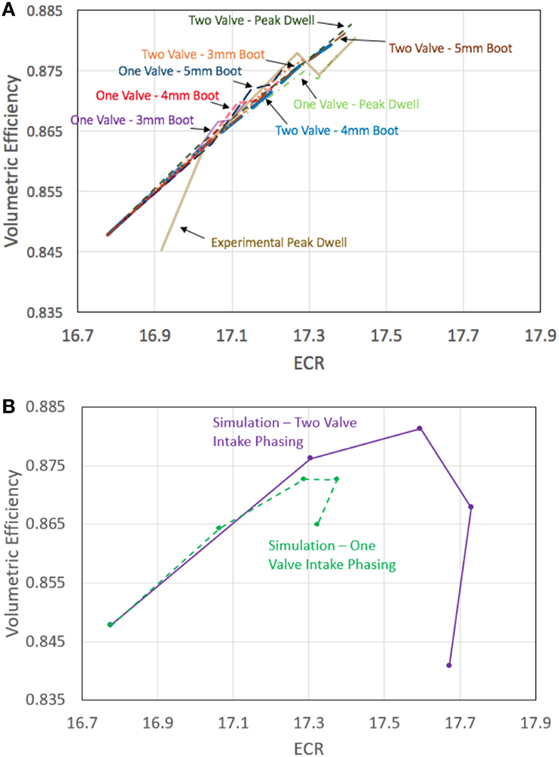
Figure 12. (A) Monotonic relationship between volumetric efficiency and ECR for dwell and boot profiles. (B) Complex relationship between volumetric efficiency and ECR for phasing profiles.
3.2.4. Impact on Open Cycle Efficiency (OCE)
Intake valve phasing results in larger pumping loops, a s shown in Figures 13A,B. This is a result of delaying the IVO timing after TDC, effectively creating an in-cylinder pressure drop that enlarges the pumping loop and decreases the open cycle efficiency (OCE), as shown in Figures 14A,B, which is detrimental to overall engine efficiency. Specifically, OCE is a metric for quantifying the effectiveness of the cylinder gas exchange, and it is directly proportional to the overall engine efficiency. Figures 14A,B also show that dwell and boot profiles exhibit no decrease in OCE, primarily because these valve profiles do not alter the nominal IVO timing. Therefore, implementing a boot profile does not realize the negative impact to OCE that occurs when phasing the intake. In addition, the impact on the gas exchange when modulating only one valve is shown to be similar to modulating two valves.
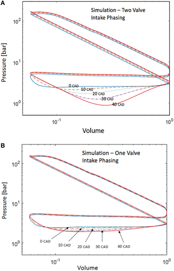
Figure 13. (A) PV diagram for intake phasing two valves. The numbers 0–40 dictate the amount in CAD phased from nominal, 0 denoting nominal operation. (B) PV diagram for intake phasing one valve, while holding the other to nominal IVO/IVC timings. The numbers 0–40 dictate the amount in CAD phased from nominal, 0 denoting nominal operation.
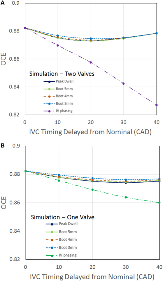
Figure 14. (A) Two-valve modulation of boot and dwell profiles experience similar trends in OCE. Phasing the intake profile realizes degradation in OCE. (B) One-valve modulation of boot and dwell profiles experience similar trends in OCE. Phasing the intake profile realizes degradation in OCE.
In summary, intake valve phasing results in the following detrimental effects:
(1) a sensitive IVC and volumetric efficiency relationship (Figures 8A,B),
(2) a complex volumetric efficiency and ECR relationship (Figure 12B), and
(3) a decrease in OCE (Figures 14A,B).
As a result, the lost motion enabled boot profiles are the preferred production viable means for realizing volumetric efficiency improvements through LIVC timings at elevated engine speeds in cam engine.
4. Summary and Conclusion
IVC modulation is commonly cited as a strategy for altering volumetric efficiency through increased dwell at peak lift of the profile. Previous work by the authors has demonstrated the merit behind improving volumetric efficiency via LIVC dwell profiles as a means to improving fuel efficiency (Vos et al., 2017). The efforts described in this article focus on demonstrating that production viable alternatives to these dwell profiles can achieve a similar impact on volumetric efficiency.
Specifically, a boot profile with a height of 5 mm on both intake valves realizes 95.4% of the volumetric efficiency benefits achieved via the dwell profile at the 2,200 RPM, 12.7 bar BMEP operating condition. In addition, implementing the boot profile reduces the amount of lost motion required, improving the production viability and durability. Modulating only one of the two intake valves as a boot with LIVC realizes 79.9% of the volumetric efficiency benefit. One-valve modulation is more cost effective than two-valve modulation, primarily because half of the hardware is required. Boot heights of 3 and 4 mm yield appreciable volumetric efficiency benefits, for both one-valve and two-valve modulation scenarios.
IVC delay via intake valve phasing realizes 97.7 and 74.2% of the volumetric efficiency benefit achieved through dwell profiles for single- and two-valve modulation, respectively. However, phasing has the following disadvantages: (1) a sensitive IVC and volumetric efficiency relationship, (2) a complex volumetric efficiency and ECR relationship, and (3) a significant decrease in OCE. Lost motion enabled boot profiles are therefore the preferred production viable strategy for realizing volumetric efficiency improvements through LIVC timings at elevated engine speeds in cam engine.
Nomenclature
| BDC | Bottom Dead Center |
| BMEP | Brake Mean Effective Pressure |
| BTE | Brake Thermal Efficiency |
| CAD | Crank Angle Degree(s) |
| ECM | Engine Control Module |
| ECR | Effective Compression Ratio |
| EGR | Exhaust Gas Re-circulation |
| EIVC | Early Intake Valve Closure |
| IMP | Intake Manifold Pressure |
| IVC | Intake Valve Closing |
| LFE | Laminar Flow Element |
| LIVC | Late Intake Valve Closure |
| LVDT | Linear Variable Differential Transformer |
| OCE | Open Cycle Efficiency |
| RPM | Revolutions Per Minute |
| TDC | Top Dead Center |
| VGT | Variable Geometry Turbine |
| VV | Variable Valve Actuation |
Author Contributions
GS: graduate student mentorship and analysis of strategy development. KV: lead writer and researcher that did the analysis and wrote most of the paper. JM: industrial perspective on production-viable valve profiles to consider. LF: essential hardware and software support.
Conflict of Interest Statement
The authors declare that the research was conducted in the absence of any commercial or financial relationships that could be construed as a potential conflict of interest.
Acknowledgments
This project is funded by Cummins Inc. and Eaton, with experiments performed at Ray W. Herrick laboratories in Purdue University. The medium-duty engine was provided by Cummins Inc., along with ample technical assistance provided by both Cummins Inc. and Eaton. The authors would also like to thank their colleagues Mrunal Joshi, Alexander Taylor, Troy Odstrcil, Matthew Van Voorhis and the shop staff at Herrick labs, particularly David Meyer, for the immense support he has extended toward this work.
References
Benajes, J., Molina, S., Martin, J., and Novella, R. (2009). Effect of advancing the closing angle of the intake valves on diffusion-controlled combustion in a HD diesel engine. Appl. Therm. Eng. 29, 1947–1954. doi: 10.1016/j.applthermaleng.2008.09.014
Fessler, H., and Genova, M. (2004). An electro-hydraulic lost motion VVA system for a 3.0 liter diesel engine. SAE Trans. 113, 1639–1649. doi:10.4271/2004-01-3018
Garg, A., Magee, M., Ding, C., Roberts, L., Shaver, G., Koeberlein, E., et al. (2016). Fuel-efficient exhaust thermal management using cylinder throttling via intake valve closing timing modulation. Proc. Inst. Mech. Eng. D J. Automob. Eng. 230, 470–478. doi:10.1177/0954407015586896
Kocher, L., Koeberlein, E., Van Alstine, D., Stricker, K., and Shaver, G. (2012). Physically based volumetric efficiency model for diesel engines utilizing variable intake valve actuation. Int. J. Eng. Res. 13, 169–184. doi:10.1177/1468087411424378
Lancefield, T. (2003). The Influence of Variable Valve Actuation on the Part Load Fuel Economy of a Modern Light-Duty Diesel Engine. SAE 2003-01-0028. Detroit, MI.
Lancefield, T., and Methley, I. (2000). The Application of Variable Event Valve Timing to a Modern Diesel Engine. SAE 2000-01-1229. Detroit, MI.
Mahrous, A.-F. M., Potrzebowski, A., Wyszynski, M., Xu, H., Tsolakis, A., and Luszcz, P. (2009). A modelling study into the effects of variable valve timing on the gas exchange process and performance of a 4-valve DI homogeneous charge compression ignition (HCCI) engine. Energy Convers. Manag. 50, 393–398. doi:10.1016/j.enconman.2008.09.018
Milovanovic, N., Chen, R., and Turner, J. (2004). Influence of Variable Valve Timing on the Gas Exchange Process in a Controlled Auto-Ignition Engine. IMechE D14403. Epinal Way, Loughborough.
Modiyani, R., Kocher, L., Van Alstine, D., Koeberlein, E., Stricker, K., Meckl, P., et al. (2011). Effect of intake valve closure modulation on effective compression ratio and gas exchange in turbocharged multi-cylinder engines utilizing EGR. Int. J. Eng. Res. 12, 617–631. doi:10.1177/1468087411415180
Payri, F., Luján, J., Guardiola, C., and Pla, B. (2014). A challenging future for the IC engine: new technologies and the control role. Oil Gas Sci. Technol. Rev. dIFP Energies Nouv. 70, 15–30. doi:10.2516/ogst/2014002
Radulescu, A., Brownell, S., and McCarthy, J. Jr. (2013). Development of a switching roller finger follower for cylinder deactivation in gasoline engine applications. SAE Int. J. doi:10.4271/2013-01-0589
Schwoerer, J., Kumar, K., Ruggiero, B., and Swanbon, B. (2010). Lost-Motion VVA Systems for Enabling Next Generation Diesel Engine Efficiency and After-Treatment Optimization. SAE Technical Paper, 01(1189). Detroit, MI.
Vos, K. R., Shaver, G. M., Lu, X., Allen, C. M., James McCarthy, J., and Farrell, L. (2017). Improving diesel engine efficiency at high speeds and loads through improved breathing via delayed intake valve closure timing. Int. J. Eng. Res. doi:10.1177/1468087417743157
Yang, B. and Keller, P. (2008). Analysis of Diesel Engine Emissions Reduction by Late Intake Valve Closure and VGT Turbocharger Using 1-D Simulation. SAE 2008-01-2444. Rosemont, IL.
Keywords: variable valve actuation, volumetric efficiency, intake boot, intake phasing, intake dwell, intake valve modulation
Citation: Vos KR, Shaver GM, McCarthy J Jr. and Farrell L (2018) Utilizing Production Viable Valve Strategies at Elevated Speeds and Loads to Improve Volumetric Efficiency via Intake Valve Modulation. Front. Mech. Eng. 4:2. doi: 10.3389/fmech.2018.00002
Received: 09 October 2017; Accepted: 26 January 2018;
Published: 26 February 2018
Edited by:
Evangelos G. Giakoumis, National Technical University of Athens, GreeceReviewed by:
George Kosmadakis, Agricultural University of Athens, GreeceEfthimios G. Pariotis, Hellenic Naval Academy, Greece
Copyright: © 2018 Vos, Shaver, McCarthy and Farrell. This is an open-access article distributed under the terms of the Creative Commons Attribution License (CC BY). The use, distribution or reproduction in other forums is permitted, provided the original author(s) and the copyright owner are credited and that the original publication in this journal is cited, in accordance with accepted academic practice. No use, distribution or reproduction is permitted which does not comply with these terms.
*Correspondence: Gregory M. Shaver, Z3NoYXZlckBwdXJkdWUuZWR1