 Jing-Shan Zhao
 Song-Tao Wei
- State Key Laboratory of Tribology, Department of Mechanical Engineering, Tsinghua University, Beijing, China
This paper proposes a kinematics algorithm in screw coordinates for articulated linkages. As the screw consists of velocity and position variables of a joint, the solutions of the forward and inverse velocities are the functions of position coordinates and their time derivatives. The most prominent merit of this kinematic algorithm is that we only need the first order numerical differential interpolation for computing the acceleration. To calculate the displacement, we also only need the first order numerical integral of the velocity. This benefit stems from the screw the coordinates of which are velocity components. Both the forward and the inverse kinematics have the similar calculation process in this method. Through examples of planar open-chain linkage, single closed-chain linkage and multiple closed-chain linkage, the kinematics algorithm is validated. It is particularly fit for developing numerical programmers for forward and inverse kinematics in the same procedures, including the velocity, displacement and acceleration which provide the fundamental information for dynamics of the linkage.
Introduction
Kinematics of a linkage aims at studying its motion without regard to forces (Norton, 2004) for the synthesis of a mechanism (Suh and Radcliffe, 1978) or to accomplish the desired motion (Shigley and Uicher, 1980) and determine its rigid-body dynamic behavior (Bottema and Roth, 1979; Waldron and Kinematics, 2004). Kinematic geometry (Hunt, 1978), geometric design (McCarthy and Soh, 2011), theoretical kinematics of robotic mechanisms (McCarthy, 1990; Duffy, 1996; Davidson and Hunt, 2004; Dai, 2014), and the analysis, synthesis and optimization of spatial kinematic chains (Angeles, 1982) are elaborated in previous works in the past decades. Kinematic analysis of a linkage requires the algebraic equations that might be iterated numerically. Computational kinematic analysis plays a vital role in the study of a mechanical system (Saura et al., 2019). It is the most straightforward procedure for kinematics and dynamics to select the absolute coordinates of the reference point as the variables (García de Jalón and Bayo, 1994). This selection has the advantage of normally leading to a facilitated expression for the constraints and Jacobian matrices of a multi-body system (García de Jalón and Bayo, 1994). The forward kinematics of a serial linkage is easier than its inverse kinematics while the forward kinematics of a parallel linkage is more complex than its inverse kinematics (Suh and Radcliffe, 1978; Bottema and Roth, 1979; Duffy, 1980; Shigley and Uicher, 1980; Angeles, 1982; García de Jalón and Bayo, 1994; Duffy, 1996).
In the past half century, parallel manipulators witnessed very quick development. Parallel manipulators have been attracted a great attention ever since the industry application of Gough’s tire testing machine and Stewart’s platform for its superior performance over its serial counterparts in terms of loading capacity, rigidity and accuracy (Gough and Whitehall, 1962; Stewart, 1965). However, the forward kinematics usually contains a group of nonlinear algebraic equations that are complexly coupled and there are no general methods to solve them analytically (Chapelle and Bidaud, 2004; Wu et al., 2009). It has been recognized as the general purpose of a software that standardized procedures should be proposed for reducing the kinematic analysis of mechanism to simplify the problem (Kong et al., 2016). Different procedures were developed to establish the restriction equations to solve their time derivatives of first and second orders (Zhao et al., 2016). Actually, such procedures can be accomplished through vector-loop processing for planar linkages (Brát and Lederer, 1973; Kong et al., 2018). The forward kinematics are either established in the functions of structure parameters and input variables numerically (Yang et al., 2018) or presented in algebraic coordinates (Wu et al., 2013; Kong et al., 2019). The inverse kinematic problem consists of finding the joint variables to achieve a desired configuration of a mechanism (Chapelle and Bidaud, 2004; Wu et al., 2013).
To understand the kinematic performance of a linkage, many scholars have been proposing different theories (McCarthy, 1990; Duffy, 1996; Davidson and Hunt, 2004; Dai, 2014; Zhao et al., 2016; Amiri and Mazaheri, 2020; Faghidian and Mohammad-Sedighi, 2020), methods (Angeles, 1982; Kong et al., 2018; Yang et al., 2018; Kong et al., 2019; Shen et al., 2020), algorithms (García de Jalón and Bayo, 1994; Kong et al., 2016; Saura et al., 2019) and software (Brát and Lederer, 1973; García de Jalón and Bayo, 1994; Wu et al., 2009; Wu et al., 2017). This paper focuses on an algorithm in the screw coordinates to solve the velocity of articulated planar linkage and investigates the displacement and acceleration. A screw is a line vector accompanied by a secondary vector attached with a pitch. As the geometrical element, a screw with six components plays a vital role in kinematics and mechanics of a mechanism (Barus, 1900). The paper develops an algorithm to analyze the displacement, velocity and acceleration of articulated planar mechanisms in twist coordinates of each joint. This is the first try to use screw coordinates to completely study the displacement, velocity and acceleration of linkages in a general systematic way. Because the kinematics analysis starts from the velocity, the solutions of forward and inverse kinematics of a mechanism have the same form in expression which facilitates the programming and calculation. The discussion is not restricted to the kinematics of revolute jointed planar linkages, and the similar principles also apply to spatial mechanisms.
Instantaneous Twist of the End Effector of a Series Mechanism
Definition of Twist
Table 1 is the definition of parameters in this paper.
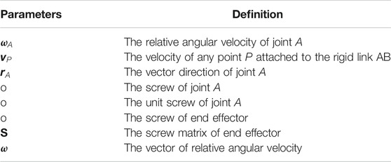
TABLE 1. Definition of parameters.
Figure 1A shows an articulated link
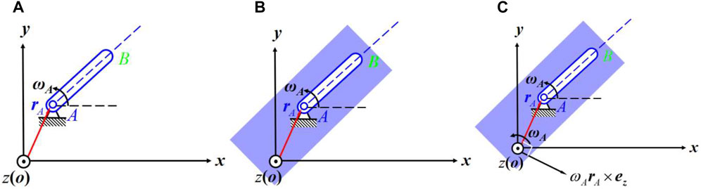
FIGURE 1. Twist of a revolute jointed link.
Also, there is
where
where
where
In Equation 3, the first three components indicate the unit direction of a rotation and the last three components present implicitly the position of the axis of rotation with respect to the origin of the coordinate system (Zhao et al., 2014). Therefore, Equation 2 can be denoted by
Twist Matrix of a Series Pivoted Kinematic Chain
When a second link

FIGURE 2. Twist of link
With the similar procedure mentioned above, we get
where
According to the principle of linear superposition, the absolute angular velocity of link
and the absolute velocity of link
where
As a result, the twist of link
Equation (9) can be rewritten as
which can be expressed in matrix multiplication form:
where
Similarly, the twist of the end effector, denoted by
where
and
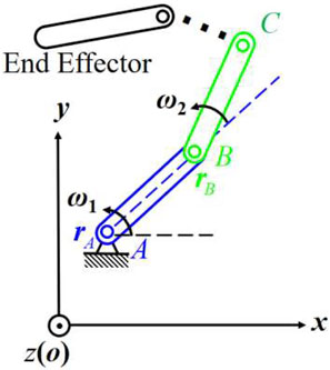
FIGURE 3. A series kinematic chain.
Eq. 13 is called the unit twist matrix of a serial linkage while Equation 14 presents a vector including all relative angular speeds of each joint relative to its previous neighbor in the kinematic chain. Screw matrix 13) is made up of the geometry parameters of the mechanism. It can be programmed in the computer software. This procedure offers an explicit inference of kinematic attributes for velocities in the mechanisms that have the same topology.
Kinematics of a Revolute Jointed Mechanism With Serial Open Chain
From Equation 12, we know that the twist of the end effector with a marking point of the origin of the coordinate frame can be directly obtained when
We know that
where
where
After knowing the twist of the end effector with a marking point of the origin
where
When
where
Figure 4 shows a planar linkage in series. In the absolute coordinate system, we gain the twist of the end effector:
where
and
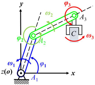
FIGURE 4. A planar open chain linkage of 3 degrees of freedom.
Supposing the length of the links are
In accordance to Equation 17, we know that the twist of the end effector with the marking point on its center is
where
By programming with the numerical algorithms, we obtain the forward kinematics of the linkage. With the initial conditions of
Then we get the successive parameters of
where
The angular accelerations of each joint can be numerically calculated by
where
In forward kinematic, we let the angular velocity of screw joint

TABLE 2. Structure parameters and initial conditions.
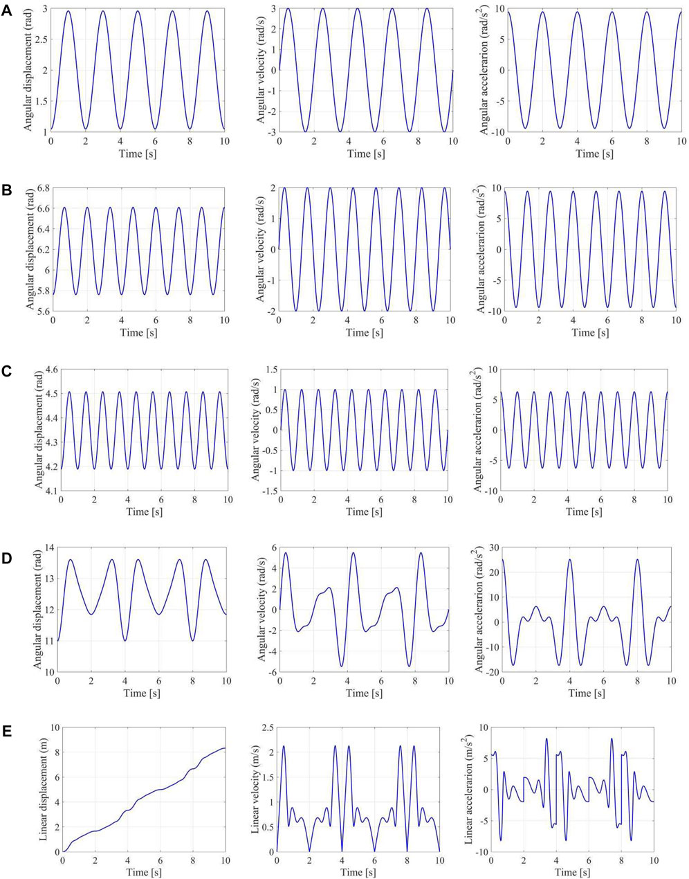
FIGURE 5. Forward kinematics of a planar 4-bar mechanism. (A) Angular displacement, velocity and acceleration of joint A1; (B) Angular displacement, velocity and acceleration of joint A2; (C) Angular displacement, velocity and acceleration of joint A3; (D) Angular displacement, velocity and acceleration of end effector; (E) Linear velocity and acceleration of the center of end effector.
Kinematics of Pivoted Linkages of Closed Chain
Kinematics of the 4-bar Linkage
Figure 6 1) shows a planar 4-bar linkage in series and 2) a 4-bar mechanism with closed loop. The twist of the end effector of the 4-bar linkage in series can be gained from Equation 12:
where
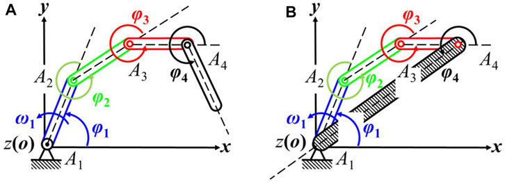
FIGURE 6. Planar 4-bar linkages. (A) A 4-bar linkage in series; (B) A 4-bar linkage with closed loop.
Eq. 12 indicates that the kinematic chain forms a closed loop when the end effector is fixed with the frame (see Figure 6B). And therefore, there must be
Eq. 28 is called the loop equation of the mechanism which can be used to solve all angular velocities by taking other known conditions into account. In the coordinate frame shown in Figure 6,
where
Rearranging equation (29) presents
Therefore, we gain the forward kinematics of the closed-chain 4-bar linkage (Figure 6B):
where
When the output of
Consequently, the inverse kinematics of the 4 bar mechanism is now rewritten as
where
In this regard, the forward velocity and inverse velocity have the same form in mathematical expressions which is one of the advantages of this algorithm. Then, we get the successive parameters of
where
Compared with the Denavit-Hartenberg notation for a closed loop (Craig, 1986), the kinematics algorithm in screw form here only requires to implement one numerical integration 32) for displacement and one numerical differential 27) for acceleration in the absolute coordinate frame. This provides a more convergent algorithm to develop computational kinematics of a linkage. We let the angular velocity of joint

TABLE 3. Structure parameters and initial conditions.
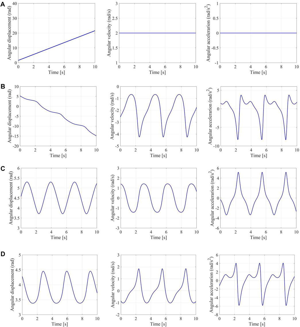
FIGURE 7. Forward kinematics of a planar 4-bar linkage. (A) Angular displacement, velocity and acceleration of joint A1; (B) Angular displacement, velocity and acceleration of joint A2; (C) Angular displacement, velocity and acceleration of joint A3; (D) Angular displacement, velocity and acceleration of joint A4.
Kinematics of an Articulated Linkage of 1 degree of Freedom With Multiple Closed Chains
Figure 8 illustrates a planar multi-closed-chain 6-bar linkage 1) in which there are two independent closed chains (b). For the first closed chain of a 4-bar linkage (Figure 8 (c)), the loop equation can be found from Equation 27:
where
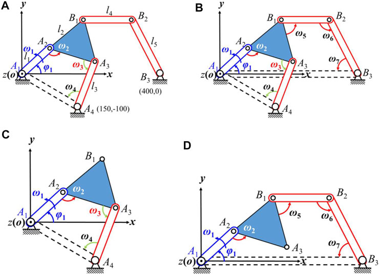
FIGURE 8. A planar 6-bar linkage. (A) Structure of a planar 6-bar linkage; (B) Two independent closed-chain 6-bar linkages; (C) A 4-bar linkage of closed chain; (D) Closed chain of a coupled 5-bar linkage.
Similarly, we get the loop equation of the second coupled 5-bar closed chain linkage (Figure 8 (d)) from Equation 28:
Rearranging this loop equation presents:
So the forward kinematics of the multiple closed chain linkage can be obtained by associating these double-loop Equations 33, 34:
where
We let the angular velocity of joint

TABLE 4. Structure parameters and initial conditions.
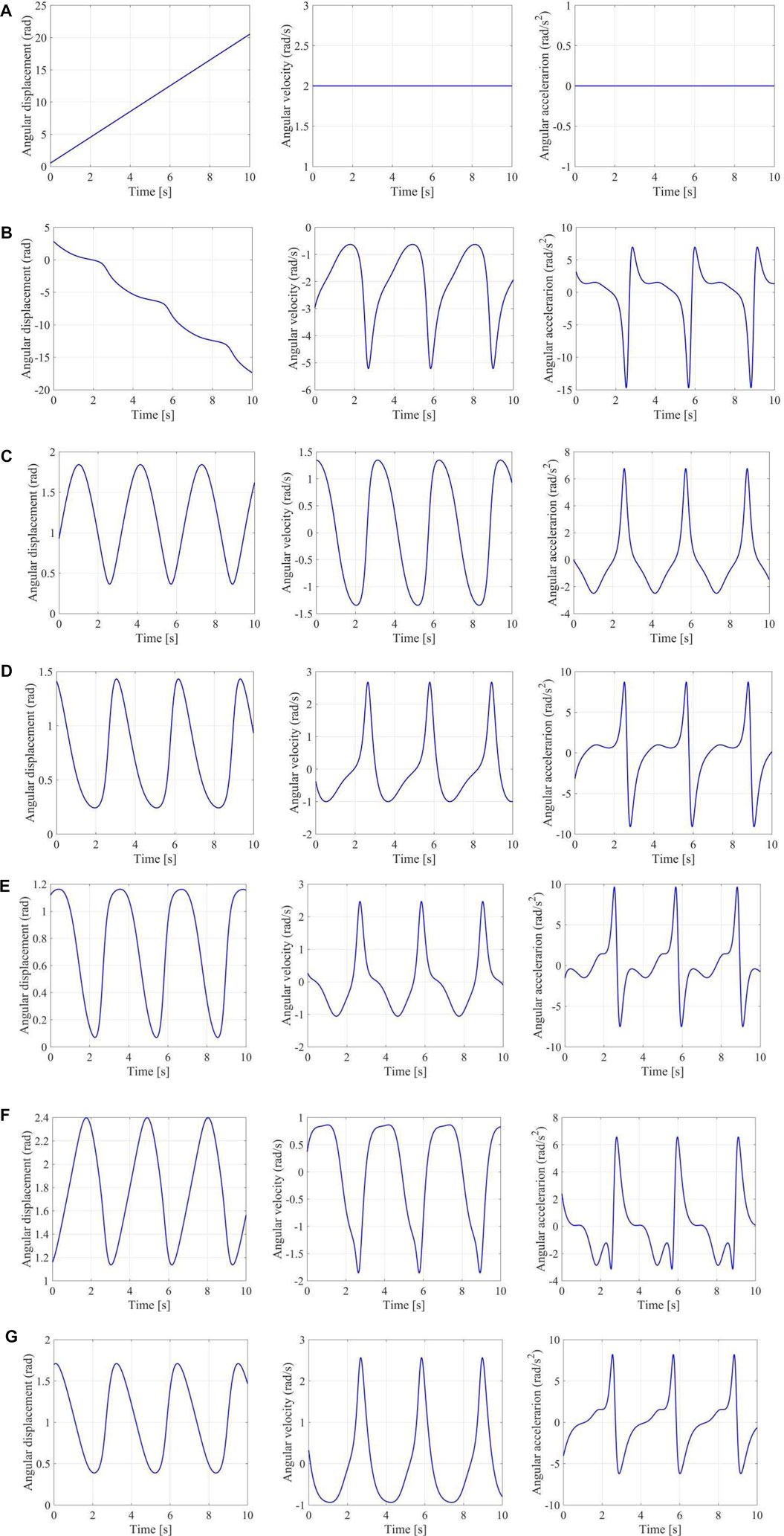
FIGURE 9. Forward kinematics of a multiple closed chain linkage. (A) Angular displacement, velocity, and acceleration of joint A1; (B) Angular displacement, velocity, and acceleration of joint A2; (C) Angular displacement, velocity, and acceleration of joint A3; (D) Angular displacement, velocity, and acceleration of joint A4; (E) Angular displacement, velocity, and acceleration of joint B1; (F) Angular displacement, velocity, and acceleration of joint B2; (G) Angular displacement, velocity, and acceleration of joint B3.
Kinematics of a Planar Mechanism of More Degrees of Freedom With Single Closed Chain
Figure 10 illustrates 1) a planar 5-bar linkage in series and 2) a 5-bar linkage of closed loop. The twist of the end effector of the 5-bar linkage in series can be gained by Equation 12:
where
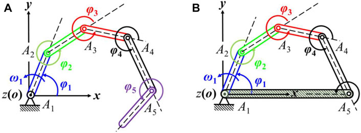
FIGURE 10. Planar 5-bar linkages. (A) A 5-bar linkage in series; (B) A 5-bar linkage of closed chain.
From Equation 12, we know that the kinematic chain forms a closed loop when the end effector is fixed with the frame (Figure 10B). Therefore, there must be
Then there is
Therefore, we get the forward kinematics of the closed-chain 5-bar linkage (Figure 10B):
where
Eq. 37 represents the forward velocity of the planar 5-bar mechanism of 2 degrees of freedom. In accordance to the numerical Eq. 32, 27, we obtain the forward displacement and acceleration of the mechanism with a single closed chain. We let the angular velocity of joint

TABLE 5. Initial conditions and structure parameters.
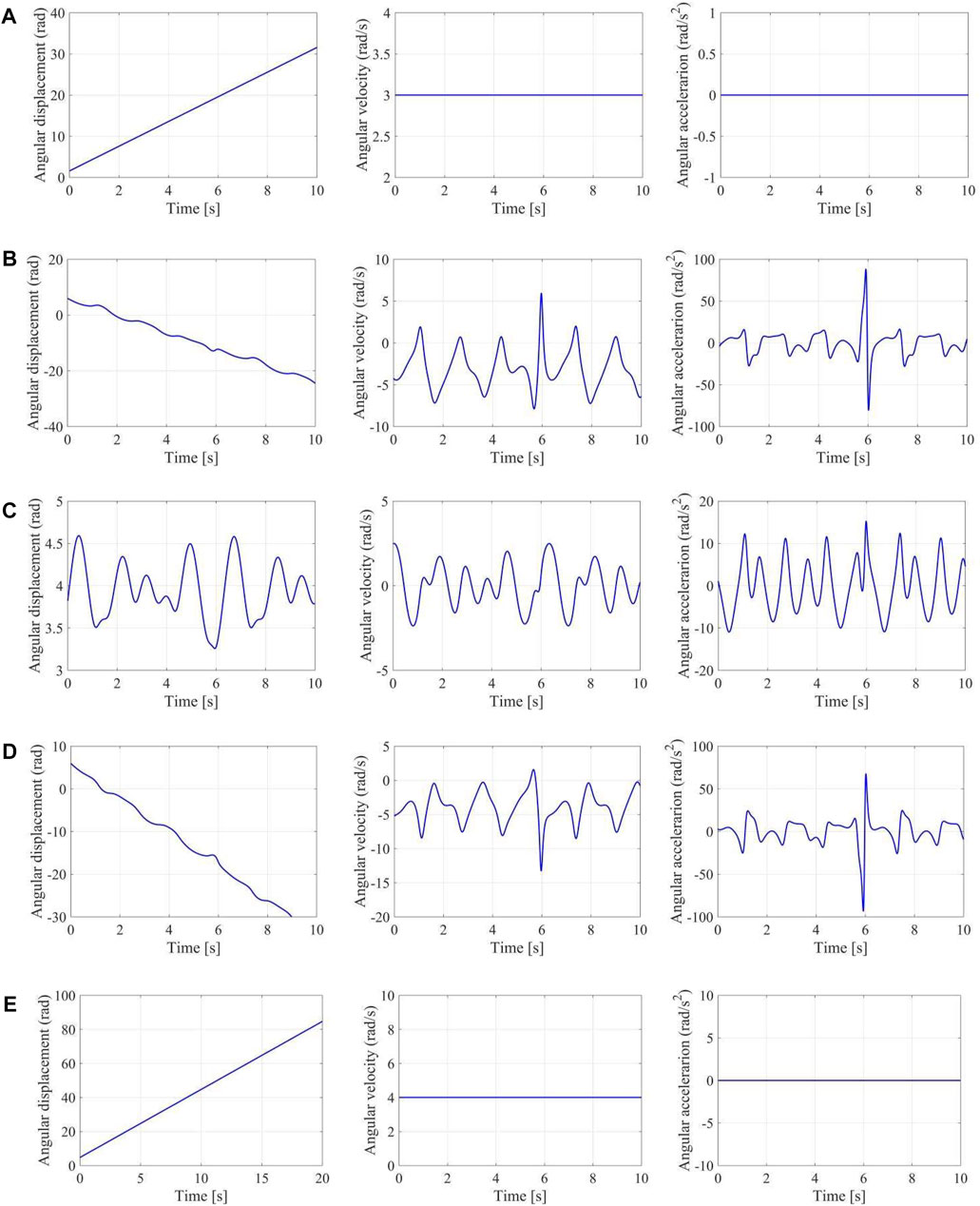
FIGURE 11. Forward kinematics of a 5-bar linkage. (A) Angular displacement, velocity, and acceleration of joint A1; (B) Angular displacement, velocity, and acceleration of joint A2; (C) Angular displacement, velocity, and acceleration of joint A3; (D) Angular displacement, velocity, and acceleration of joint A4; (E) Angular displacement, velocity, and acceleration of joint A5.
Conclusion
This paper proposed a method to investigate the displacement, velocity and acceleration of a mechanism in screw coordinates in a general systematic way. As the twist of an articulated rigid body includes the angular velocity and linear velocity, the corresponding displacements of all joints are obtained through one-order integration of the velocity solutions and the accelerations are represented by the first order numerical differential interpolation. Compared to the traditional methods in which the displacement parameters are the only variables that will surely lead to the second order differential interpolations for the accelerations, the advantages of this method is that both the forward and inverse kinematics of a mechanism can be expressed in a same way and only one-order differential interpolation is needed to get the acceleration and one-order integral is required to calculate the displacement. This method is validated by planar mechanisms in series, single closed loop and multiple closed loops. This method is particularly suitable for programming the computational software for forward and inverse kinematics of a mechanism, covering the velocity, displacement and acceleration. Although this paper discusses the kinematics of revolute jointed planar mechanisms, the same principles may apply to any spatial linkages.
Data Availability Statement
The original contributions presented in the study are included in the article/Supplementary Material, further inquiries can be directed to the corresponding author.
Author Contributions
methodology, J-SZ; software, S-TW; validation, J-SZ, S-TW; formal analysis, J-SZ; investigation, J-SZ, S-TW; resources, J-SZ; data curation, S-TW; writing—original draft preparation, J-SZ; writing—review and editing, J-SZ, S-TW; visualization, J-SZ, S-TW; supervision, J-SZ; project administration, J-SZ; funding acquisition, J-SZ All authors have read and agreed to the published version of the manuscript.
Funding
This research was supported by the Natural Science Foundation of China under Grant 51575291.
Conflict of Interest
The authors declare that the research was conducted in the absence of any commercial or financial relationships that could be construed as a potential conflict of interest.
Publisher’s Note
All claims expressed in this article are solely those of the authors and do not necessarily represent those of their affiliated organizations, or those of the publisher, the editors, and the reviewers. Any product that may be evaluated in this article, or claim that may be made by its manufacturer, is not guaranteed or endorsed by the publisher.
Supplementary Material
The Supplementary Material for this article can be found online at: https://www.frontiersin.org/articles/10.3389/fmech.2021.774814/full#supplementary-material
References
Amiri, A., and Mazaheri, H. (2020). Study on the Behavior of a Temperature-Sensitive Hydrogel Micro-channel via FSI and Non-FSI Approaches. Acta Mech. 231, 2799–2813. doi:10.1007/s00707-020-02673-z
Angeles, J. (1982). Spatial Kinematic Chains: Analysis, Synthesis, and Optimization. Berlin: Springer-Verlag, 55–76.
Barus, C. (1900). A Treatise on the Theory of Screws. Cambridge: Cambridge University Press, 1001–1003. doi:10.1126/science.12.313.1001
Brát, V., and Lederer, P. (1973). KIDYAN: Computer-Aided Kinematic and Dynamic Analysis of Planar Mechanisms. Mechanism Machine Theor. 8 (4), 457–467. doi:10.1016/0094-114X(73)90020-7
Chapelle, F., and Bidaud, P. (2004). Closed Form Solutions for Inverse Kinematics Approximation of General 6R Manipulators. Mechanism Machine Theor. 39 (3), 323–338. doi:10.1016/j.mechmachtheory.2003.09.003
Craig, J. (1986). Introduction to Robotics, Mechanics and Control. New York, Jan: Addison-Wesley, 33–137.
Dai, J. (2014). Screw Algebra and Lie Groups and Lie Algebras. 2nd Edition. Beijing: Higher Education Press, 123–140.
Davidson, J. K., and Hunt, K. H. (2004). Robots and Screw Theory: Applications of Kinematics and Statics to Robotics. New York: Oxford University Press, 56–78.
Duffy, J. (1996). Statics and Kinematics with Applications to Robotics. New York: Cambridge University Press, 46–78.
Faghidian, S. A., and Mohammad-Sedighi, H. (2020). Dynamics of Nonlocal Thick Nano-Bars. Eng. Comput. doi:10.1007/s00366-020-01216-3
García de Jalón, J., and Bayo, E. (1994). Kinematic and Dynamic Simulation of Multibody Systems: The Real-Time Challenge. New York, Jan: Springer-Verlag, 220–254.
Gough, V. E., and Whitehall, S. G. (1962). “Universal Tyre Test Machine,” Proceedings of the International Technical Congress FISITA. UK: Institution of Mechanical Engineers, 117.
Hunt, K. H. (1978). Kinematic Geometry of Mechanisms. New York, Jan: Oxford University Press, 66–85.
Kong, K., Chen, G., and Hao, G. (2019). Kinetostatic Modeling and Optimization of a Novel Horizontal-Displacement Compliant Mechanism. J. Mech. Robotics 11 (6), 1. doi:10.1115/1.4044334
Kong, X., He, X., and Li, D. (2018). A Double-Faced 6R Single-Loop Overconstrained Spatial Mechanism. J. Mech. robotics 10 (3). 031013 doi:10.1115/1.4039224
Kong, X., Yu, J., and Li, D. (2016). Reconfiguration Analysis of a Two Degrees-Of-Freedom 3-4R Parallel Manipulator with Planar Base and Platform1. J. Mech. Robotics 8 (17). 011019 doi:10.1115/1.4031027
McCarthy, J. M. (1990). An Introduction to Theoretical Kinematics. London, Mar: The MIT Press, 33–45.
McCarthy, J. M., and Soh, G. S. (2011). Geometric Design of Linkages. New York, Jan: Springer, 13–46.
Norton, R. L. (2004). Design of Machinery—An Introduction to the Synthesis and Analysis of Mechanisms and Machines. 3rd ed. New York, Jan: McGraw-Hill Companies, Inc., 30–81.
Saura, M., Segado, P., and Dopico, D. (2019). Computational Kinematics of Multibody Systems: Two Formulations for a Modular Approach Based on Natural Coordinates. Mechanism Machine Theor. 142 (12). 103602 doi:10.1016/j.mechmachtheory.2019.103602
Shen, H., Chablat, D., Zeng, B., Li, J., Wu, G., and Yang, T.-L. (2020). A Translational Three-Degrees-Of-Freedom Parallel Mechanism with Partial Motion Decoupling and Analytic Direct Kinematics. J. Mech. Robotics 12 (2). 021112 doi:10.1115/1.4045972
Shigley, J. E., and Uicher, J. J. (1980). Theory of Machines and Mechanisms. New York, Jan: McGraw-Hill Companies, Inc.
Stewart, D. (1965). A Platform with Six Degrees of freedom. Proc. Inst. Mech. Eng. 180 (1), 371–386. doi:10.1243/pime_proc_1965_180_029_02
Waldron, K. J., and Kinematics, G. L. Kinzel. (2004). Dynamics, and Design of Machinery. Hamilton PrintingNew York: John Wiley & Sons, 5–16.
Wu, J., Gao, Y., Zhang, B., and Wang, L. (2017). Workspace and Dynamic Performance Evaluation of the Parallel Manipulators in a spray-painting Equipment. Robotics and Computer-Integrated Manufacturing 44 (4), 199–207. doi:10.1016/j.rcim.2016.09.002
Wu, J., Li, T., Wang, J., and Wang, L. (2013). Performance Analysis and Comparison of Planar 3-DOF Parallel Manipulators with One and Two Additional Branches. J. Intell. Robot Syst. 72 (1), 73–82. doi:10.1007/s10846-013-9824-8
Wu, J., Wang, J., Wang, L., and Li, T. (2009). Dynamics and Control of a Planar 3-DOF Parallel Manipulator with Actuation Redundancy. Mechanism and Machine TheoryApr 44 (4), 835–849. doi:10.1016/j.mechmachtheory.2008.04.002
Yang, T.-L., Liu, A., Shen, H., Hang, L., and Jeffery Ge, Q. (2018). Composition Principle Based on Single-Open-Chain Unit for General Spatial Mechanisms and its Application-In Conjunction with a Review of Development of Mechanism Composition Principles. J. Mech. Robotics 10 (5). 051005 doi:10.1115/1.4040488
Zhao, D.-J., Zhao, J.-S., and Yan, Z.-F. (2016). Planar Deployable Linkage and its Application in Overconstrained Lift Mechanism. J. Mech. Robotics 8 (29). 021022 doi:10.1115/1.4032096
Keywords: kinematics, numerical algorithm, planar open-chain linkage, closed-chain linkage, articulated joint
Citation: Zhao J-S and Wei S-T (2021) Kinematics of Articulated Planar Linkages. Front. Mech. Eng 7:774814. doi: 10.3389/fmech.2021.774814
Received: 13 September 2021; Accepted: 04 November 2021;
Published: 14 December 2021.
Edited by:
Hamid M. Sedighi, Shahid Chamran University of Ahvaz, IranReviewed by:
S. Ali Faghidian, Islamic Azad University, IranAkihiro Nakatani, Osaka University, Japan
Copyright © 2021 Zhao and Wei. This is an open-access article distributed under the terms of the Creative Commons Attribution License (CC BY). The use, distribution or reproduction in other forums is permitted, provided the original author(s) and the copyright owner(s) are credited and that the original publication in this journal is cited, in accordance with accepted academic practice. No use, distribution or reproduction is permitted which does not comply with these terms.
*Correspondence: Jing-Shan Zhao, amluZ3NoYW56aGFvQG1haWwudHNpbmdodWEuZWR1LmNu