 John Valerian Corda1
 B. Satish Shenoy1
 Leslie Lewis2
 Prakashini K.3S. M. Abdul Khader4
 Kamarul Arifin Ahmad5
 Mohammad Zuber1*
- 1Department of Aeronautical and Automobile Engineering, Manipal Institute of Technology, Manipal Academy of Higher Education, Manipal, India
- 2Department of Paediatrics, Kasturba Medical College and Hospital, Manipal, India
- 3Department of Radio Diagnosis, Kasturba Medical College and Hospital, Manipal, India
- 4Department of Mechanical and Manufacturing Engineering, Manipal Institute of Technology, Manipal Academy of Higher Education, Manipal, India
- 5Department of Aerospace Engineering, Universiti Putra Malaysia, Seri Kembangan, Selangor, Malaysia
Background and objective: Causes for nasal airway obstruction (NAO) are many but septum deviation is the most prevalent etiology. A deviated septum affects the airflow dynamics in the human nasal cavity, which in turn affects the physiological functions of the nasal cavity like heating, humidification, and filtration capabilities. The present study investigates and compares the airflow patterns in a healthy nasal cavity to a septal deviated nasal cavity.
Methods: Two nasal airway models are considered and compared in this study. One with a septal deviation and the second with a healthy patent nasal cavity. Airflow analysis is carried out by developing the CT scans into 3D models using Materialise MIMICS (Materialise, Ann Arbor, MI), and then using the FLUENT solver of ANSYS 2020R2. The simulations are carried out for airflows ranging in laminar and turbulent flows using the SST k-ω turbulence model. Polyhedral meshes are used and the mesh check using Grid Convergence Index studies is adopted.
Results: The pressure and velocity profiles are assessed for a wide range of mass flow rates. The results indicate a turbulent flow pattern for mass flow rates over 15 LPM. The velocity profiles show aberrated flow profiles in a septal deviated nasal cavity where the peak velocity is observed at the mid-nasal region rather than the nasal valve region. There was a 38% to 55% higher nasal resistance in the septal deviated nasal cavity as compared to a normal and healthy nasal cavity. The pressure drop in the septal deviated nasal cavity is higher by 60%–120% when compared to a healthy nasal cavity.
Conclusion: The septal deviated nasal cavity greatly affects the nasal airflow distribution resulting in higher velocities in the mid-nasal region, increased pressure drop and higher nasal resistance. Hence the NAO with septal deviation has to be rectified with proper surgical procedures.
Introduction
The human nasal cavity is crucial in warming and moisturizing the air that is inspired. In addition, the inspired air is cleared of fine dust particles and other unwanted particles by the upper nasal cavity before it reaches the lower airways and then into the lungs (Sobiesk and Munakomi, 2021). The inspired air in the nasal cavity undergoes two abrupt turns, the first at the nasal valve region into the mid-nasal region, and the second at the nasopharynx region where it is diverted to the lower respiratory region before entering the lungs. The nasal cavity is portioned into two nearly equal parts with separate compartments by the nasal septum. Though ideally, the septum should divide the nasal cavity into two halves, it rarely happens that both sides of the nasal cavity are exactly symmetrical. It is said that nearly 80% of people do not have a symmetric nasal cavity. A deviated septum is one of the most common nasal conditions (Fettman et al., 2009). Abnormal septal growth can be attributed to birth trauma or early-life microfractures (Holt, 1999). A study showed that around 20% of newborns in India had nasal cavities with septal deviation (Harugop et al., 2012).
Obstruction in nasal cavities is a common complaint given by many people. Some of the major causes of nasal obstructions are enlarged concha bullosa, chronic rhinosinusitis, allergic rhinitis, nasal septal deviation, hypertrophied inferior turbinate, nasal polyps, choanal atresia (Bhandary and Kamath P, 2009; Constantian and Clardy, 1996; Lee, 2013; Maturo and Lopez, 2011). Deviated septum may result in enlarged turbinates which alter the normal airflow phenomenon in the nose. The nasal septum acts as a centreline support for the nasal cavity, in addition to providing a space between nasal walls and the centreline for the passage of air. A straight septum assures the airflow is smooth and laminar thereby performing the physiological functions of the nose effectively (Aziz et al., 2014). On the other hand, a deviated septum may result in elevated nasal resistance, snoring and the aesthetic appearance of the nose (Hsia et al., 2014). Common symptoms include nose bleedings, face pain, obstructed nostrils, noisy breathing during sleeping and preferential sleep at one particular side (Mayo Clinic, 2021).
Septal deviation can be corrected by a surgical procedure called septoplasty (Thomas et al., 2016; Ketcham and Han, 2010). However, septoplasty may result in complications like Hemorrhage/septal hematoma, perforations, deformations in the nasal structure like saddle nose, nasal tip ptosis, hyposmia, endocranial complications, and ocular complications to name a few (Dąbrowska-Bień et al., 2018). In silico simulations using computational fluid dynamics (CFD) have emerged as a faithful tool to capture and analyze airflow inside the nasal cavity. Researchers have confidently used CFD to predict the airflow dynamics, particle depositions, and thermal conditioning studies in the nasal cavity particularly in cases where practically constructing the nasal cavity and experimentation is found to be not viable economically (Inthavong et al., 2019; Zuber et al., 2020; Keeler et al., 2016; Pless et al., 2004). In addition to this virtual surgeries are also planned using CFD (Vanhille et al., 2018; Frank-Ito et al., 2019b).
Studies on septal deviations have been studied by researchers in the past (Chen et al., 2009; Liu et al., 2012; Frank-Ito et al., 2019a). This study attempts to add knowledge to the already existing studies by investigating the airflow dependence on the anatomical variations that are found between a healthy nasal cavity and a septal deviated nasal cavity. Further, the relation between the airway geometry and the airflow parameters is studied. The study employs a range of flow rates at the inlet from 5 LPM to 35 LPM which depicts normal breathing and light exercise conditions (Subramaniam et al., 1998). The flow range considered in this study additionally covers both the laminar and turbulent flow regimes in the nasal cavity. The influence of septal deviation on nasal airflows is evaluated and compared with a healthy nasal cavity. This study employs two nasal cavities, one with a septal deviation and the other is a normal and healthy nasal cavity. The CT scans are used to generate a 3D model of these nasal cavities, which are then exported to CATIA V5, followed by a airflow simulation using ANSYS FLUENT 2020 R2.
Materials and methods
Reconstruction of the nasal cavity
Institutional ethical clearance has been obtained for this study further to which the CT scans of the adult nasal cavities are procured from the Department of Radio-Diagnosis, Kasturba Medical College, Manipal, India. Two cases of CT scans are procured, one is of the patient with the nasal septum and the other is of a healthy nasal cavity without any reported breathing difficulties. The procured CT scans are anonymized before proceeding to the model generation. The details of CT scans are given in Table 1 and the slice increments are below 2 mm for the selected scans to capture the intricate nasal geometry (Bailie et al., 2006). In line with many of the previous works by researchers, only the main nasal airway is constructed and the sinus is not included in this simulation (Zubair et al., 2013b; Xi et al., 2012; Inthavong et al., 2019).

TABLE 1. Details of CT scans.
An image processing software MIMICS (Materialise, Ann Arbor, MI, United States) is used to generate a 3D model from the CT scans. Utilizing the thresholds between −1024 HU and −444 HU, segmentation is performed. Segmentation is carried out slice by slice thereby building the nasal cavity which is then exported to 3-MATIC (Materialise, Ann Arbor, MI, United States) where the file is saved in .STL format. This file is then exported to CATIA V5 to generate a solid airway which is saved in .stp format. This file in .stp format can be simulated for flow in ANSYS FLUENT 2020 R2.
Flow field equations
Continuity and momentum equations are used to simulate the flow in the nasal cavity. The energy equation is not used as the temperature effects are not considered. These equations are shown in equations Eqs 1, 2.
Where “u” represents air velocity, “ρ” denotes fluid density and
Reynolds Average Navier Stokes equations are used to characterize the incompressible and viscous 3D fluid flow. SST k-ω model is used which is a two-equation shear stress transport equation. This was developed by Menter (1994) and has been widely used by many researchers in the past (Mylavarapu et al., 2009; Zubair et al., 2013b).
Meshing
The meshing of the generated nasal cavities is executed using the polyhedral meshing technique with six prism layers at the nasal wall boundaries and ensuring a y+ value of less than 1. Maximum skewness is limited to a value of 0.7. Three meshing iterations namely the coarse (N3), medium (N2), and fine (N1) meshing are used for grid convergence studies. A sample meshing at mid nasal section plane is shown in Figure 1.
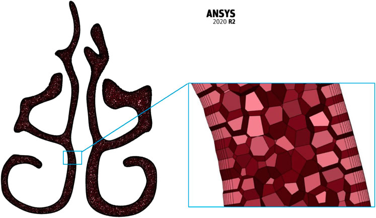
FIGURE 1. Mesh information.
Boundary conditions and simulation setup
It is assumed that the nasal wall is rigid and non-slip (Ishikawa et al., 2009; Brüning et al., 2020). A mass flow rate equivalent to a particular air intake in liters per minute is applied at the nostril inlets. The range of flows considered in this study is from 5 LPM to 30 LPM which are in laminar and turbulent flow regimes (Zamankhan et al., 2006; Frank-Ito et al., 2019b; Garcia et al., 2007). As a general norm, for adult nasal cavities, any flow below 15 LPM is considered laminar in nature and over 15 LPM turbulent flow is considered to be governing. For the nasopharynx, an “outflow” boundary condition is considered which assumed a fully developed flow. The presence of a mucus layer and nasal hair is not included in this simulation. The properties of the fluid (air) used in this calculation are the density and dynamic viscosity of 1.225 kg/m3 and 1.7894 × 10⁻⁵ kg/(ms) respectively.
The governing equations are discretized over the control volume. Integrating these discretized equations gives the set of equations in algebraic form. The simulations were executed using CFD solver ANSYS FLUENT 2020 R2. The SIMPLE algorithm was chosen to relate the velocity and pressure corrections. Second-order schemes for momentum, turbulent kinetic energy, and specific dissipation rate are used for higher accuracy and the convergence criteria of four orders of magnitude were adopted.
Results
Comparison of nasal cavities
To efficiently visualize the airflow at different locations, and to compare the area variations, the nasal cavity is marked with different planes where the values can be extracted as shown in Figure 2.
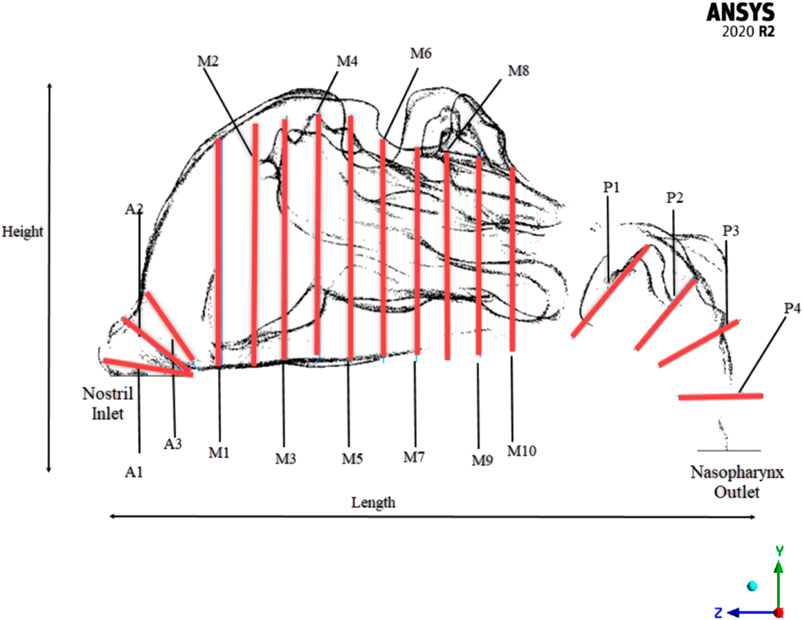
FIGURE 2. Cross-sectional planes in the adult nasal cavity.
Two nasal cavities are considered in this study, one with a septal deviation and the other with a healthy patent nasal cavity (Keyhani et al., 1995; Cheng et al., 1996; Subramaniam et al., 1998; Wen et al., 2008; Xi et al., 2012; Garcia et al., 2016). As seen in Figure 3, the nasal cavities’ cross-sectional areas are plotted against their normalized length from the anterior nose tip. The septal deviation in Patient P01 is identified from the CT scans as shown in Figure 4.
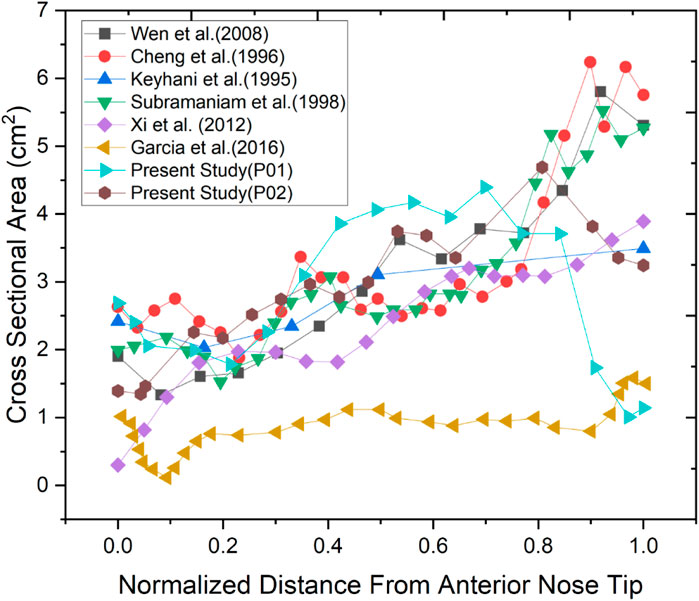
FIGURE 3. Comparison of cross-sectional areas with the literature.
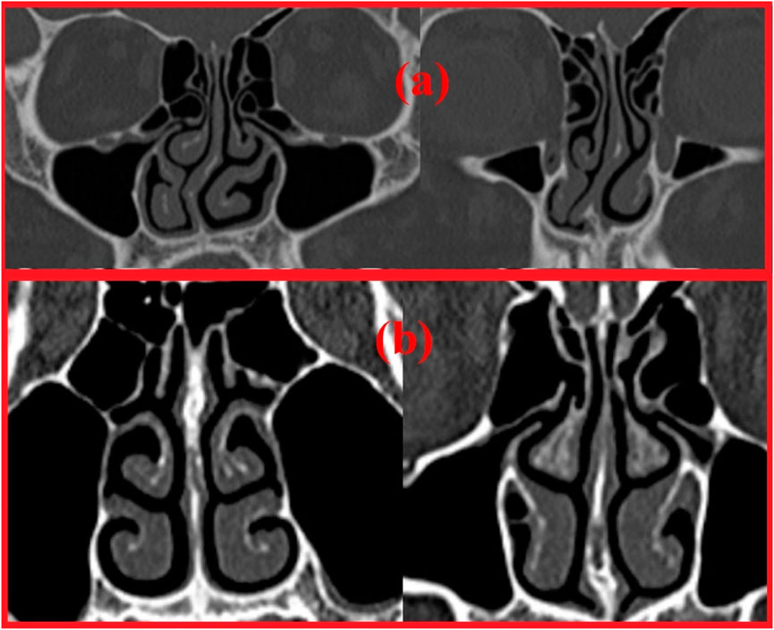
FIGURE 4. Coronal section showing (A) Deviated septum in P01 (B) Healthy nasal cavity in P02.
The normalized distance from the anterior tip of the nostrils is used to compare the cross-sectional areas. As plotted in Figure 5. The highlighted region is the nasal valve region, which is the narrowest and most constricted region in the nasal cavity. Figure 5 shows that the mid-nasal region has the smallest cross-sectional area for the septal deviated nasal cavity. This has a significant impact on the nasal cavity’s airflow dynamics, which affects how the nasal cavity physiologically functions, such as the filtration of dust particles and the heat conditioning of the inspired air.
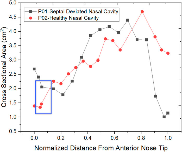
FIGURE 5. Cross-Sectional area Comparison.
The effective diameter at different locations in the nasal cavity is calculated and compared for the nasal cavities. The effective diameter is indicated in Table 2 which shows that the effective diameter of the septal deviated nasal cavity is 88% that of the normal nasal airway. Nasal resistance is influenced by the effective diameter (Hey and Price, 1982).
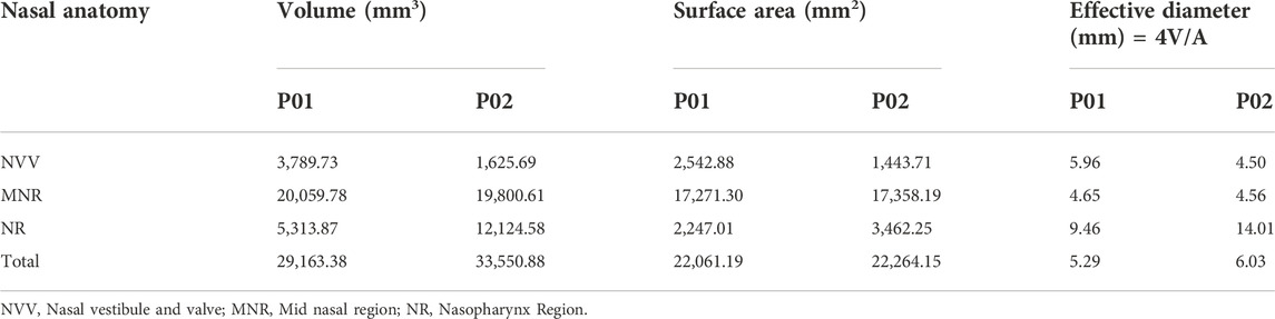
TABLE 2. Effective diameter.
The hydraulic diameter is equal to four times the area divided by the perimeter. Table 3 shows the hydraulic diameter calculated and indicated. The hydraulic diameter affects the Reynolds Number Calculations, which indicate whether the flow is laminar or turbulent.
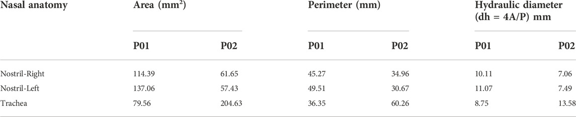
TABLE 3. Hydraulic diameter.
Meshing results
The meshing of the nasal cavities included three meshing stages with coarse, medium, and fine meshes which are indicated in Table 4. The mesh generated is in the asymptotic range of convergence and can be concluded to be independent of any further mesh refinement.
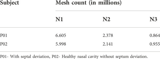
TABLE 4. Mesh details.
The grid convergence index study in Table 5 shows a numerical uncertainty of 13.551% and 0.174% respectively for the mesh generated for P01 and P02 were observed. Celik et al. (2008), explained the GCI calculation method using the discretization error estimation technique explained by Richardson and Glazebrook (1911).

TABLE 5. GCI results.
Reynolds number, nasal resistance, and pressure drop
The Reynolds numbers are calculated for the septal deviated and normal nasal cavities and reported in Table 6.
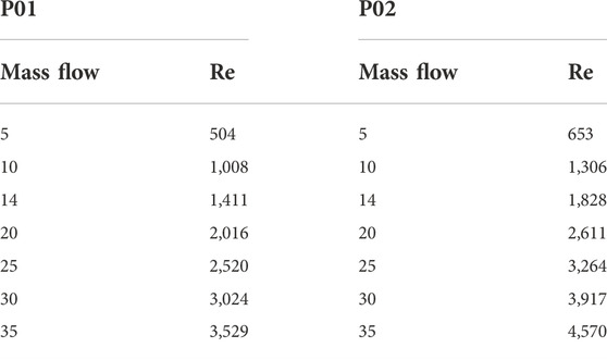
TABLE 6. Calculated reynolds number at the nostril inlet for variable flow rates.
Reynolds number indicates the nature of the flow where a value less than 2,000 is considered laminar, 2,000–2,300 is transitional flow and above 2,300 the flow becomes turbulent. From Table 6 it can be seen that the airflow in the nasal cavity is laminar up to 15 LPM and over this, the flow becomes turbulent in nature.
Nasal resistance for the two cases mentioned in this study is listed in Table 7. During the breathing process, there is a certain quantum of obstruction is generated which is known as nasal resistance. It is calculated by the ratio of pressure difference across the nasal cavity to the mass flow rate (ΔP/Q). It can be seen from the table that the nasal resistance values are comparable to work done by previous researchers for a healthy nasal cavity.

TABLE 7. Nasal resistance across the nasal cavity.
From Table 7, it can be seen that the nasal resistance in the septal deviated nasal cavity is higher when compared to a healthy nasal cavity. The total nasal resistance indicates the degree of nasal obstruction during breathing and provides an overall assessment of nasal functioning. A study has shown the limited link between the minimum cross-sectional area and perceived nasal patency may be because airway constrictions are not always the only cause of nasal resistance (Garcia et al., 2016). This study however shows that there is a decrease in nasal resistance in a healthy nasal cavity attributed to the ease of breathing.
The Figure 6 indicates the pressure drop plotted against the mass flow rates for the nasal cavities studied. Additionally, the work done by researchers in the past is also plotted (Wen et al., 2008; Weinhold and Mlynski, 2004).
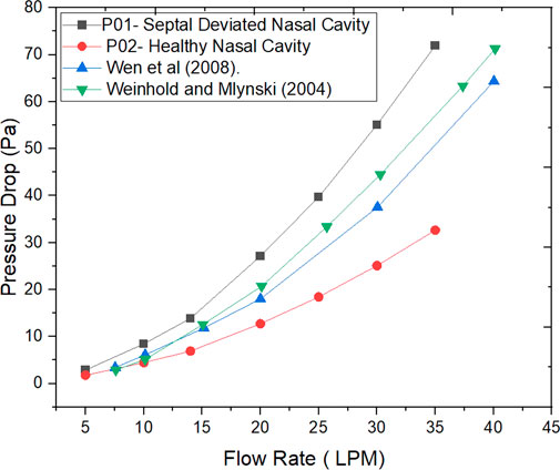
FIGURE 6. Pressure drop for different inhalation flow rates.
Velocity profiles and wall shear stress
The velocity profiles are plotted only for a mass flow rate of 14 LPM for the two nasal cavities. The Figure 7 shows maximum velocity locations at the nasal valve region for the healthy nasal cavity which is the general trend observed by many researchers. But for the septal deviated nasal cavity, the peak velocity is observed in the mid-nasal region as well as in the nasopharynx region which is abnormal in nature.
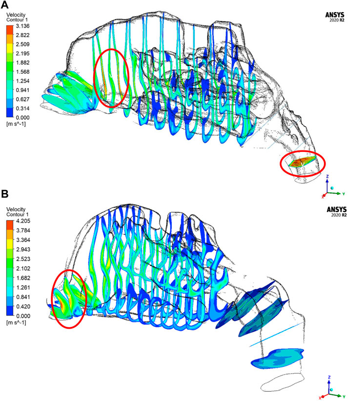
FIGURE 7. Velocity contours in (A) P01-Septal deviated nasal cavity (B) P02- Healthy nasal cavity.
As per the literature, the peak velocity is expected at the nasal valve region as it is the location with the least cross-sectional area (Segal et al., 2008; Inthavong et al., 2019). In general, the mid-nasal region experiences lower velocity in both the nasal cavities considered in this study. Since the nasal valve’s primary function is to constrain and congregate the airflow produced in the nasal cavity, it must always be functioning at a high velocity. Because the middle turbinate has the largest surface area, it has less vascular tissue density and is less visible in nasal airflow patterns. To understand the velocity distribution across the nasal cavity, the maximum velocity values are potted along the normalized length of the nasal cavity. The values plotted in Figure 8 are for two mass flow rate values that are for 14 LPM and 35 LPM.
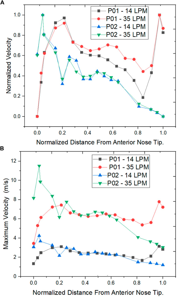
FIGURE 8. Velocity distribution across the normalized distance from anterior nose tip (A) Normalized Velocity (B) Maximum Velocity (m/s).
The normalized velocity plot in Figure 8A indicates that the peak velocity in the septal deviated nasal cavity is observed at the mid-nasal and the nasopharynx region indicating an unusual flow pattern when compared to a healthy nasal cavity.
The wall shear stress distribution along the length of the nasal cavity is plotted for the two nasal cavities at 14 LPM and 35 LPM as indicated in Figure 9.
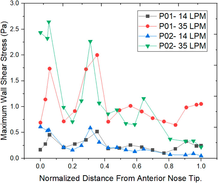
FIGURE 9. Wall shear stress comparision along length at different planes.
The air passing through the nasal cavity continuously applies shearing frictional forces to the nasal wall which is called wall shear stress. The wall shear stress showed a peak value in the nasal valve region which is in agreement with the literature (Doorly et al., 2008). The Healthy nasal cavity experiences a higher wall shear stress when compared to a septal deviated nasal cavity. The overall patterns of wall shear stress show higher wall shear stress along the anterior regions of the inferior turbinate which is in line with the literature (Bailie et al., 2009).
Discussion
The septal deviation is one of the most commonly encountered nasal airway obstructions. The deviated septum influences the physiological functions of the nasal cavity which can be seen in this study where the nasal airflows are compared between a septal deviated and a healthy nasal cavity. The Reynolds number calculations show that the airflow is laminar for flow rates below 15 LPM, and as the mass flow rate at the nostril inlets increases beyond 15 LPM the flow tends to become turbulent in nature. These findings are in line with the findings of previous researchers (Inthavong et al., 2019; Chen et al., 2009). However, a comparison between the nasal cavities used in this study shows a higher Reynolds number in a healthy nasal cavity when compared to the septal deviated nasal cavity.
The values of nasal resistance indicate comparatively higher values in a septal deviated nasal cavity when compared to a healthy nasal cavity. Interestingly the nasal resistance values in septal deviated nasal cavities are greater than the healthy nasal cavity by a range from 38% to 50% for mass flows below 15 LPM, but as the mass flow rate increases the nasal resistance values increase beyond 50%. This indicates that nasal resistance increases as breathing changes from sedentary to exercising conditions. Nasal resistance across the nasal cavity greatly depends on the nasal anatomy (Ohki et al., 1991). Pressure drop has been traditionally used to validate CFD solutions where the pressure difference is taken between the nostril inlets and the nasopharynx outlets (Weinhold and Mlynski, 2004). Pressure drop is considered to highly influence nasal patency (Ottaviano and Fokkens, 2016). Higher values of pressure drop are observed in the septal deviated nasal cavity as compared to a healthy nasal cavity.
The velocity profiles indicate an abnormal velocity distribution trend across the septal deviated nasal cavity which is contrary to the healthy nasal cavity where a peak velocity is observed at the nasal valve region. The nasal valve region is the most constricted in the nasal cavity, which results in the highest velocity due to air accelerating in this region (Segal et al., 2008). Following the nasal valve, there is an abrupt increase in the cross-sectional area resulting in a decrease in the velocity (Croce et al., 2006). Septal deviated nasal cavity experiences peak velocities at the mid-nasal region and the nasopharynx region which indicates an aberrated flow pattern. This may consequence in the thermal conditioning and the filtration capabilities of the nasal cavity.
Wall shear stress (WSS) is the friction force that is generated when the air moves inside the nasal cavity which permits the heat and mass transfer between the air and the nasal cavity. Local concentrations of the stresses would result in irritating blood vessels (Wen et al., 2008). The results show higher wall shear stress at the nasal valve region for the normal nasal cavity which is the general trend observed, but the septal deviated nasal cavity experiences the highest WSS in the mid-nasal region.
Limitations and future work
Only one nasal cavity each of septal deviation and a healthy subject are considered for this study. This study can be further improvised by improving the sample size considered. This study is performed for steady-state conditions, and future work can consider transient simulations. Future work shall include thermal studies comparison due to airflow variations resulting from septal deviation. Future studies can also include the comparison of the effects of inspiration and expiration on nasal airflows.
Conclusion
Septal deviation which is one of the major causes of NAO is studied by comparing the airflow patterns in a healthy airway and a septal deviated nasal airway. In this study, the CT scans of a septal deviated nasal cavity and a healthy normal nasal cavity were used to develop 3D models and carry out airflow analysis for a range of 5 LPM–35 LPM indicating resting breathing and light exercising conditions respectively. The anatomy is compared which shows aberrated cross-sectional area patterns in a septal deviated nasal cavity where the most constricted area is at the mid-nasal region which is contrary to the healthy nasal cavity in which the nasal valve region is most constricted. The velocity patterns show a peak velocity at the mid-nasal region in the septal deviated nasal cavity which affects its physiological functions. The septal deviated nasal cavity projected higher nasal resistance in comparison to the healthy nasal cavity, higher by 38%–55%. The pressure drop values were higher by 60%–120% in the septal deviated nasal cavity as against the healthy nasal cavity. Hence it is implied that the NAO with septal deviation has to be effectively dealt with proper nasal procedures to relieve the airway and allow for the smooth flow of air.
Data availability statement
The original contributions presented in the study are included in the article/Supplementary Material, further inquiries can be directed to the corresponding author.
Ethics statement
The ethical clearance (IEC 416/2020) for this study is obtained from Kasturba Medical College Manipal.
Author contributions
JC and MZ—Conceptualization of the project. JC, MZ, and KA—Developing methodology and modeling of the work. PK and LL—Identifying CT scans, and checking for patent nasal cavities. JC and MZ—Analysis and processing data. BS, MZ, and SK—Supervision of project. JC, MZ, BS, and SK—Manuscript writing, reviewing, editing.
Acknowledgments
The authors would like to thank the Department of Aeronautical and Automobile Engineering, Manipal Institute of Technology, Manipal Academy, Manipal for the computing resources provided to carry out this work.
Conflict of interest
The authors declare that the research was conducted in the absence of any commercial or financial relationships that could be construed as a potential conflict of interest.
Publisher’s note
All claims expressed in this article are solely those of the authors and do not necessarily represent those of their affiliated organizations, or those of the publisher, the editors and the reviewers. Any product that may be evaluated in this article, or claim that may be made by its manufacturer, is not guaranteed or endorsed by the publisher.
Abbreviations
CFD, Computational fluid dynamics; CT, Computerized tomography; CATIA, Computed aided three-dimensional interactive application; FLUENT, Flow oriented logistics upgrade for enterprise networks; GCI, Grid convergence index; HU, Hounsfield unit; IEC, Institutional ethical clearance; LPM, Litres per minute; NAO, Nasal airway obstruction; Re, Reynolds number; SIMPLE, Semi-implicit method for pressure linked equations; WSS, Wall shear stress.
References
Aziz, T., Biron, V. L., Ansari, K., and Flores-Mir, C. (2014). Measurement tools for the diagnosis of nasal septal deviation: a systematic review. J. Otolaryngol. - Head Neck Surg. 43, 11. doi:10.1186/1916-0216-43-11
Bailie, N., Hanna, B., Watterson, J., and Gallagher, G. (2009). A model of airflow in the nasal cavities: implications for nasal air conditioning and epistaxis. Am. J. Rhinol. Allergy 23, 244–249. doi:10.2500/ajra.2009.23.3308
Bailie, N., Hanna, B., Watterson, J., and Gallagher, G. (2006). An overview of numerical modelling of nasal airflow. Rhinology 44, 53–57.
Bhandary, S. K., and Kamath P, S. D. (2009). Study of relationship of concha bullosa to nasal septal deviation and sinusitis. Indian J. Otolaryngol. Head. Neck Surg. 61, 227–229. doi:10.1007/s12070-009-0072-y
Brüning, J., Hildebrandt, T., Heppt, W., Schmidt, N., Lamecker, H., Szengel, A., et al. (2020). Characterization of the airflow within an average geometry of the healthy human nasal cavity. Sci. Rep. 10, 3755. doi:10.1038/s41598-020-60755-3
Celik, I. B., Ghia, U., Roache, P. J., Freitas, C. J., Coleman, H., and Raad, P. E. (2008). Procedure for estimation and reporting of uncertainty due to discretization in CFD applications. J. Fluids Eng. 130, 078001. doi:10.1115/1.2960953
Chen, X. B., Lee, H. P., Chong, V. F. H., and Wang, D. Y. (2009). Assessment of septal deviation effects on nasal air flow: A computational fluid dynamics model. Laryngoscope 119, 1730–1736. doi:10.1002/lary.20585
Cheng, Y. S., Yeh, H. C., Guilmette, R. A., Simpson, S. Q., Cheng, K. H., and Swift, D. L. (1996). Nasal deposition of ultrafine particles in human volunteers and its relationship to airway geometry. Aerosol Sci. Technol. 25, 274–291. doi:10.1080/02786829608965396
Constantian, M. B., and Clardy, R. B. (1996). The relative importance of septal and nasal valvular surgery in correcting airway obstruction in primary and secondary rhinoplasty. Plastic Reconstr. Surg. 98, 38–54. doi:10.1097/00006534-199607000-00007
Croce, C., Fodil, R., Durand, M., Sbirlea-Apiou, G., Caillibotte, G., Papon, J.-F., et al. (2006). In vitro experiments and numerical simulations of airflow in realistic nasal airway geometry. Ann. Biomed. Eng. 34, 997–1007. doi:10.1007/s10439-006-9094-8
Dąbrowska-Bień, J., Skarżyński, P. H., Gwizdalska, I., Łazęcka, K., and Skarżyński, H. (2018). Complications in septoplasty based on a large group of 5639 patients. Eur. Arch. Otorhinolaryngol. 275, 1789–1794. doi:10.1007/s00405-018-4990-8
Doorly, D. J., Taylor, D. J., and Schroter, R. C. (2008). Mechanics of airflow in the human nasal airways. Respir. Physiology Neurobiol. 163, 100–110. doi:10.1016/j.resp.2008.07.027
Fettman, N., Sanford, T., and Sindwani, R. (2009). Surgical management of the deviated septum: techniques in septoplasty. Otolaryngol. Clin. North Am. 42, 241–252. doi:10.1016/j.otc.2009.01.005
Frank-Ito, D. O., Carpenter, D. J., Cheng, T., Avashia, Y. J., Brown, D. A., Glener, A., et al. (2019a). Computational analysis of the mature unilateral cleft lip nasal deformity on nasal patency. Plast. Reconstr. Surg. Glob. Open 7, e2244. doi:10.1097/GOX.0000000000002244
Frank-Ito, D. O., Kimbell, J. S., Borojeni, A. A. T., Garcia, G. J. M., and Rhee, J. S. (2019b). A hierarchical stepwise approach to evaluate nasal patency after virtual surgery for nasal airway obstruction. Clin. Biomech. 61, 172–180. doi:10.1016/j.clinbiomech.2018.12.014
Garcia, G. J. M., Bailie, N., Martins, D. A., and Kimbell, J. S. (2007). Atrophic rhinitis: a CFD study of air conditioning in the nasal cavity. J. Appl. Physiology 103, 1082–1092. doi:10.1152/japplphysiol.01118.2006
Garcia, G. J. M., Hariri, B. M., Patel, R. G., and Rhee, J. S. (2016). The relationship between nasal resistance to airflow and the airspace minimal cross-sectional area. J. Biomech. 49, 1670–1678. doi:10.1016/j.jbiomech.2016.03.051
Harugop, A. S., Mudhol, R. S., Hajare, P. S., Nargund, A. I., Metgudmath, V. V., and Chakrabarti, S. (2012). Prevalence of nasal septal deviation in new-borns and its precipitating factors: A cross-sectional study. Indian J. Otolaryngol. Head. Neck Surg. 64, 248–251. doi:10.1007/s12070-011-0247-1
Hey, E. N., and Price, J. F. (1982). Nasal conductance and effective airway diameter. J. Physiol. 330, 429–437. doi:10.1113/jphysiol.1982.sp014349
Holt, G. R. (1999). Biomechanics of nasal septal trauma. Otolaryngol. Clin. North Am. 32, 615–619. doi:10.1016/s0030-6665(05)70159-6
Hsia, J. C., Camacho, M., and Capasso, R. (2014). Snoring exclusively during nasal breathing: a newly described respiratory pattern during sleep. Sleep. Breath. 18, 159–164. doi:10.1007/s11325-013-0864-x
Inthavong, K., Ma, J., Shang, Y., Dong, J., Chetty, A. S. R., Tu, J., et al. (2019). Geometry and airflow dynamics analysis in the nasal cavity during inhalation. Clin. Biomech. 66, 97–106. doi:10.1016/j.clinbiomech.2017.10.006
Ishikawa, S., Nakayama, T., Watanabe, M., and Matsuzawa, T. (2009). Flow mechanisms in the human olfactory groove: Numerical simulation of nasal physiological respiration during inspiration, expiration, and sniffing. Arch. Otolaryngol. Head. Neck Surg. 135, 156. doi:10.1001/archoto.2008.530
Keeler, J. A., Patki, A., Woodard, C. R., and Frank-Ito, D. O. (2016). A computational study of nasal spray deposition pattern in four ethnic groups. J. Aerosol Med. Pulm. Drug Deliv. 29, 153–166. doi:10.1089/jamp.2014.1205
Ketcham, A. S., and Han, J. K. (2010). Complications and management of septoplasty. Otolaryngol. Clin. North Am. 43, 897–904. doi:10.1016/j.otc.2010.04.013
Keyhani, K., Scherer, P. W., and Mozell, M. M. (1995). Numerical simulation of airflow in the human nasal cavity. J. Biomech. Eng. 117, 429–441. doi:10.1115/1.2794204
Lee, J. Y. (2013). Efficacy of intra- and extraturbinal microdebrider turbinoplasty in perennial allergic rhinitis. Laryngoscope 123, 2945–2949. doi:10.1002/lary.24215
Liu, T., Han, D., Wang, J., Tan, J., Zang, H., Wang, T., et al. (2012). Effects of septal deviation on the airflow characteristics: Using computational fluid dynamics models. Acta Oto-Laryngologica 132, 290–298. doi:10.3109/00016489.2011.637233
Maturo, S., and Lopez, M. A. (2011). The caudal septum angle of deflection: an objective analysis for caudal septum deviation. Am. J. Otolaryngol. 32, 181–184. doi:10.1016/j.amjoto.2010.01.003
Mayo Clinic (2021). Deviated septum - symptoms and causes. Available at: https://www.mayoclinic.org/diseases-conditions/deviated-septum/symptoms-causes/syc-20351710 [Accessed September 27, 2021].
Menter, F. R. (1994). Two-equation eddy-viscosity turbulence models for engineering applications. AIAA J. 32, 1598–1605. doi:10.2514/3.12149
Mylavarapu, G., Murugappan, S., Mihaescu, M., Kalra, M., Khosla, S., and Gutmark, E. (2009). Validation of computational fluid dynamics methodology used for human upper airway flow simulations. J. Biomechanics 42, 1553–1559. doi:10.1016/j.jbiomech.2009.03.035
Ohki, M., Naito, K., and Cole, P. (1991). Dimensions and resistances of the human nose: racial differences. Laryngoscope 101, 276–278. doi:10.1288/00005537-199103000-00009
Ottaviano, G., and Fokkens, W. J. (2016). Measurements of nasal airflow and patency: a critical review with emphasis on the use of peak nasal inspiratory flow in daily practice. Allergy 71, 162–174. doi:10.1111/all.12778
Pless, D., Keck, T., Wiesmiller, K., Rettinger, G., Aschoff, A. J., Fleiter, T. R., et al. (2004). Numerical simulation of air temperature and airflow patterns in the human nose during expiration. Clin. Otolaryngol. Allied Sci. 29, 642–647. doi:10.1111/j.1365-2273.2004.00862.x
Richardson, L. F., and Glazebrook, R. T. (1911). IX. The approximate arithmetical solution by finite differences of physical problems involving differential equations, with an application to the stresses in a masonry dam. Philosophical Trans. R. Soc. Lond. Ser. A, Contain. Pap. a Math. or Phys. Character 210, 307–357. doi:10.1098/rsta.1911.0009
Segal, R. A., Kepler, G. M., and Kimbell, J. S. (2008). Effects of differences in nasal anatomy on airflow distribution: A comparison of four individuals at rest. Ann. Biomed. Eng. 36, 1870–1882. doi:10.1007/s10439-008-9556-2
Sobiesk, J. L., and Munakomi, S. (2021). “Anatomy, head and neck, nasal cavity,” in StatPearls (Treasure Island (FL): StatPearls Publishing). Available at: http://www.ncbi.nlm.nih.gov/books/NBK544232/ (Accessed August 26, 2021).
Subramaniam, R. P., Richardson, R. B., Morgan, K. T., Kimbell, J. S., and Guilmette, R. A. (1998). Computational fluid dynamics simulations of inspiratory airflow in the human nose and nasopharynx. Inhal. Toxicol. 10, 91–120. doi:10.1080/089583798197772
Thomas, A., Alt, J., Gale, C., Vijayakumar, S., Padia, R., Peters, M., et al. (2016). Surgeon and hospital cost variability for septoplasty and inferior turbinate reduction. Int. Forum Allergy Rhinol. 6, 1069–1074. doi:10.1002/alr.21775
Vanhille, D. L., Garcia, G. J. M., Asan, O., Borojeni, A. A. T., Frank-Ito, D. O., Kimbell, J. S., et al. (2018). Virtual surgery for the nasal airway. JAMA Facial Plast. Surg. 20, 63–69. doi:10.1001/jamafacial.2017.1554
Weinhold, I., and Mlynski, G. (2004). Numerical simulation of airflow in the human nose. Eur. Arch. Otorhinolaryngol. 261, 452–455. doi:10.1007/s00405-003-0675-y
Wen, J., Inthavong, K., Tu, J., and Wang, S. (2008). Numerical simulations for detailed airflow dynamics in a human nasal cavity. Respir. Physiology Neurobiol. 161, 125–135. doi:10.1016/j.resp.2008.01.012
Xi, J., Berlinski, A., Zhou, Y., Greenberg, B., and Ou, X. (2012). Breathing resistance and ultrafine particle deposition in nasal–laryngeal airways of a newborn, an infant, a child, and an adult. Ann. Biomed. Eng. 40, 2579–2595. doi:10.1007/s10439-012-0603-7
Zamankhan, P., Ahmadi, G., Wang, Z., Hopke, P. K., Cheng, Y.-S., Su, W. C., et al. (2006). Airflow and deposition of nano-particles in a human nasal cavity. Aerosol Sci. Technol. 40, 463–476. doi:10.1080/02786820600660903
Zubair, M., Abdullah, M. Z., and Ahmad, K. A. (2013a). Hybrid mesh for nasal airflow studies. Comput. Math. Methods Med. 2013, 1–7. doi:10.1155/2013/727362
Zubair, M., Riazuddin, V. N., Abdullah, M. Z., Rushdan, I., Shuaib, I. L., and Ahmad, K. A. (2013b). Computational fluid dynamics study of pull and plug flow boundary condition on nasal airflow. Biomed. Eng. Appl. Basis Commun. 25, 1350044. doi:10.4015/S1016237213500440
Zuber, M., Valerian Corda, J., Ahmadi, M., Satish Shenoy, B., Anjum Badruddin, I., Anqi, E. A., et al. (2020). Investigation of coronavirus deposition in realistic human nasal cavity and impact of social distancing to contain COVID-19: A computational fluid dynamic approach. Comput. Model. Eng. Sci. 125, 1185–1199. doi:10.32604/cmes.2020.015015
Keywords: nasal airflow, septal deviation, CFD, GCI, polyhedral mesh, nasal
Citation: Corda JV, Shenoy BS, Lewis L, K. P, Khader SMA, Ahmad KA and Zuber M (2022) Nasal airflow patterns in a patient with septal deviation and comparison with a healthy nasal cavity using computational fluid dynamics. Front. Mech. Eng 8:1009640. doi: 10.3389/fmech.2022.1009640
Received: 02 August 2022; Accepted: 01 November 2022;
Published: 25 November 2022.
Edited by:
Suvash C. Saha, University of Technology Sydney, AustraliaReviewed by:
Md Mamun Molla, North South University, BangladeshArun Karthick Selvam, SSN College of Engineering, India
Copyright © 2022 Corda, Shenoy, Lewis, K., Khader, Ahmad and Zuber. This is an open-access article distributed under the terms of the Creative Commons Attribution License (CC BY). The use, distribution or reproduction in other forums is permitted, provided the original author(s) and the copyright owner(s) are credited and that the original publication in this journal is cited, in accordance with accepted academic practice. No use, distribution or reproduction is permitted which does not comply with these terms.
*Correspondence: Mohammad Zuber, bW9oYW1tYWQuenViZXJAbWFuaXBhbC5lZHU=