 Qingnian Liu1,2,3
 Long Li
 Fan Song
- 1State Key Laboratory of Nonlinear Mechanics (LNM) and Beijing Key Laboratory of Engineered Construction and Mechanobiology, Institute of Mechanics, Chinese Academy of Sciences, Beijing, China
- 2The System Design Institute of Mechanical—Electrical Engineering, Beijing, China
- 3School of Engineering Science, University of Chinese Academy of Sciences, Beijing, China
- 4Aerospace Research Institute of Materials and Processing Technology, Beijing, China
Based on the classical lamination theory, the principal moment direction of the laminate is derived. It is 45° apart from the generalized ply angle, which is the orientation of the ply where the ply angle misalignment occurs nominally. After adding a fixed one-ply angle or random multiple ply angle misalignments to six quasi-isotropic and symmetric stacking sequences, out-of-plane deformations of mirrors were simulated and compared. The result shows an angle difference between the principal moment and curvature directions. It is referred to as the deflection angle, approximately appearing as a trigonometric curve, which varies with laminates and is dependent on the generalized ply angle within each laminate. The deflection angle directly reflects the consistency of bending stiffness or laminate bending anisotropy; the smaller the deflection angle, the better will be the uniformity of bending stiffness. Consequently, it is an efficient approach to obtain a laminate with more uniformity of bending stiffness by comparing the deflection angle. These results enrich the research of out-of-plane deformation and could objectively promote the study of quasi-isotropic laminates for bending stiffness.
1 Introduction
Carbon fiber–reinforced polymer (CFRP) is primarily composed of reinforcements and matrices with different chemical and physical properties (Yi et al., 2018; Ma et al., 2020). CFRP has superior performance, such as low density, high specific strength, high specific modulus, and low thermal expansion, which leads to an increasing variety of structural applications, ranging from aerospace and automobile to civil infrastructure and sports (Xie et al., 2016; Chen et al., 2021; Song and Jin, 2021; Różyło and Dębski, 2022).
CFRP is adopted as one of the most competitive materials for the space mirror, which requires hygrothermal stability and high specific stiffness to retain high precision for a long term since it should be exposed to the temperature cycle endlessly during its employment (Wei et al., 2017; Yoon et al., 2014). Compared with conventional materials, CFRP could potentially manufacture the larger mirror to match the growing demand for high resolution, owing to its lightweight (Kim and Hale, 2010; Steeves and Pellegrino, 2017; Tanaka et al., 2016). One of the greatest advantages of CFRP is its tailoring which could lead to quasi-isotropy by appropriate stacking sequences with the unidirectional CFRP (Bruyneel et al., 2012; Thompson et al., 2014; Wu and Avery, 1992). Then, CFRP usually was used to manufacture the macroscopic isotropic mirror. Unexpectedly there was always the unpredicted out-of-plane deformation after curing where existed the temperature change even if the laminate was symmetric in both geometry and material properties about the middle surface (Chen et al., 2000; Verchery, 2011; Yang et al., 2018). Its anomalous behavior could not happen to any isotropic materials, and one of the possible reasons is the ply angle misalignments during stacking layer by layer (Arao et al., 2011; Cheng et al., 2021; Wilhelmsson et al., 2020). In particular, there are ply angle misalignments between the actual and designed laminate, which is inevitable whether plies are laid by manual prepreg lay-up or automated tape lay-up (Liu et al., 2019; Yang et al., 2019).
Many researchers investigated the relationship between out-of-plane deformation and the ply angle misalignment and improved mirrors’ accuracy. Using simulation, Thompson et al. (2014) and Yang et al. (2019) formulated that the surface peak-to-valley (PV) was proportional to the magnitude of the ply angle misalignment and the area of mirrors. Liu et al. (2019) suggested that PV was associated with the consistency of the bending stiffness matrix; in other words, the better the uniformity of bending stiffness, the smaller will be the out-of-plane deformation resulting from the identical multiple ply angle misalignments. It could be inferred that decreasing the ply thickness, increasing the ply number, and raising the uniformity of the bending stiffness matrix could improve the accuracy of the space mirror when the angle misalignment occurs. However, these qualitative conclusions nearly have little effect on optimizing the constant bending stiffness of laminates, which is the vital factor affecting the precision of the space mirror. Then, the direction of the out-of-plane deformation is likely the investigation field to improve the uniformity of the bending stiffness. Tanaka et al. (2016) presented that the direction of the maximum and minimum displacements just rotated ± 45° from the orientation of one ply, where the angle misalignment occurred. Unluckily, the derivation was not strict because the saddle-shaped mirror was primarily caused by moments, not forces, so that conclusion did not match the practical condition.
In addition, many researchers directly pay attention to investigate the fully isotropic laminates since they could decrease the effect of the ply angle misalignment to some extent (Fukunaga, 1990; Fukunaga and Sekine, 1992; Wu and Avery, 1992; Vannucci and Verchery, 2002). For example, Yang et al. (2018)and Yang et al. (2019) presented the method of the regularization stiffness coefficient and coefficients of bending/twisting to optimize stacking sequences, respectively. However, their objective functions are subjective, especially on the weight factors, so their optimization laminates were quite different. The advantages and disadvantages of these methods were too hard to be directly verified.
Accordingly, to compensate the lack of objective research on fully isotropic laminates and improve the mirror’s accuracy, it is urgent to investigate more accurate directions or positions of maximum and minimum displacements resulting from one-ply or multiple ply angle misalignments. Consequently, in this study, based on the angle misalignment, we studied two principal directions, the principal moment direction and the principal curvature direction, and investigated the relationship between the difference of two principal directions and the uniformity of the bending stiffness. In addition, we found the deflection angle, the difference of two principal directions, is an inherent property of the laminate and could be regarded as an objective function to optimize the laminate of constant bending stiffness.
2 Theoretical Analysis
2.1 Resultant Thermal Moment
A symmetric laminate with n plies and the constant ply thickness δ is considered. The uniform temperature change, ΔT, is acted on it, and then, the resultant thermal moment (Cheng et al., 2021) is expressed as follows:
where [T] is the transformation matrix, [Q] and

FIGURE 1. Coordinate system and the ply number for a laminate. θk denotes the orientation of ply k, and each ply is of constant thickness, δ. zk−1, dk, and zk are the transverse coordinates of the top, middle, and bottom surface of the kth ply, respectively.
Combined with the aforementioned equation, Eq. 1 is simplified to {MT} = 0. In particular, the resultant thermal moment is eliminated for the symmetric laminate subjected to the uniform temperature change. By virtue of the partial derivative with Eq. 1, the increment of the resultant thermal moment resulting from the kth ply unit angle misalignment is achieved as follows:
where the superscript T on the outside of the brackets indicates the transpose, and
where θk denotes the orientation of ply k, and m1k and m2k are the twisting moment component and the bending moment component of the resultant thermal moment resulting from the unit angle misalignment of the kth ply, respectively. p is a comprehensive material parameter associated with coefficients of stiffness, Qij, and coefficients of thermal expansion, αi, and its expression is as follows:
According to Eq. 3 or Eq. 4, the magnitude of the resultant thermal moment is proportional to the transverse coordinate of the center surface of the ply where the ply angle misalignment occurs and the magnitude of the ply angle misalignment (Liu et al., 2019). For multi-ply angle misalignments, the total increment of the resultant thermal moment is the sum of aforementioned two formulas multiplied associated ply angle misalignments:
where
Similarly, m1 and m2 are the twisting moment and the bending moment components of the thermal moment resulting from multiple ply angle misalignments, respectively. In consideration of zero thermal moment without the ply angle misalignment, the increment of the resultant thermal moment is replaced by thermal moments in the following text.
According to Eq. 6, apparently, the bending moment components around the x-axis and y-axis are identical but have opposite signs. All moment components in an inclined section form a tensor, including stresses and curvatures (Gere and Goodno, 2012; Hyer, 1981; Ugural, 2009). Simultaneously, one of bending moments, such as Mx or My, and the twisting moment are just two components of a vector from Eq. 4. Eq. 7 could also be regarded as the vector addition, from which we could conclude thermal moments resulting from multiple ply angle misalignments, also followed by the parallelogram law (Liu et al., 2019).
2.2 Principal Directions of the Resultant Thermal Moment
Similar to the stress tensor, the resultant thermal moment also follows Mohr’s circle. According to Eq. 7, two bending moments are equated to each other and have opposite signs, and then, the center of the circle locates at the origin of the coordinate, as shown in Figure 2, a simplified version of Mohr’s circle. If the ply reference orientation rotates counterclockwise through an angle θ, then according to Eq. 7, the new resultant thermal moment would be as follows:
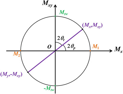
FIGURE 2. Construction of Mohr’s circle for the thermal moment resultant from ply angle misalignments. In the initial ply reference orientation, there are the bending moments Mx and My and the twisting moment concurrently; in an inclined surface with rotation angle θt (or θp) in fact and 2θt (or 2θp) in figure, there is only the maximum twisting moment Mtw (or the principal moment M1 and M2).
Let’s set m'2 = 0 in Eq. 8, then the rotation angle θt in Figure 2 could be given as follows:
Similarly, let’s set m'1 = 0 in Eq. 8, and the rotation angle θp (as shown in Figure 2) is as follows:
The angle θp is the principal moment direction. It is well known that two values at the circumference match with Eq. 9, 10, respectively. As customary θp1 and θp2 indicate directions of maximum and minimum principal moments when the corresponding m2 is greater and less than zero, θt1 and θt2 represented orientations of maximum positive and negative twisting moments. Directions after rotating twice of the preceding two rotation angles are parallel to each other, or the difference between two rotation angles is 45°.
In addition, m1 and m2 are independent of the temperature change. The rotation angles, θt and θp, are not correlated with the temperature change and are just dependent on stacking sequences and ply angle misalignments. In other words, for symmetric and quasi-isotropic laminates, the principal moment direction is a particular property of the laminate with regard to ply misalignments. It remains unchanged during curing inside the autoclave or under temperature cycles in the space environment.
If only one-ply angle misalignment occurs, Eq. 9 is simplified to the following:
According to the preceding statement, the abovementioned formula indicates that one direction of the maximum twisting moments is parallel to the kth ply orientation and the other is perpendicular to that, and the principal moment directions are always orientated at ± 45° from that, namely, as shown below:
Furthermore, for multiple ply angle misalignments θt can be gained by Eq. 9, which also indicates the direction of maximum or minimum twisting moment. To better distinguish them from θt, we defined the generalized ply angle, denoted as θG, where the ply angle misalignment occurs nominally, the twisting moment locates at the peak or valley, and is 45° apart from principal moment directions.
3 Simulation Analysis
3.1 Material and Model
The model is shown in Figure 3, a concave mirror, 2.4 mm thick, with a diameter of 500 mm intercepted from a spherical surface of radius 1,600 mm. There are 9,000 elements, and the angle of each element in the circular direction is approximately 1°. It is made of the carbon fiber composite M40/602, and its properties are detailed in Table 1. In total, six freedoms of its center are fixed, and the mirror was only subjected to the thermal load, ΔT = −100°C, uniformly cooling from the curing temperature (125°C) to the room temperature (25°C). In addition, the ply reference direction was along the x-axis, y-axis was 90° direction, and normal direction was along the z-axis. This definition ensured that the angles in the coordinate were consistent with the ply angles.
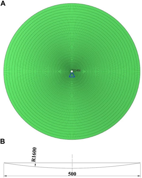
FIGURE 3. Model of the space mirror. (A) Finite element with the fixed center point and (B) Front view.

TABLE 1. Material properties of the unidirectional carbon fiber composite M40J/602.
3.2 Stacking Sequences
A total of six quasi-isotropic and symmetric stacking sequences (shown in Table 2) (Liu et al., 2019) were used to simulate out-of-plane deformations with ply angle misalignments. The stacking sequence with ply angle misalignments is regarded as part of the material property in Abaqus. For the symmetric laminate [B] = 0, the in-plane and out-of-plane deformations were independent of each other. Concerning the quasi-isotropic laminate, the equivalent coefficients of thermal expansion were identical at the circumference. Therefore, the space mirror should be expanded slightly and uniformly in-plane during its curing process and the temperature cycle in the space environment, and it was usually neglected in consideration of the out-of-plane deformation.

TABLE 2. Typical stacking sequences.
The first three stacking sequences all had 24 layers with the ply thickness of 0.1 mm but different ply angles, namely, 3, 6, and 12 angles in turn, and the last three stacking sequences, which had 32 layers, were 0.075 mm in thickness, and the number of the ply orientations were 4, 8, and 16, respectively.
4 Results and Discussion
4.1 Fixed Ply Angle Misalignment
The fixed ply angle misalignment, unit angle 1°, is allowed to occur on the first layer, and then, the mirrors’ response to the thermal load is calculated. Figure 4 shows displacement contours in the z-axis direction. Compared with Table 2, each displacement contour takes on a saddle shape, and there are two peaks and two valleys separated from each other. According to the differential geometry principle, two peaks corresponded to the maximum curvature, κ1, and two valleys corresponded to the minimum curvature, κ2 (as shown in Figure 5). Meanwhile, there exists another typical curvature, the maximum twisting curvature, κtw, was located on the angular bisector of the maximum and minimum curvature.
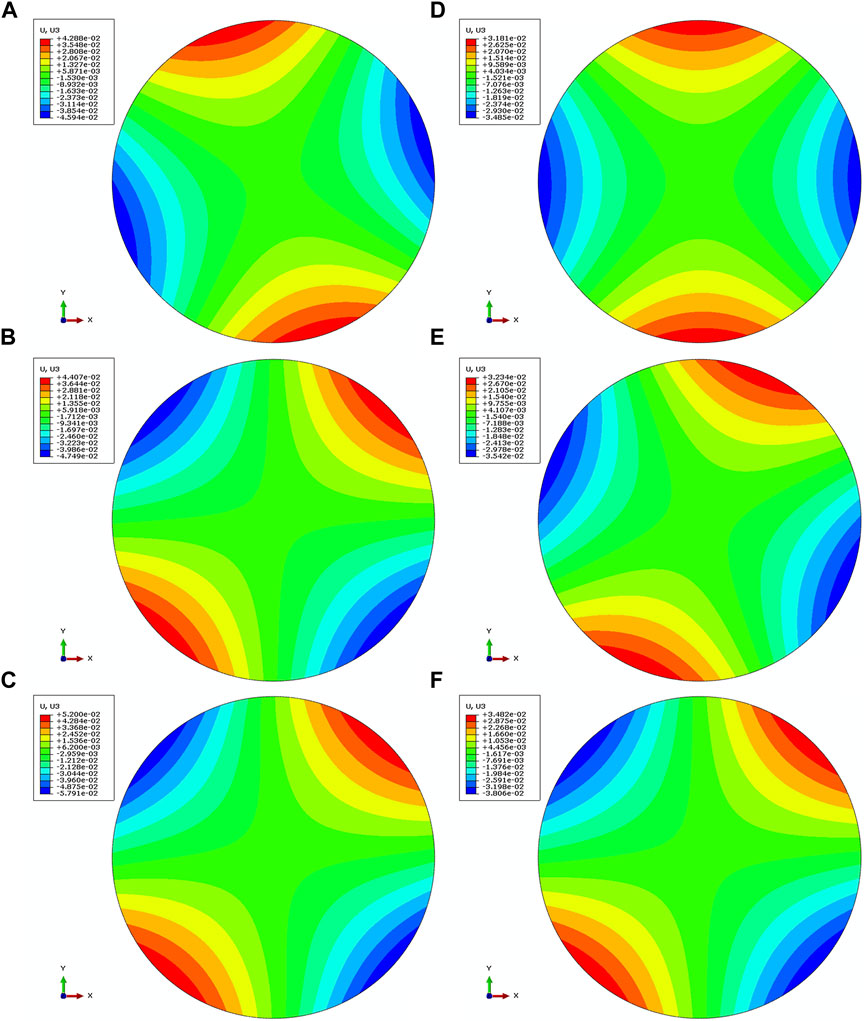
FIGURE 4. Out-of-plane deformation for six stacking sequences with unit ply angle misalignment in the first layer. (A) Stacking No. 1; (B) Stacking No. 2; (C) Stacking No. 3; (D) Stacking No. 4; (E) Stacking No. 5; (F) Stacking No. 6.
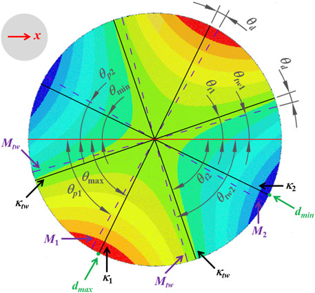
FIGURE 5. Diagram of principal moments and curvatures, the maximum twisting moment and curvature, and the deflection angle. dmax and dmin denote the maximum and minimum displacements, respectively. The black solid lines are the principal curvatures, κ1 and κ2, the maximum twisting curvature, κtw, and the corresponding directions are the maximum and minimum principal curvature directions, θmax and θmin, and the direction of the maximum twisting curvatures, θtw1 and θtw2; the purple dotted lines are the principal moments, M1 and M2, the maximum twisting moment, Mtw, and the corresponding directions are the maximum and minimum principal moment directions, θp1 and θp2, and the directions of the maximum twisting curvature, θt1 and θt2.
Extract displacement reports and the associated angles could be achieved through coordinates of nodes, and the effect of in-plane displacements was ignored. Data are listed in Table 3. Directions of κ1, κ2, and κtw are indicated as θmax, θmin, and θtw, respectively. In addition, the maximum and minimum displacements are expressed as dmax and dmin (as shown in Figure 5).

TABLE 3. Results of the generalized ply angles and angles of minimum and maximum displacements with unit ply angle misalignment in the first layer.
In Table 3, the 2nd column, θG, has been achieved by Eq. 9, and the 7th column, θtw, is the average of the 4th and 6th columns. The last column shows differences between the direction of the maximum twisting curvature and the generalized ply angle, which are hardly equal to 0° but only closer to 0°. The angle of each grid is approximately 1°, and the calculation accuracy is about 0.5°. All six results still exceed the angle range of 0° even considering the accuracy of the grid. Therefore, the direction of the maximum twisting curvature is different from that of the generalized ply angles, and this difference is named the deflection angle θd.
Furthermore, the fixed ply angle misalignment, unit angle 1°, is allowed to occur on any ply and only one ply at a time, instead of just the first ply, and deformations and analysis deflection angles are calculated. The min and max deflection angles for six stacking sequences are shown in Table 4. It indicates that the deflection angle range varies with each stacking sequence. All deflection angles for Stacking No. 2 are detailed in Table 5. When the generalized ply angles are 0°, 30°, and −30°, the corresponding deflection angles are just equal to 1°, −1°, and 2°, respectively. For the other stacking sequences, we can also obtain similar results. Meanwhile, the deflection angles of Stacking No. 4 are always 1° (as shown in Table 4). Therefore, the deflection angle also changes with the generalized ply angle within each laminate. In other words, deflection angles remain constant for the same generalized ply angle.
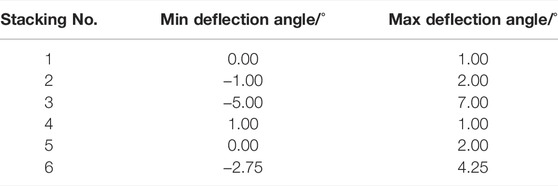
TABLE 4. Deflection angle ranges of six stacking sequences with unit ply angle misalignment in each layer at one time.

TABLE 5. Deflection angles of Stacking No. 2 with unit ply angle misalignment in each layer at one time.
If the influence of ply angle misalignments on the stiffness matrix is ignored, for the symmetric laminate, the curvature and the moment followed by {κ} = [D]−1{MT}. In consideration of the same kth ply with the fixed ply angle misalignment, according to Eq. 7, the magnitudes of the resultant thermal moment from Stacking No. 1 to Stacking No. 3 are identical to each other, as well as that from Stacking No. 4 to No. 6, and they locate at each generalized ply angle. Then, differences between out-of-plane deformations, including principal curvature directions and deflection angles, could be attributed to the bending stiffness matrix. So the deflection angle is closely related to the bending stiffness matrix.
Furthermore, for the uniform bending stiffness or the isotropic material, the principal curvature directions are always consistent with the principal moment directions. Consecutively, when the deflection angle exists, the bending stiffness at the circumference changes gradually. In other words, the deflection angle reflects the uniformity of bending stiffness. The smaller the amplitude of the deflection angle, the better is the uniformity of bending stiffness.
4.2 Random Ply Angle Misalignments
Based on stacking sequences in Table 2, a series of random numbers were imposed on them. The random numbers were generated from MATLAB and obeyed the normal distribution. The probability density function was defined as follows:
where μ was the mean value, and σ was the standard misalignment. In this study, the mean value was 0, and σ was set to 1.5.
The combined stacking sequences were sent to Abaqus by applications of Python script and were acted on the space mirror in turn, namely, the Monte Carlo method (Liu et al., 2019). The number of cycles was 10,000. After calculation, responses were extracted, including coordinates and displacements of nodes; then, the data were analyzed by the aforementioned statement.
Diagrams of the deflection angle versus the generalized ply angle are shown in Figure 6. The deflection angle changes with the generalized ply angle approximately as a trigonometric function within each laminate.
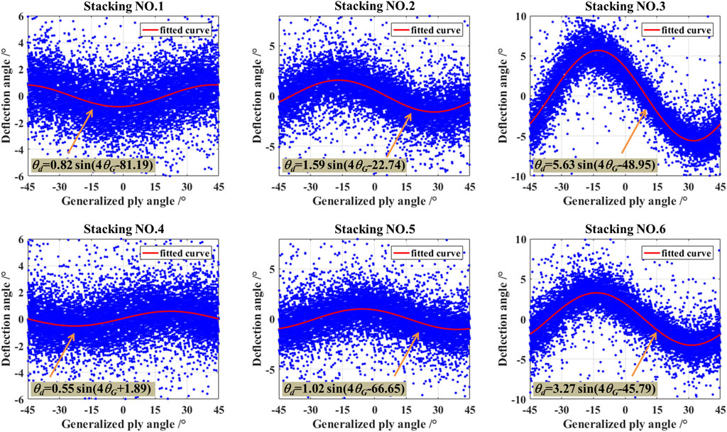
FIGURE 6. Point diagrams and fitting curves (including fitting functions) of the deflection angle versus the generalized ply angle for Stacking Nos. 1–6.
The fitting curve and function of the deflection angle have been drawn in the diagram. The amplitudes of the fitting functions are different from each other. Amplitudes for Stacking Nos. 1–6 are 0.82, 1.59, 5.63, 0.55, 1.02, and 3.27, respectively. It indicates that Stacking Nos. 1 and 4 are the smallest, Stacking Nos. 3 and 6 are the biggest, and Stacking Nos. 2 and 5 are in the middle.
Therefore, Stacking Nos. 1 and 4 have faster tendencies to the uniform bending stiffness than others. The diagram of deflection angles, especially amplitudes, could be used to compare the consistency of bending stiffness.
Compared to the method of the regularization stiffness coefficient and coefficients of bending/twisting, the deflection angle is a comprehensive value to indicate the relationship between the twisting stiffness and the bending stiffness. It provides an objective way to compare the uniformity of bending stiffness to obtain a laminate with the more uniform bending stiffness.
5 Conclusion
By applications of theoretical derivation, simulation, and comparison, it could be concluded that:
1) the principal moment direction is 45° to the generalized ply angle, resulting from the ply angle misalignments;
2) the deflection angle, derived from the angle misalignment, essentially has nothing to do with the angle misalignment and is an inherent property of the laminate;
3) the deflection angle varies from the stacking sequence and is dependent on the generalized ply angle. In addition, it is approximately made of a trigonometric curve and the amplitude of the fitting trigonometric function is a parameter to be compared;
4) the smaller the deflection angle, the better is the uniformity of bending stiffness. Thus, it is an efficient approach to achieve a stacking sequence with more uniformity of bending stiffness by comparing the deflection angle.
Therefore, for a symmetric and quasi-isotropic laminate, we could predict the principal moment and curvature directions resulting from ply angle misalignments and obtain their difference and the deflection angle. It is beneficial to optimize stacking sequences and precisely control the accuracy of the mirror by stacking sequences.
Data Availability Statement
The original contributions presented in the study are included in the article/Supplementary Material, further inquiries can be directed to the corresponding authors.
Author Contributions
LL and FS suggested this study, analyzed data, and wrote the manuscript. QL performed the research, analyzed data, and wrote the manuscript. All authors discussed the results and commented on the manuscript.
Funding
This work was supported by the National Natural Science Foundation of China (Grant Nos. 11972041 and 11902327) and the Youth Innovation Promotion Association CAS.
Conflict of Interest
The authors declare that the research was conducted in the absence of any commercial or financial relationships that could be construed as a potential conflict of interest.
Publisher’s Note
All claims expressed in this article are solely those of the authors and do not necessarily represent those of their affiliated organizations, or those of the publisher, the editors, and the reviewers. Any product that may be evaluated in this article, or claim that may be made by its manufacturer, is not guaranteed or endorsed by the publisher.
References
Arao, Y., Koyanagi, J., Utsunomiya, S., and Kawada, H. (2011). Effect of Ply Angle Misalignment on Out-Of-Plane Deformation of Symmetrical Cross-Ply CFRP Laminates: Accuracy of the Ply Angle Alignment. Compos. Structures 93 (4), 1225–1230. doi:10.1016/j.compstruct.2010.10.019
Bowers, C. W., Bowers, C. W., Content, D. A., Marzouk, M., and Romeo, R. C. (2000). Advances in Very Lightweight Composite Mirror Technology. Opt. Eng. 39 (9), 2320–2329. doi:10.1117/1.1288125
Bruyneel, M., Beghin, C., Craveur, G., Grihon, S., and Sosonkina, M. (2012). Stacking Sequence Optimization for Constant Stiffness Laminates Based on a Continuous Optimization Approach. Struct. Multidisc Optim 46 (6), 783–794. doi:10.1007/s00158-012-0806-4
Chen, Y., Ye, L., and Fu, K. (2021). Progressive Failure of CFRP Tubes Reinforced with Composite sandwich Panels: Numerical Analysis and Energy Absorption. Compos. Structures 263, 113674. doi:10.1016/j.compstruct.2021.113674
Cheng, L., Gong, P., Wang, Q., Zou, M., Zhang, Y., and Liu, Z. (2021). Effects of Ply Thickness Deviation and Ply Angle Misalignment on the Surface Accuracy of CFRP Laminates. Compos. Structures 270, 114073. doi:10.1016/j.compstruct.2021.114073
Fukunaga, H. (1990). On Isotropic Laminate Configurations. J. Compos. Mater. 24 (5), 519–535. doi:10.1177/002199839002400504
Fukunaga, H., and Sekine, H. (1992). Stiffness Design Method of Symmetric Laminates Using Lamination Parameters. AIAA J. 30 (11), 2791–2793. doi:10.2514/3.11304
Gere, J. M., and Goodno, B. J. (2012). Mechanics of Materials. 8th edition edn. Stamford: Cengage Learning.
Hyer, M. W. (1981). Some Observations on the Cured Shape of Thin Unsymmetric Laminates. J. Compos. Mater. 15, 175–194. doi:10.1177/002199838101500207
Kim, K.-P., and Hale, R. D. (2010). Composite Mirror Surface Deformation Due to Lay-Up Sequences within Quasi-Isotropic Laminates. Opt. Eng. 49 (6), 063002–063010. doi:10.1117/1.3456694
Liu, Q., Cai, Y., Liu, X., Yang, Z., Jiang, S., and Leng, S. (2019). Influence of the Ply Angle Deviation on the Out-Of-Plane Deformation of the Composite Space Mirror. Appl. Compos. Mater. 26 (3), 897–911. doi:10.1007/s10443-018-9756-3
Ma, G., Kang, R., Dong, Z., Yin, S., Bao, Y., and Guo, D. (2020). Hole Quality in Longitudinal-Torsional Coupled Ultrasonic Vibration Assisted Drilling of Carbon Fiber Reinforced Plastics. Front. Mech. Eng. 15 (4), 538–546. doi:10.1007/s11465-020-0598-y
Różyło, P., and Dębski, H. (2022). The Influence of Composite Lay-Up on the Stability of a Structure with Closed Section. Adv. Sci. Technol. Res. J. 16 (1), 260–265. doi:10.12913/22998624/145156
Song, C., and Jin, X. (2021). Fracture Angle Prediction for Matrix Failure of Carbon-Fiber-Reinforced Polymer Using Energy Method. Composites Sci. Tech. 211, 108869. doi:10.1016/j.compscitech.2021.108869
Steeves, J., and Pellegrino, S. (2017). Post-cure Shape Errors of Ultra-thin Symmetric CFRP Laminates: Effect of Ply-Level Imperfections. Compos. Structures 164, 237–247. doi:10.1016/j.compstruct.2016.12.075
Tanaka, S., Ikeda, T., and Senba, A. (2016). Sensitivity Analysis of thermal Deformation of CFRP Laminate Reflector Due to Fiber Orientation Error. J. Mech. Sci. Technol. 30 (10), 4423–4426. doi:10.1007/s12206-016-0905-z
Thompson, S. J., Bichon, S., and Grant, R. J. (2014). Influence of Ply Misalignment on Form Error in the Manufacturing of CFRP Mirrors. Opt. Mater. Express 4 (1), 79–91. doi:10.1364/ome.4.000079
Vannucci, P., and Verchery, G. (2002). A New Method for Generating Fully Isotropic Laminates. Compos. Structures 58 (1), 75–82. doi:10.1016/S0263-8223(02)00038-7
Verchery, G. (2011). Design Rules for the Laminate Stiffness. Mech. Compos. Mater. 47 (1), 47–58. doi:10.1007/s11029-011-9186-x
Wei, L., Zhang, L., and Gong, X. (2017). Design and Optimization of the CFRP Mirror Components. Photonic. Sens. 7 (3), 270–277. doi:10.1007/s13320-017-0388-2
Wilhelmsson, D., Rikemanson, D., Bru, T., and Asp, L. E. (2020). Compressive Strength Assessment of a CFRP Aero-Engine Component - an Approach Based on Measured Fibre Misalignment Angles. Compos. Structures 233, 111632. doi:10.1016/j.compstruct.2019.111632
Wu, K. M., and Avery, B. L. (1992). Fully Isotropic Laminates and Quasi-Homogeneous Anisotropic Laminates*. J. Compos. Mater. 26 (14), 2107–2117. doi:10.1177/002199839202601406
Xie, F., Lu, Z., Yang, Z., Hu, W., and Yuan, Z. (2016). Mechanical Behaviors and Molecular Deformation Mechanisms of Polymers under High Speed Shock Compression: a Molecular Dynamics Simulation Study. Polymer 98, 294–304. doi:10.1016/j.polymer.2016.06.047
Yang, Z., Tang, Z., Xie, Y., Shi, H., Zhang, B., and Guo, H. (2018). Effect of Lamina Thickness of Prepreg on the Surface Accuracy of Carbon Fiber Composite Space Mirrors. Appl. Compos. Mater. 25 (1), 105–112. doi:10.1007/s10443-017-9604-x
Yang, Z., Liu, Q., Zhang, B., Xu, L., Tang, Z., and Xie, Y. (2019). Influence of Layup Sequence on the Surface Accuracy of Carbon Fiber Composite Space Mirrors. Appl. Compos. Mater. 26 (1), 219–238. doi:10.1007/s10443-018-9690-4
Yi, X., Du, S., and Zhang, L. (2018). Fundamentals of Composite Materials, Vol. 1. Beijing: Chemical Industry Press. doi:10.1007/978-981-10-5696-3
Keywords: carbon fiber–reinforced polymer, bending stiffness, ply angle misalignment, principal direction, generalized ply angle, deflection angle
Citation: Liu Q, Shao Y, Li L, Cai Y and Song F (2022) Uniformity Prediction of Bending Stiffness of Composite Space Mirrors With Ply Angle Misalignments by Deflection Angle. Front. Mech. Eng 8:888350. doi: 10.3389/fmech.2022.888350
Received: 02 March 2022; Accepted: 28 March 2022;
Published: 29 April 2022.
Edited by:
Zhaohe Dai, University of Oxford, United KingdomCopyright © 2022 Liu, Shao, Li, Cai and Song. This is an open-access article distributed under the terms of the Creative Commons Attribution License (CC BY). The use, distribution or reproduction in other forums is permitted, provided the original author(s) and the copyright owner(s) are credited and that the original publication in this journal is cited, in accordance with accepted academic practice. No use, distribution or reproduction is permitted which does not comply with these terms.
*Correspondence: Long Li, bGlsb25nQGxubS5pbWVjaC5hYy5jbg==; Fan Song, c29uZ2ZAbG5tLmltZWNoLmFjLmNu