 Rafael Menaca1*
 Mickael Silva2
 Kalim Uddeen1
 Fahad Almatrafi1
 Qinglong Tang3James W. G. Turner1Hong G. Im1
- 1Clean Energy Research Platform (CERP), King Abdullah University of Science and Technology, Thuwal, Saudi Arabia
- 2Aramco Americas: Aramco Research Center, Detroit, MI, United States
- 3State Key Laboratory of Engines, Tianjin University, Tianjin, China
Ammonia (NH3) stands out as a promising candidate for fueling internal combustion engines, owing to its high hydrogen content and well-established production and transport infrastructure. Nevertheless, its inherently low flame speed and reactivity pose a significant challenge to achieving rapid and complete combustion. One potential solution is the use of multi-spark ignition, wherein multiple spark plugs distribute ignition sites throughout the combustion chamber, thereby accelerating flame propagation across the entire charge. In this study, a three-dimensional 3D-CFD model of multi-spark, spark-ignited NH3 internal combustion engine is developed and validated using optical engine experiments. The optical data provide critical insights into early flame kernel development, guiding refinements to two combustion submodels (SAGE and G-equation). Results underscore the importance of sufficiently refined mesh resolution—particularly near the spark plugs—and the incorporation of detailed spark plug geometries to accurately capture the early stages of ignition in low-reactivity fuels such as NH3. Overall, the close qualitative agreement between measured flame luminosity and simulated flame evolution demonstrates the robustness of the proposed CFD framework.
1 Introduction
Meeting world energy demands relies primarily on the utilization of hydrocarbon fuels. The transport sector represents about 20% of total energy consumption, with road mobility accounting for 72% of this fraction Bilgen (2014). In the U.S., the transportation sector is the leading emitter of greenhouse gases EPA (2024). To achieve future international environmental goals, a mix of technologies has been proposed in recent years to reduce the overall fleet emissions. This can be accomplished either by enhancing engine efficiency or by utilizing alternative fuels with minimal carbon emissions. Ammonia (
In the spark-ignited (SI) application, due to the high-octane number of
Additionally, different techniques for
An alternative approach to increasing the burning rate in
Silva et al. (2023) conducted a computational fluid dynamics (CFD) assessment to determine the optimal engine operating conditions for achieving maximum efficiency with pure
Building on the prior modeling experience, this study attempts to develop an improved computational fluid dynamics (CFD) simulation practices as a means to guide the development of successful
2 Optical experiments
The experiment was performed on a single-cylinder four-stroke optical research compression-ignition engine (AVL-5402), which was converted into SI engine conditions. An AVL PUMA automation system (V2012) was used to control and monitor the engine conditions. The combustion was initiated by four side spark plugs (ER8EH, NGK), which were equally spaced and installed around the circumference of a specialized metal liner labeled from SP 1 to 4, and another spark plug (C) mounted at the top of the cylinder head. Additionally, an AVL-GU22CK pressure transducer (T) was installed on the top of the cylinder head to record the in-cylinder pressure. A flat-quartz, extended Bowditch piston (Suprasil 2 grade B) was employed, as seen in Figure 1. To capture the flame images from below, a
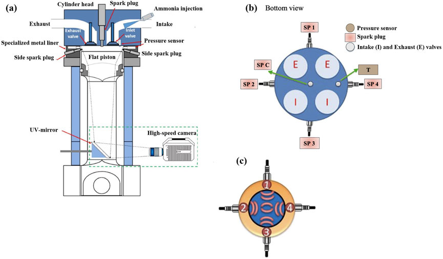
Figure 1. a) Schematic of the setup, (b) bottom view of the combustion chamber arrangement, highlighting the multiple spark locations, and (c) flame front development patterns Uddeen et al. (2023a); Uddeen et al. (2023b); Uddeen et al. (2023c).
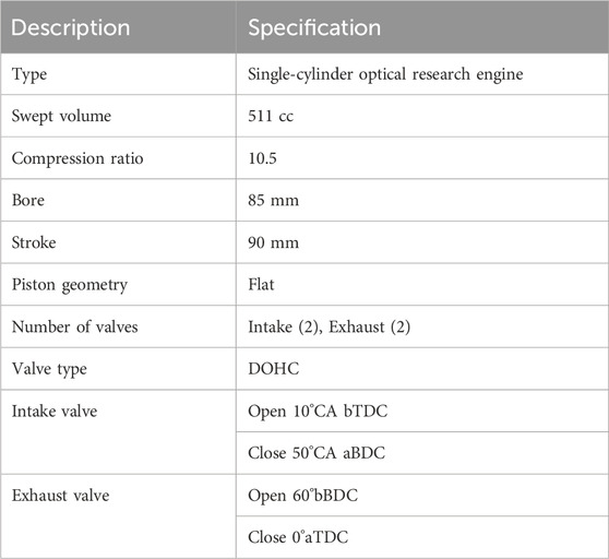
Table 1. Engine specifications.
3 Computational model
3.1 Numerical configuration
The AVL optical engine was modeled and the numerical simulations were executed by the density-based finite volume CFD solver
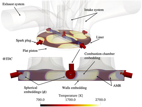
Figure 2. Computational domain and mesh characteristics.
Boundary conditions were imposed based on the experimental measurements Uddeen et al. (2023a); Uddeen et al. (2023b); Uddeen et al. (2023c). The mixture composition was stoichiometric and assumed as a perfectly mixed inflow boundary condition. Constant Dirichlet pressure inlet and outlet boundary conditions were set, simplifying the exchange gases process, yet capturing the correct delivered mass per cycle. Piston, liner and head walls temperatures were kept at 450 K, while the intake and exhaust systems temperatures were maintained at 333 K and 500 K, respectively. To model ignition, a spherical energy source was placed at each spark plug electrode gap. The ST was set to
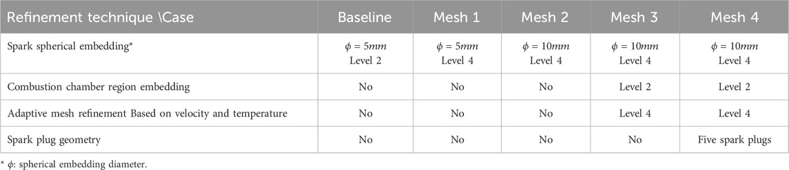
Table 2. Mesh features in the mesh sensitivity analysis.
3.2 Validation stage and simulation strategy
The first step in the calibration of the engine model was related to the proper representation of the compression and expansion of the in-cylinder gases. Optical engines experience a significant level of leakage due to hardware modifications and the setup configuration. Therefore, to assure accurate reproduction of the pressure history, a proper crevice model is crucial. Following the studies by Irimescu et al. (2013); Irimescu et al. (2018); De Renzis et al. (2021), 7.5% of the total inducted mass per cycle was allowed to leak to the crankcase. The model was further calibrated while maintaining the squish height as in the engine, leading to a geometrical compression ratio of 12. The results are presented in Figure 3, revealing close agreement with the experimental data, particularly during the expansion stroke. This level of accuracy is especially noteworthy given the optical configuration of the engine under investigation.
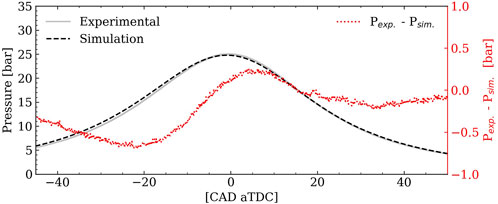
Figure 3. Motoring pressure evolution comparison between experiments and numerical results.
Subsequently, combustion cases are calibrated, starting from mesh sensitivity; different mesh strategies were tested and as summarized in Table 2. The baseline case setup is established based on literature Yang et al. (2023), whereas the additional mesh features were considered to improve the description of the initial kernel growth with the refinement of the mesh in the spark plug region. Additionally, a cylindrical embedding of the combustion chamber was explored in meshes three and four to observe the keys aspects of the main chamber turbulence dissipation, along with the AMR to refine the flame zones. Finally, the geometry of all the spark plugs was introduced in Mesh four and its effects on the combustion behavior will be explained in detail below.
4 Assessment of numerical parameters
4.1 Mesh sensitivity analysis
Figure 4a presents the pressure and apparent heat release rate (AHRR) evolutions for the different evaluated cases, with 100 experimental combustion cycles shown in gray for reference. At first glance, the Baseline, Mesh 1, and Mesh two simulations underpredict the pressure rise despite accurately capturing the ignition delay, indicating a slower heat release rate compared to the experiments. This discrepancy can be attributed to the coarse mesh resolution in the spark plug region and insufficient refinement during the early stages of combustion. In particular, coarse meshes promote a rapid energy dissipation, which reduces the reactivity of the cell-based ignition in the SAGE combustion model.
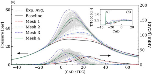
Figure 4. (a) Pressure evolution and AHRR, and (b) volume-averaged temperature in the SPC region during the energy deposition period, for the various cases evaluated in the mesh sensitivity analysis.
Additional evidence appears in Figure 4b, which shows how the temperature in the SPC vicinity rapidly decays for the coarse meshes. In the Baseline mesh, the peak temperature is even lower due to this rapid energy dissipation. A second temperature peak occurs once combustion initiates; notably, this peak appears earlier for Mesh three and takes longer in the coarser meshes, indicating a slower heat release process.
In contrast, Mesh three overpredicts the heat release rate and the peak pressure reaches higher values compared to experiments. Although the mesh in the spark plug surroundings is refined, as well as the combustion chamber, the early flame development is shorter and a rapid rise of the in-cylinder pressure is substantial. To understand how the local flow field and early flame development are affected by the presence of spark plugs geometry (J-gap type), their geometrical details are included in Mesh 4. Remarkably, the prediction is much improved, suggesting the importance of capturing the near-spark flow field during the early combustion development. To obtain additional insights about the importance of the detailed geometry, additional test simulations were done with the spark plugs rotated (results not shown in the document), but marginal changes were observed in the numerical results. It is thus concluded that the most important aspect is the local flow field near the wall.
These findings suggest that typical engine CFD meshing practices for hydrocarbon fuels may not be fully applicable to
4.2 Effect of heat transfer model
Different heat transfer models may be selected for the law-of-the-wall temperature boundary condition treatments available in CONVERGE, such as GruMo-UniMORE by Berni et al. (2017), Amsden, 1997, and Han and Reitz (1997). A proper heat transfer description is necessary to correctly describe the flow physics in the combustion chamber, especially at the end of the compression stroke and during combustion period when the walls are experiencing higher heat transfer rates. As the viscous sublayer is not resolved, it is necessary to model the temperature profile near the wall. In addition to the heat transfer equation, the transition of the logarithmic layer,
Figure 5 shows that the implementation of the three different models lead to a similar behavior in the pressure and AHRR evolution, with the O’Rourke model predicting a slightly higher peak pressure and AHRR. This suggests that the heat losses are minimal when using this model. On the other hand, the AHRR peak in GruMO-UniMORE and Han and Reitz is similar, with the latter predicting a longer combustion duration. In addition, the pressure peak is lower for the Han and Reitz results, indicating higher heat transfer losses, observed as well in the lower pressure captured towards the end of the compression stroke. Considering the small variations, for this specific engine configuration running with
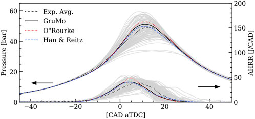
Figure 5. Pressure and AHRR traces for the different evaluated heat transfer models.
4.3 Effect of spark timing
The reference ST was set at −30 CAD aTDC. Given the lack of data in optical
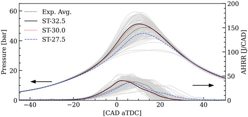
Figure 6. Pressure and AHRR traces for the different evaluated STs.
5 Combustion modeling and flame behavior
5.1 Natural flame luminosity
To further demonstrate the fidelity of the model, the instantaneous flame development and topology is analyzed in Figure 7. In the first row (a) optical experiments are presented, whereas the second row (b) shows the computational volumetric rendering of the temperature field. Upon initial inspection, the CFD results demonstrate a qualitatively accurate prediction of flame development from the five different spark locations. However, the numerically predicted flame growth appears slightly faster than in the experiments, which may relate to the higher AHRR observed in Mesh 4 (see Figure 4). Furthermore, it should be noted that the experimental optical setup does not capture the entire outer region of the combustion chamber, and the single-shot image from the experiment may differ from the ensemble-averaged RANS solution. In the initial stages of combustion at −10 CAD, the flame surface areas are small, and then grow towards top dead center (TDC), increasing the pressure and temperature of the combustion chamber. At 10 CAD, the different flame fronts have merged towards the late combustion, consuming nearly the entire unburned premixed charge. As reported in previous studies by Huang and Liu (2024), the multi-spark methodology speeds up the overall charge consumption due to the simultaneous creation of multiple flame fronts. One important observation is the flame resultant from the central spark (SPC) growing with a faster rate. Furthermore, it is observed that the topology for the different flames differ among them, as further discussed later.
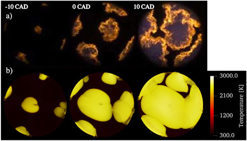
Figure 7. Flame development viewed from the bottom captured by (a) natural flame luminosity experiments and (b) numerical results with Mesh 4 model. Volumetric post-processing for the temperature field.
5.2 Flame dynamics
The volumetric-averaged turbulent kinetic energy (TKE) at each spark location is presented in Figure 8. There are two important peaks during the cycle. The first one corresponds to the intake valve opening event, promoting the increase in the TKE as a consequence of the entering turbulent inflow mixture charging the main chamber. The second peak occurs at the ST, where the sudden rise in the pressure and the expansion of the flames disturb the local flow field. It is seen that TKE is higher at SPC before the start of ignition, which promotes the central flame to grow faster. Additionally, higher fluctuations are observed in this region. There is irregular behaviors in the different regions during the intake stroke. However, the level of turbulence decays once the intake valves are closed. Towards the compression stroke, the fluctuations in the flow field remain at similar low values.
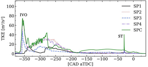
Figure 8. Volume-averaged TKE evolution at the five different spark plug regions.
It is evident that each flame front behaves distinctly as a consequence the different local flow field conditions at ST and afterwards; this implies the need for appropriate mesh selections at different regions to capture the detailed turbulent flow characteristics in addition to the spark geometry. Furthermore, due to the turbulent flows and the swirl-type engine, the in-cylinder fluid dynamics varies spatially, translating in a complex flame-flame interaction. The present results show significant differences from those obtained by Huang and Liu (2024), where a simplified initial setup resulted in multiple flame fronts propagating in comparable shapes and sizes. The present study suggests that capturing local variations in the flow and flame behavior may lead to a significant difference in the prediction of the overall engine combustion characteristics.
More details of the flow field are shown in Figure 9 along with the TKE map. The higher TKE found in the center of the combustion chamber is found to be caused by the swirl motion. The rotational motion promotes an increase in the pressure close to the walls, where the velocity is zero due to the non-slip condition; the boundary layers of the piston and head induce the flow to move inwards to the center of the combustion chamber. As a consequence of the different streams collapsing, velocity fluctuations are concentrated in that region. The iso-surface for T = 1700 K represents the flames in Figure 9. Due to the growth of the multiple flames and the heat release during combustion, the gas expansions at different locations affects the flow patterns, where multiple locus of flow stagnation are observed as a result of the flames propagating onto the fresh charge.
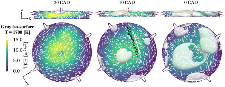
Figure 9. Vector field, TKE profile and iso-surface for T = 1700 K, at different timings in the combustion chamber. Top: xz-plane view; Bottom: rotated xy-plane at z = −3 mm.
5.3 Turbulence-chemistry interaction
Turbulence varies significantly both spatially and temporally throughout the cycle. These variations have a crucial influence on flame dynamics and need to be properly captured in the model. The SAGE combustion model treats each computational cell as a homogeneous (well-stirred) reactor. Accordingly, within the RANS framework, turbulence-chemistry interactions (TCI) are effectively neglected, as local reaction rates are computed solely from the mean flow field and temperature without accounting for sub-grid fluctuations Mohan and Haworth (2015). To properly account for TCI in the context of flame propagation, the G-Equation combustion model is being employed, where a transport equation for the scalar field variable
Equation 1 comprises several variables and constants, including the turbulent flame speed represented by
where the turbulent Damköhler number is defined as
Unlike the SAGE model, which initiates combustion via an energy source that mimics the arc discharge to trigger reactions, standard ignition practice for the G-equation model is to initialize the corresponding
Both sources are spherical with a radius of 0.5 mm, activated simultaneously at the ST. Figure 10 shows the pressure and AHRR traces obtained using the G-equation combustion model, with experimental pressure traces for comparison. The combustion process is accurately captured, with small deviations observed in the numerical results, particularly at the early stages of combustion. Consequently, the model effectively characterizes the flame-flow interaction, providing a solid foundation for evaluating key aspects of the turbulence-chemistry interaction.
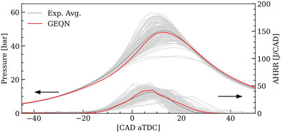
Figure 10. Pressure evolution for the G-equation model.
Figure 11 shows the visual flame development in the combustion chamber based on the iso-surface for the flame
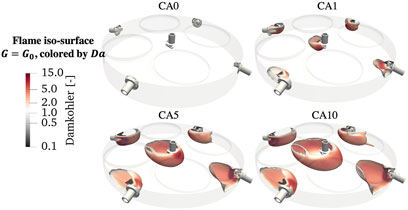
Figure 11. Iso-surface representing the flame
Huang and Liu (2024) suggested that the inclusion of multiple sparks does not enhance turbulence levels in the chamber; instead, the advantage of this approach lies in the ignition multi-locus adjoined propagation. This behavior is akin to advanced combustion systems like the pre-chamber, where multiple ignition locations are achieved. Unlike the pre-chamber method, however, the multi-spark approach does not enhance turbulence and mixing.
6 Conclusion
In this study, a three-dimensional CFD model for SI, multi-spark NH3 internal combustion engine was developed and validated using optical engine experiments. Because NH3 exhibits lower reactivity compared to carbon-based fuels, it necessitates more stringent mesh resolution and spark-region modeling. Incorporating detailed spark plug geometries was found to be critical for accurately resolving early flame kernel development by improving the local flow field and temperature distribution at the onset of ignition.
When compared against natural flame luminosity measurements, the model demonstrated a high degree of qualitative agreement, indicating that key physical processes—such as ignition, flame propagation, and local turbulent mixing—are effectively reproduced. An assessment of turbulence–chemistry interactions further revealed that NH3 combustion can shift from a chemistry-governed to a flow-governed regime, underscoring the pivotal role of turbulent kinetic energy in accelerating flame growth. Additionally, for the G-equation model (a flame-based approach), a small energy boost in the spark plug region following flame initialization was required to enhance initial kernel growth, reflecting
Building on this work, future investigations will leverage CFD simulations to explore advanced combustion strategies, examine varied operating parameters, and optimize engine designs.
Data availability statement
The raw data supporting the conclusions of this article will be made available by the authors, without undue reservation.
Author contributions
RM: Conceptualization, Data curation, Formal Analysis, Investigation, Methodology, Software, Visualization, Writing–original draft, Writing–review and editing. MS: Conceptualization, Formal Analysis, Investigation, Methodology, Software, Supervision, Writing–review and editing. KU: Conceptualization, Data curation, Writing–original draft, Writing–review and editing. FA: Conceptualization, Writing–review and editing. QT: Writing–review and editing. JT: Funding acquisition, Project administration, Resources, Writing–review and editing. HI: Conceptualization, Funding acquisition, Project administration, Resources, Supervision, Writing–review and editing, Formal Analysis.
Funding
The author(s) declare that financial support was received for the research, authorship, and/or publication of this article. This work was funded by the King Abdullah University of Science and Technology in Saudi Arabia.
Acknowledgments
The simulations were conducted using the high-performance computation resources of Shaheen supercomputer at KAUST Supercomputing Laboratory. The authors thank Convergent Science Inc. for providing the CONVERGE license. GPT-4 from OpenAI was used to check for English grammar and to improve writing coherence.
Conflict of interest
The authors declare that the research was conducted in the absence of any commercial or financial relationships that could be construed as a potential conflict of interest.
Publisher’s note
All claims expressed in this article are solely those of the authors and do not necessarily represent those of their affiliated organizations, or those of the publisher, the editors and the reviewers. Any product that may be evaluated in this article, or claim that may be made by its manufacturer, is not guaranteed or endorsed by the publisher.
References
Amsden, A. (1997). KIVA3V. A block-structured kiva Program for Engines with Vertical or canted valves. Tech. Rep. Los Alamos, NM (United States): Los Alamos National Lab.LANL.
Berni, F., Cicalese, G., and Fontanesi, S. (2017). A modified thermal wall function for the estimation of gas-to-wall heat fluxes in cfd in-cylinder simulations of high performance spark-ignition engines. Appl. Therm. Eng. 115, 1045–1062. doi:10.1016/j.applthermaleng.2017.01.055
Bilgen, S. (2014). Structure and environmental impact of global energy consumption. Renew. Sustain. Energy Rev. 38, 890–902. doi:10.1016/j.rser.2014.07.004
Chiong, M.-C., Chong, C. T., Ng, J.-H., Mashruk, S., Chong, W. W. F., Samiran, N. A., et al. (2021). Advancements of combustion technologies in the ammonia-fuelled engines. Energy Convers. Manag. 244, 114460. doi:10.1016/j.enconman.2021.114460
De Renzis, E., Mariani, V., Bianchi, G. M., Cazzoli, G., Falfari, S., Antetomaso, C., et al. (2021). Implementation of a multi-zone numerical blow-by model and its integration with cfd simulations for estimating collateral mass and heat fluxes in optical engines. Energies 14, 8566. doi:10.3390/en14248566
El-Adawy, M., Nemitallah, M. A., and Abdelhafez, A. (2024). Towards sustainable hydrogen and ammonia internal combustion engines: challenges and opportunities. Fuel 364, 131090. doi:10.1016/j.fuel.2024.131090
EPA (2024). Fast facts on transportation greenhouse gas emissions. Available online at: https://www.epa.gov/greenvehicles/fast-facts-transportation-greenhouse-gas-emissions. Accessed: 2024-April-02
Han, Z., and Reitz, R. D. (1995). Turbulence modeling of internal combustion engines using rng κ-ɛ models. Combust. Sci. Technol. 106, 267–295. doi:10.1080/00102209508907782
Han, Z., and Reitz, R. D. (1997). A temperature wall function formulation for variable-density turbulent flows with application to engine convective heat transfer modeling. Int. J. heat mass Transf. 40, 613–625. doi:10.1016/0017-9310(96)00117-2
Huang, Q., and Liu, J. (2024). Preliminary assessment of the potential for rapid combustion of pure ammonia in engine cylinders using the multiple spark ignition strategy. Int. J. Hydrogen Energy 55, 375–385. doi:10.1016/j.ijhydene.2023.11.136
Irimescu, A., Di Iorio, S., Merola, S. S., Sementa, P., and Vaglieco, B. M. (2018). Evaluation of compression ratio and blow-by rates for spark ignition engines based on in-cylinder pressure trace analysis. Energy Convers. Manag. 162, 98–108. doi:10.1016/j.enconman.2018.02.014
Irimescu, A., Tornatore, C., Marchitto, L., and Merola, S. S. (2013). Compression ratio and blow-by rates estimation based on motored pressure trace analysis for an optical spark ignition engine. Appl. Therm. Eng. 61, 101–109. doi:10.1016/j.applthermaleng.2013.07.036
Issa, R. I., Gosman, A., and Watkins, A. (1986). The computation of compressible and incompressible recirculating flows by a non-iterative implicit scheme. J. Comput. Phys. 62, 66–82. doi:10.1016/0021-9991(86)90100-2
Mercier, A., Mounaïm-Rousselle, C., Brequigny, P., Bouriot, J., and Dumand, C. (2022). Improvement of si engine combustion with ammonia as fuel: Effect of ammonia dissociation prior to combustion. Fuel Commun. 11, 100058. doi:10.1016/j.jfueco.2022.100058
Mohan, V. R., and Haworth, D. (2015). Turbulence–chemistry interactions in a heavy-duty compression–ignition engine. Proc. Combust. Inst. 35, 3053–3060. doi:10.1016/j.proci.2014.06.098
Peters, N. (2001). Turbulent combustion. Meas. Sci. Technol. 12, 2022. doi:10.1088/0957-0233/12/11/708
Richards, K. J., Senecal, P. K., and Pomraning, E. (2021). Converge 3.0. Madison, WI: Convergent Science.
Silva, M., Almatrafi, F., Uddeen, K., Cenker, E., Sim, J., Younes, M., et al. (2023). Computational assessment of ammonia as a fuel for light-duty SI engines. Tech. Rep. No. 2023-24-0013, SAE Tech Pap. doi:10.4271/2023-24-0013
Tornatore, C., Marchitto, L., Sabia, P., and De Joannon, M. (2022). Ammonia as green fuel in internal combustion engines: state-of-the-art and future perspectives. Front. Mech. Eng. 8, 944201. doi:10.3389/fmech.2022.944201
Uddeen, K., Almatrafi, F., Shi, H., Tang, Q., Parnell, J., Peckham, M., et al. (2023a). Investigation into various strategies to achieve stable ammonia combustion in a spark-ignition engine. Tech. Rep. No. doi:10.4271/2023-24-0040
Uddeen, K., Tang, Q., Shi, H., Magnotti, G., and Turner, J. (2023b). A novel multiple spark ignition strategy to achieve pure ammonia combustion in an optical spark-ignition engine. Fuel 349, 128741. doi:10.1016/j.fuel.2023.128741
Uddeen, K., Tang, Q., Shi, H., Magnotti, G., and Turner, J. W. (2023c). Multiple spark ignition approach to burn ammonia in a spark-ignition engine: an optical study. SAE Int. doi:10.4271/2023-01-0258
Yang, R., Yan, Y., Liu, Z., and Liu, J. (2023). Formation and evolution of thermal and fuel nitrogen oxides in the turbulent combustion field of ammonia internal combustion engines. Tech. Rep. No. 1. doi:10.4271/2023-01-0192
Keywords: ammonia, Ignition strategies, spark ignition, optical engine, ammonia combustion modeling
Citation: Menaca R, Silva M, Uddeen K, Almatrafi F, Tang Q, Turner JWG and Im HG (2025) Optical multi-spark ammonia combustion engine: numerical analysis and validation. Front. Mech. Eng. 11:1478081. doi: 10.3389/fmech.2025.1478081
Received: 09 August 2024; Accepted: 04 March 2025;
Published: 24 March 2025.
Edited by:
Hailin Li, West Virginia University, United StatesReviewed by:
Bart Somers, Eindhoven University of Technology, NetherlandsDuygu Ipci, Gazi University, Türkiye
Copyright © 2025 Menaca, Silva, Uddeen, Almatrafi, Tang, Turner and Im. This is an open-access article distributed under the terms of the Creative Commons Attribution License (CC BY). The use, distribution or reproduction in other forums is permitted, provided the original author(s) and the copyright owner(s) are credited and that the original publication in this journal is cited, in accordance with accepted academic practice. No use, distribution or reproduction is permitted which does not comply with these terms.
*Correspondence: Rafael Menaca, cmFmYWVsLm1lbmFjYUBrYXVzdC5lZHUuc2E=