 Chunhui Liu
- School of Mechanical Engineering, Shandong Huayu University of Technology, Dezhou, China
Introduction: Regenerative braking control technology has been widely implemented in electric vehicles (EVs) to enhance energy recuperation efficiency. However, the distribution of braking force, particularly for the front axle motor, often fails to achieve an optimal balance between high energy recovery and vehicle stability.
Methods: To address this challenge, a model-based simulation framework integrating Type-2 fuzzy logic and Particle Swarm Optimization (PSO) was developed. The proposed strategy employs a Type-2 fuzzy controller to manage braking force allocation dynamically, while PSO optimizes the fuzzy rule parameters to improve overall system performance.
Results: Simulation under New European Driving Cycle (NEDC) conditions demonstrated that the optimized control strategy increases the driving range to 396 km on a single battery charge—an improvement of approximately 15.8%. The regenerative braking ratio coefficient exhibited a dynamic range of 0.08–0.63 during a 600-second operational period, indicating a responsive and adaptable control mechanism.
Discussion: The experimental results confirm that the proposed fuzzy-PSO-based strategy effectively balances braking safety with energy recovery. This approach offers a practical and scalable solution for enhancing the braking performance of EVs and contributes to the broader goal of reducing energy consumption and emissions. The study provides new insights into optimizing EV braking systems for improved environmental and economic outcomes.
1 Introduction
With the increasing global demands for energy conservation and emission reduction, the electric vehicle industry is rapidly emerging. Regenerative braking systems, as an important technology to improve energy recovery efficiency, play a crucial role in the entire industry (Chen et al., 2024). In recent years, considerable attention has been devoted within the industry to the investigation of braking energy recovery technologies, utilizing advanced methods such as digital simulation and control algorithms to optimize vehicle energy management and braking safety (Sandrini et al., 2023). Nevertheless, current approaches continue to encounter difficulties in achieving an optimal balance between energy recuperation and braking safety during the distribution of braking force to the front axle motor. Moreover, the control system often lacks sufficient robustness when subjected to complex operating conditions, which becomes a key bottleneck restricting overall performance improvement. Among many methods, Simulink co-simulation can accurately construct the vehicle dynamics and braking process models (Tempone et al., 2024). Type-2 fuzzy control shows higher robustness in handling environmental disturbances and parameter uncertainties (Precup et al., 2023). Additionally, the Particle Swarm Optimization (PSO) allows for global optimization of fuzzy controller parameters and rule weights, providing precise regulation for electric motor braking energy distribution (Senapati et al., 2024). Based on this, the study introduces Type-2 fuzzy control and PSO, among other advanced technologies, and uses the Simulink platform to build a vehicle motion model and braking distribution model. A dynamic balance equation including rolling resistance, air resistance, and slope resistance is established, leading to the design of a regenerative braking strategy based on PSO-Fuzzy control. This research aims to provide theoretical and practical support for solving the issues of insufficient energy recovery and unbalanced safety protection in the actual braking process of electric vehicles. Its innovation lies in achieving a control strategy that maximizes energy recovery while ensuring vehicle braking safety, which is significant for improving the overall economy and environmental performance of electric vehicles.
2 Related works
In recent years, methods for optimizing the structure of electric vehicles have gained significant attention, particularly co-simulation and fuzzy control, due to their advantages in handling complex uncertainties and global parameter tuning. Tristano et al. addressed the lack of real vehicle verification for vehicle stability control and proposed a vehicle stability controller based on individual wheel torque distribution. This method was first verified in an offline environment using Matlab-Simulink and Amesim co-simulation with a 15-degree-of-freedom Siemens SimRod electric vehicle model, and a hardware-in-the-loop testing platform was constructed. The effectiveness of this controller was ultimately verified (Tristano et al., 2024). Shen et al. proposed a hybrid strategy based on fuzzy logic control to address the rapid aging of lithium-ion batteries and insufficient energy management performance in electric vehicle energy storage systems. Experimental results demonstrated that the proposed method effectively mitigates the peak discharge current of the lithium battery while preserving the charge equilibrium of the supercapacitor across diverse operating conditions (Shen et al., 2023). Agcal et al. put forward a closed-loop frequency regulation algorithm founded on a magnetically coupled series resonant circuit topology, which employs zero-current switching technology to efficiently minimize switching losses. Results showed that the system could achieve efficient energy transfer when the air gap is below the critical value, as verified by MATLAB/Simulink numerical simulations (Agcal et al., 2023). Other fuzzy control-based approaches have also been widely applied in automated transportation systems. For example, Turan et al. addressed the integrated longitudinal and lateral control problem of cooperative vehicles in automated highway systems and proposed a rule-based upper-level control algorithm. Experimental results demonstrated that the control strategy could effectively enable fully automated vehicle operations across various driving scenarios, validating its performance under different operational modes (Turan et al., 2012). In addition, Hentout et al. tackled the issue of inefficient path planning and motion control for mobile robots in indoor static and dynamic environments by proposing a comprehensive navigation system that integrates shortest path planning with efficient fuzzy control. Simulation results on multiple complex maps and validation using the V-REP platform confirmed that the system enables stable and reliable navigation in dynamic environments (Hentout et al., 2024).
Meanwhile, the swift advancement of electric vehicle technology has positioned regenerative braking and energy recovery systems as pivotal components and primary areas of focus for extending driving range and decreasing energy consumption. Gupta et al. proposed a regenerative braking system based on intelligent control algorithms to balance energy recovery, range, and environmental protection for hybrid electric vehicles. Comparing different strategies, the adaptive neuro-fuzzy inference system improved fuel economy by approximately 0.282%, 0.437%, and 0.345% compared to lookup table methods (Gupta et al., 2024). Pasupuleti et al. proposed a method combining wireless charging, regenerative braking, and hybrid energy storage systems to address issues such as battery life degradation caused by long charging times and frequent discharges in electric vehicles. Simulation results with MATLAB showed that the system performed well under rapid braking, high-speed, and hilly road conditions in low-voltage electric vehicles (Pasupuleti et al., 2023). Kumar et al. addressed the flaws of solar power supply in light electric vehicles and proposed an improved direct torque control strategy, integrating a regenerative braking strategy to feed kinetic energy back into the battery. Experimental results showed that this scheme significantly reduced torque fluctuations and achieved efficient energy recovery on a 12/8 Supplier Relationship Management Prototype System (Kumar et al., 2023).
In summary, co-simulation enables efficient integration and dynamic interaction of multi-physical domain models, while fuzzy control could handle uncertainties and fuzzy information, making it suitable for adaptive control requirements under complex conditions in electric vehicle regenerative braking. Currently, the main issue in electric vehicle regenerative braking is the difficulty in balancing energy recovery efficiency and braking stability. Therefore, this research designs a multi-input single-output Type-2 fuzzy controller and utilizes PSO to optimize the fuzzy membership function parameters and rule weights offline. Finally, co-simulation verification is achieved through the Simulink platform.
3 Design of PSO-optimized Type-2 fuzzy controller and regenerative braking strategy
3.1 Braking force analysis and fuzzy controller design
Regenerative braking is the core process of braking energy recovery in electric vehicles. It not only maximizes the use of vehicle kinetic energy while ensuring vehicle braking safety, but also plays a key role in extending the driving range and improving energy efficiency (Soltani, 2024). The principle of braking energy recovery is shown in Figure 1.
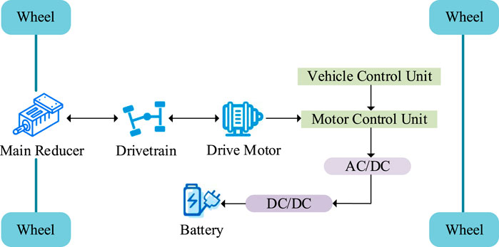
Figure 1. Schematic diagram of braking energy recovery.
As shown in Figure 1, during the entire process, the drive motor acts as a generator unit, efficiently recovering vehicle kinetic energy and converting it into electrical energy. This improves overall vehicle efficiency and extends the driving range. During the process of braking energy recovery, the motor is required to dynamically switch modes and finely regulate power output under complex operating conditions, with its control being affected by multiple factors such as vehicle speed, battery state, and braking force intensity. Therefore, the study first designs a fuzzy controller and defines membership functions to achieve adaptive control of the regenerative braking ratio under multiple input variables. A vehicle dynamics model is constructed to characterize the effects of multiple resistance forces on vehicle motion during braking, and the critical components influencing energy recuperation in regenerative braking are also systematically modeled. The power balance expression for the vehicle is shown in Equation 1.
In Equation 1,
In Equation 2,
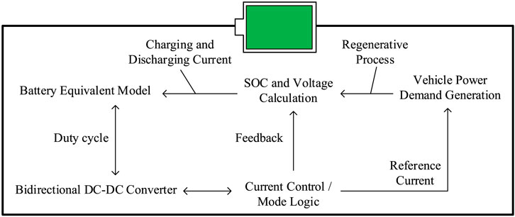
Figure 2. Schematic diagram of battery charging and discharging structure.
From Figure 2, during regenerative braking, the motor converts the braking energy into electrical energy to charge the battery. The battery’s state of charge (SOC) is updated using the integration method, with the specific expression shown in Equation 3.
In Equation 3,
In Equation 4,
In Equation 5,
In Equation 6,
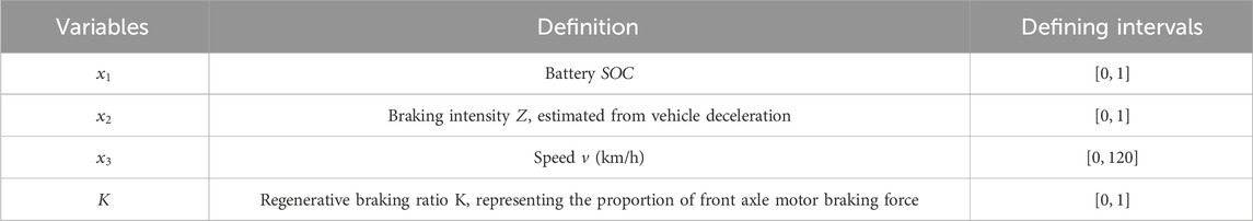
Table 1. Controller input and output variables.
In Table 1, the definitions of these input and output variables provide the foundation for the fuzzy controller’s design. The controller aims to adjust the regenerative braking ratio in real-time based on the vehicle’s actual operating conditions, maximizing energy recovery and ensuring smooth braking. The variables in the controller are set and described, and to help the fuzzy controller adapt to complex conditions like vehicle speed, braking intensity, and battery SOC, a Type-2 Gaussian membership function is used to finely describe the input. The advantage of Type-2 is that it can accurately describe the precision of input variables under uncertainty and noise interference. Therefore, Type-2 is adopted to help the fuzzy controller adapt to complex conditions, and the form of the Type-2 Gaussian membership function is shown in Equation 7.
In Equation 7,
In Equation 8,
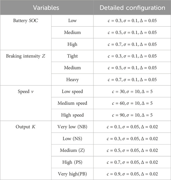
Table 2. Specific parameter settings.
In Table 2, based on variables under different conditions, the study constructs 27 rules in the form of “if … then …”. The braking intensity is classified into three levels:
In Equation 9,
In Equation 10,
3.2 Improved control algorithm and regenerative braking strategy based on PSO
After selecting the input and output variables and designing the Type-2 fuzzy membership functions, the study further constructs a specific fuzzy rule base. However, relying solely on manually set membership function parameters and rule weights often cannot adapt to the complex and changing real-world conditions. PSO can search for the optimal parameter combination globally, thus improving the overall performance of the fuzzy control system. Therefore, to enhance the generalization ability and output accuracy of the fuzzy controller, the study introduces PSO for offline optimization of the controller’s parameters. The fuzzy controller output is used for front axle braking force distribution. First, the total front axle braking force
In Equation 11,
In Equation 12,
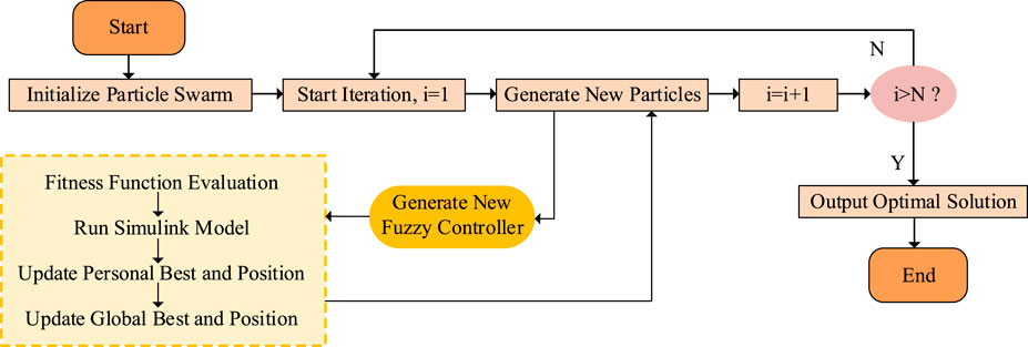 N), the optimal solution is output and the process ends; otherwise, it repeats. A subprocess involves running a Simulink model and generating a new fuzzy controller." id="F3" loading="lazy">
Figure 3. PSO process of fuzzy controller.
In Figure 3, after each particle swarm update during the optimization process, a simulation verification is performed using the Simulink model. Through this process, Simulink and the particle swarm optimization algorithm are tightly integrated, ensuring that each optimization iteration adjusts the control strategy based on simulation data, ultimately achieving optimal system control. Each particle represents a parameter vector, which is encoded as
In Equation 13,
In Equation 14,
In Equation 15,
In Equation 16,
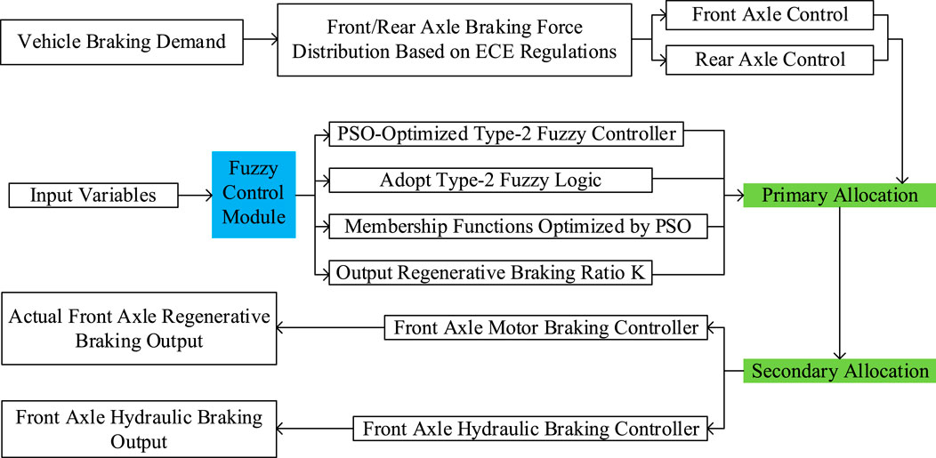
Figure 4. Workflow of regenerative braking fuzzy control strategy.
In Figure 4, first, based on the total vehicle braking demand, the braking force distribution plan for the front and rear axles is calculated according to ECE regulations. Then, the input variables are processed by the PSO-optimized Type-2 fuzzy controller. Type-2 fuzzy logic is used, and the membership function is optimized using the particle swarm algorithm to output the regenerative braking ratio
In order to enhance the generality of the proposed method, the fuzzy controller design and PSO-based optimization are developed in a modular and scalable framework, which can be adapted to other vehicle configurations or control targets. The selected parameters—membership functions, uncertainty bounds, and rule weights—are not specific to the studied vehicle model but represent universal fuzzy logic components that can be generalized across similar nonlinear control problems. Furthermore, the PSO optimization process is integrated with the Simulink simulation platform in a closed-loop structure, making it applicable to a broad range of model-based control design tasks beyond regenerative braking.
4 Simulation results of PSO-Fuzzy control strategy
4.1 Performance verification of braking strategy under different braking intensities
To verify the feasibility of the proposed strategy, a series of experimental setups were performed. The simulation platform used was MATLAB/Simulink, and the computer hardware configuration included an Intel Core i9-13900K processor, 64 GB DDR5 memory, NVIDIA GeForce RTX 4090 graphics card, a 1 TB NVMe SSD, and a 2 TB HDD for data storage. The system ran Windows 11, with an efficient cooling system and stable power supply to meet the high-performance requirements of MATLAB/Simulink co-simulation, complex model computation, and large-scale data processing. A full vehicle motion model was built in Simulink, along with a co-simulation system including a Type-2 fuzzy controller and PSO module. The specific parameters for the working conditions are shown in Table 3. It is worth noting that co-simulation refers to the integrated modeling of multiple subsystems—such as the vehicle dynamics model, energy management module, and braking control module—within the Simulink environment, enabling real-time coupling and interaction between the fuzzy control system and the PSO algorithm, thereby providing a more realistic simulation of system responses under actual operating conditions.
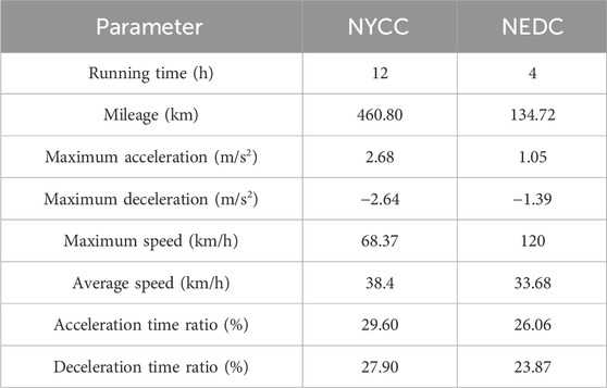
Table 3. NYCC and NEDC working conditions parameter table.
As seen in Table 3, the New York City Cycle (NYCC) and the New European Driving Cycle (NEDC) were selected as typical driving cycles. The energy recovery efficiency, braking performance, and control strategy indicators of the proposed strategy were validated. The PSO-Fuzzy control strategy was tested for braking times and distances under braking intensities of 0.2, 0.5, and 0.7, with results shown in Figure 5.
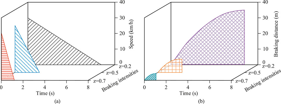
Figure 5. Braking time and braking distance under different braking intensities. (a) Braking time under different braking intensities (b) Braking distance under different braking intensities.
In Figure 5a, it can be seen that the higher the braking intensity, the faster the vehicle speed decreases and the shorter the braking time. For example, with a braking intensity of 0.7, the PSO-Fuzzy control strategy was able to reduce the speed from 40 km/h to 0 within 1.6s, responding quickly. In contrast, braking with intensities of 0.5 and 0.2 took 3.7s and 7.1s, respectively, to reach the same speed, showing a significant time disadvantage. The PSO-Fuzzy control strategy achieved quick deceleration at high speeds by dynamically adjusting the braking intensity, reducing braking time while maintaining a smooth braking process, making it especially suitable for urban emergency deceleration or mid-to-high speed scenarios. In Figure 5b, the strategy’s advantages were further validated from the perspective of braking distance. Under the same initial speed, the PSO-Fuzzy control strategy with an intensity of 0.7 allowed the vehicle to decelerate within 4.3 m, while the braking distances for intensities of 0.5 and 0.2 were 7.8 m and 35.1 m, respectively. Compared to fixed intensity braking, this strategy offered better braking accuracy and energy efficiency. These results demonstrate that the PSO-Fuzzy control strategy has the ability to dynamically adjust braking intensity according to actual conditions, ensuring safety, response speed, and energy recovery. Next, the SOC values and recovered energy were tested for braking intensities of 0.2 and 0.5, comparing the traditional braking strategy and the PSO-Fuzzy control strategy. The results are shown in Figure 6.
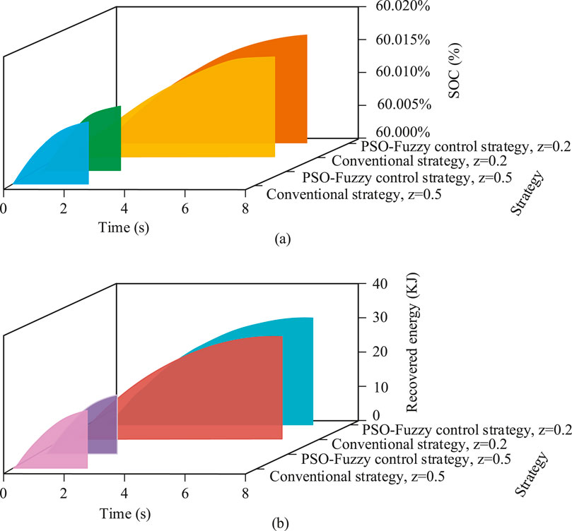
Figure 6. SOC value and regenerative energy under different braking intensities. (a) Battery state of charge status (b) Regenerative energy recovery status.
As shown in Figure 6a, there was little difference between the two strategies within the first second of braking. However, as time progressed, the PSO-Fuzzy control strategy showed a superior SOC improvement rate. When the braking intensity was 0.2, the strategy increased the SOC from 60.000% to 60.0016% within 2.4s, whereas the traditional strategy only increased it to 60.0012%. In Figure 6b, over time, the PSO-Fuzzy control strategy at z = 0.2 performed significantly better in energy recovery, accumulating 32 KJ of recovered energy within 8s, while the traditional strategy at the same intensity only recovered 27 KJ. Under the condition of z = 0.5, the PSO-Fuzzy control strategy also outperformed the traditional control. Overall, the results indicate that the PSO-Fuzzy control strategy achieved higher energy recovery efficiency and SOC improvement across different braking intensities, validating its comprehensive advantages in dynamic regenerative braking control. The different braking strategies were then introduced into the NYCC and NEDC driving cycles for comparison, as shown in Figure 7.
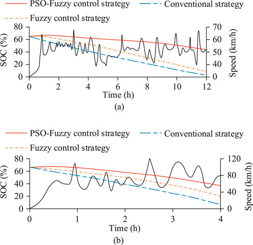
Figure 7. SOC changes under two working conditions. (a) SOC variation under NYCC cycle (b) SOC variation under NEDC cycle.
In Figure 7a, under the NYCC driving cycle, the SOC value for the traditional strategy continued to decrease, eventually dropping to 2.1%. In contrast, the proposed PSO-Fuzzy control strategy effectively suppressed SOC decline throughout the entire cycle, maintaining a smoother SOC curve, and at the end of the 12-h operation period, the SOC remained at 57.8%. This demonstrates that the strategy has higher energy recovery capacity and control stability in urban driving conditions with frequent stops, low speeds, and high-intensity braking. In Figure 7b, the NEDC cycle, which includes medium and high-speed driving with different acceleration and deceleration stages, showed a greater variation in SOC than the NYCC. Under the traditional strategy, the SOC dropped rapidly to 11.2% within 4 h, while the fuzzy control strategy was more stable, although the decline was still relatively fast. In contrast, the PSO-Fuzzy control strategy significantly delayed SOC decay, maintaining 47.6% throughout the entire simulation period, demonstrating its robustness and optimized control performance under complex, multi-stage conditions. In summary, although the control strategy exhibits good stability and convergence trends in simulation, future research will incorporate theoretical stability analysis of the closed-loop system to further enhance its robustness and convergence reliability under complex and dynamic operating conditions.
Additionally, by adopting a co-simulation architecture and separating the control algorithm from vehicle dynamics modeling, the proposed control strategy demonstrates potential applicability to different electric vehicle platforms and energy recovery systems. This modular structure ensures that the methodology can be extended to various intelligent vehicle control applications that involve nonlinear multi-objective optimization and uncertainty handling.
4.2 Braking performance analysis under NEDC conditions
Since the NEDC driving cycle combines various driving states, including urban and suburban driving, it realistically reflects vehicle braking response and energy recovery performance under complex conditions. Therefore, the braking performance of the control strategy under the NEDC cycle was analyzed separately in the simulation to evaluate the stability and robustness of the control strategy in low-speed steady-state and frequent acceleration-deceleration scenarios. The braking speed and braking intensity over a short period of time in the NEDC cycle were verified, with results shown in Figure 8.
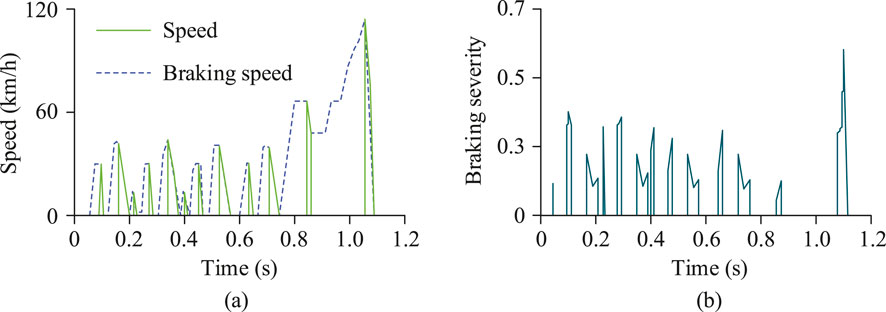
Figure 8. Braking speed and braking intensity in a short period of time. (a) Braking speed under NEDC driving cycle (b) Braking intensity under NEDC driving cycle.
In Figure 8a, the vehicle speed and braking speed under the PSO-Fuzzy control strategy were compared over time. In the multi-stage acceleration-deceleration interval from 0.4s to 0.8s, the two curves were relatively close, indicating that the strategy could quickly sense vehicle speed fluctuations and output precise braking intensity in real-time, bringing the vehicle to a complete stop at 1.2s, with a smooth deceleration process and no noticeable shocks. In Figure 8b, the PSO-Fuzzy control strategy made frequent adjustments between 0.1s and 0.6s, with more significant adjustments between 0.2s and 0.4s during the high-frequency braking phase. This shows that the strategy could adaptively adjust braking intensity according to vehicle speed, road conditions, and desired deceleration, avoiding excessive braking that would lead to energy waste while ensuring smooth and safe deceleration. Overall, the PSO-Fuzzy control strategy demonstrated precise and smooth braking process control through adaptive speed and braking intensity adjustments in the NEDC cycle. Finally, the research compared the driving range and K value optimization before and after the strategy optimization, as shown in Figure 9.
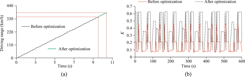
Figure 9. Optimization of driving range and K value. (a) Driving range under NEDC driving cycle (b) Regenerative braking ratio.
In Figure 9a, the driving range performance under the optimized strategy in the NEDC cycle was compared. Under the same energy consumption conditions, the vehicle under the optimized strategy was able to travel for a longer time and with more stable speed control. The final driving range increased from 342 km before optimization to 396 km, a 15.8% increase. In Figure 9b, the traditional strategy showed relatively stable but lower K values, mostly concentrated between 0.08 and 0.47, making it difficult to quickly adjust energy recovery intensity for different conditions. In contrast, the optimized PSO-Fuzzy control strategy showed frequent fluctuations, with a dynamic range covering from 0.08 to 0.63. In typical segments such as from 100s to 300s, where frequent acceleration and deceleration alternated, the strategy demonstrated significant adaptive adjustment ability. This strategy increased K values under conditions with high energy recovery potential to enhance energy recovery and appropriately reduced K values during stages when the SOC was higher or stability was more critical, effectively ensuring the balance between braking smoothness and energy management.
5 Conclusion
Although various advanced methods have been widely adopted, the current regenerative braking technology for electric vehicles still requires a balance between improving energy recovery efficiency and ensuring braking safety. Based on this, the study proposes a Type-2 fuzzy control strategy optimized by PSO to achieve optimal distribution of front axle braking force. At a braking intensity of 0.2, the PSO-Fuzzy control strategy required 7.1s to bring the vehicle, traveling at 40 km/h, to a stop. In 8s, it recovered 32 KJ of energy. In comparison, the traditional strategy increased the SOC value to 60.0012% in 2.4s, while the PSO-Fuzzy control strategy achieved a slightly higher increase to 60.0016%. Experimental results showed that the proposed control strategy successfully realized a dual optimization of energy recovery and braking safety. However, the current model is still sensitive to uncertainties under complex and extreme driving conditions, which need further reduction. Future work will introduce an online adaptive mechanism and real-vehicle testing to verify the strategy, aiming to achieve higher robustness and energy efficiency optimization under a wider range of driving conditions.
Data availability statement
The original contributions presented in the study are included in the article/supplementary material, further inquiries can be directed to the corresponding author.
Author contributions
CL: Writing – review and editing, Writing – original draft.
Funding
The author(s) declare that financial support was received for the research and/or publication of this article. The research is supported by Shandong Province University Future Industry Engineering Research Center, New Energy Vehicle Intelligent Network Technology Engineering Research Center, Platform ID: PT2025KJS003; Dezhou Key Laboratory Construction Project, Dezhou Electric Vehicle Power Control and Debugging Key Laboratory, Project Number: 6.
Conflict of interest
The author declares that the research was conducted in the absence of any commercial or financial relationships that could be construed as a potential conflict of interest.
Generative AI statement
The author(s) declare that no Generative AI was used in the creation of this manuscript.
Publisher’s note
All claims expressed in this article are solely those of the authors and do not necessarily represent those of their affiliated organizations, or those of the publisher, the editors and the reviewers. Any product that may be evaluated in this article, or claim that may be made by its manufacturer, is not guaranteed or endorsed by the publisher.
References
Agcal, A., Ozcira, S., Gokcek, T., Bekiroglu, N., Obdan, H., and Erdinc, O. (2023). A novel closed-loop frequency control approach for wireless power transfer systems in on-road electric vehicles. IEEE Trans. Intelligent Transp. Syst. 24 (12), 15300–15309. doi:10.1109/tits.2023.3308968
Chen, J., Hu, H., Wang, M., Ge, Y., Wang, K., Huang, Y., et al. (2024). Power flow control-based regenerative braking energy utilization in ac electrified railways: review and future trends. IEEE Trans. Intelligent Transp. Syst. 25 (7), 6345–6365. doi:10.1109/tits.2024.3350743
Gupta, G., Sudeep, R., Ashok, B., Vignesh, R., Kannan, C., Kavitha, C., et al. (2024). Intelligent regenerative braking control with novel friction coefficient estimation strategy for improving the performance characteristics of hybrid electric vehicle. IEEE Access 12 (6), 110361–110384. doi:10.1109/access.2024.3440210
Hentout, A., Maoudj, A., and Kouider, A. (2024). Shortest path planning and efficient fuzzy logic control of Mobile robots in indoor static and dynamic environments. Sci. Technol. 27 (1), 21–36. doi:10.59277/romjist.2024.1.02
Kumar, A., Singh, B., and Singh, G. (2023). Modified direct torque control of solar fed sensorless switched reluctance motor drive for electric vehicle with regenerative braking. IEEE Trans. Industry Appl. 60 (2), 3155–3164. doi:10.1109/tia.2023.3330452
Pasupuleti, S. S., Tummuru, N. R., and Misra, H. (2023). Power management of hybrid energy storage system based wireless charging system with regenerative braking capability. IEEE Trans. Industry Appl. 59 (3), 3785–3794. doi:10.1109/tia.2023.3234231
Precup, R. E., David, R. C., Roman, R. C., Szedlak-Stinean, A. I., and Petriu, E. M. (2023). Optimal tuning of interval type-2 fuzzy controllers for nonlinear servo systems using slime mould algorithm. Int. J. Syst. Sci. 54 (15), 2941–2956. doi:10.1080/00207721.2021.1927236
Sandrini, G., Gadola, M., Chindamo, D., and Magri, P. (2023). Efficient regenerative braking strategy aimed at preserving vehicle stability by preventing wheel locking. Transp. Res. procedia 70 (21), 28–35. doi:10.1016/j.trpro.2023.10.005
Senapati, M. K., Al Zaabi, O., Al Hosani, K., Ai Jaafari, K., Pradhan, C., and Muduli, U. R. (2024). Advancing electric vehicle charging ecosystems with intelligent control of DC microgrid stability. IEEE Trans. Industry Appl. 60 (5), 7264–7278. doi:10.1109/tia.2024.3413052
Shen, Y., Xie, J., He, T., Yao, L., and Xiao, Y. (2023). CEEMD-Fuzzy control energy management of hybrid energy storage systems in electric vehicles. IEEE Trans. Energy Convers. 39 (1), 555–566. doi:10.1109/tec.2023.3306804
Soltani, S. (2024). Enhanced estimation for direction of arrival calibration based on fusion of fuzzy Type-2 weighted iterative learning control. IEEE Trans. Industrial Inf. 21 (2), 1567–1575. doi:10.1109/tii.2024.3485760
Tempone, G. P., de Carvalho Pinheiro, H., Imberti, G., and Carello, M. (2024). Control system for regenerative braking efficiency in electric vehicles with electro-actuated brakes. SAE Int. J. Veh. Dyn. Stab. NVH 8 (10), 265–284. doi:10.4271/10-08-02-0015
Tristano, M., Lenzo, B., Xu, X., Forrier, B., D’hondt, T., Risaliti, E., et al. (2024). Hardware-in-the-loop real-time implementation of a vehicle stability control through individual wheel torques. IEEE Trans. Veh. Technol. 73 (4), 4683–4693. doi:10.1109/tvt.2024.3364151
Keywords: Simulink co-simulation, Type-2 fuzzy control, particle swarm optimization, electric vehicles, regenerative braking, energy recovery
Citation: Liu C (2025) Particle Swarm optimization of Type-2 fuzzy control for regenerative braking of electric vehicles. Front. Mech. Eng. 11:1612690. doi: 10.3389/fmech.2025.1612690
Received: 16 April 2025; Accepted: 25 July 2025;
Published: 12 August 2025.
Edited by:
Evangelos G. Giakoumis, National Technical University of Athens, GreeceReviewed by:
Saikat Dutta, University of Leeds, United KingdomRadu-Emil Precup, Politehnica University of Timişoara, Romania
Copyright © 2025 Liu. This is an open-access article distributed under the terms of the Creative Commons Attribution License (CC BY). The use, distribution or reproduction in other forums is permitted, provided the original author(s) and the copyright owner(s) are credited and that the original publication in this journal is cited, in accordance with accepted academic practice. No use, distribution or reproduction is permitted which does not comply with these terms.
*Correspondence: Chunhui Liu, MTg5NTM0NjUwODlAMTYzLmNvbQ==