 Longhai Ye
 Yanpeng Zhao
 Haifeng Zhang
- Flight College, Anyang Institute of Technology, Anyang, Henan, China
Introduction: With the booming low-altitude economy, UAVs drive transformative changes across sectors, but their design must balance lightweight demands and structural integrity. This study conducts static analysis of a quadrotor under hovering, using two optimization methods to enhance performance.
Methods: Two strategies were adopted: mass-constrained structural optimization (maintaining original mass) and unconstrained stiffener optimization (maximizing stiffness/strength without mass limits).
Results: Mass-constrained optimization reduced max von Mises stress by 38.8% and displacement from 6.49 mm to 5.91 mm. Unconstrained stiffener optimization achieved 5.2% mass reduction, 60.9% stress reduction, and displacement down to 1.63 mm.
Discussion: Both methods maintain structural strength and boost payload capacity. The stiffener optimization (reinforced rib design) provides a practical solution for heavy-load quadrotor engineering.
1 Introduction
With the rapid advancement of UAV technology in areas such as military reconnaissance, transportation, and emergency response, quadrotor UAVs are progressing toward higher payload capacity, extended endurance, and reduced structural weight. Their applications have transitioned from consumer-grade recreational devices to industrial-grade platforms, imposing stricter requirements on airframe structural integrity (Yu, 2017; Pei, 2019). Industry forecasts predict that the global industrial UAV market will grow at a compound annual rate of 13.8% between 2020 and 2025. The deployment of heavy-lift UAVs has notably increased in sectors such as agricultural management, crop protection, and power line inspection. Concurrently, structural failures account for up to 37.6% of flight accidents, indicating that conventional design methodologies are insufficient for addressing the demands of complex operational scenarios (Yu, 2017; Pei, 2019; Zhang, 2020). This mismatch between application requirements and design capabilities is even more evident in UAVs with unconventional configurations. For instance, tail-sitter VTOL UAVs demand high structural stiffness during hover while requiring aerodynamic efficiency in cruise. However, their arm connection points are prone to stress concentration, making them vulnerable to catastrophic failure (Zhang, 2020; Wang, 2019). Although carbon fiber composites are widely recognized for their high specific strength, most existing research has focused on single-material systems. Comparative studies involving hybrid systems—such as carbon fiber–aluminum alloy combinations—remain limited, potentially leading to performance compromises or deficiencies (Zhao, 2020; Gao, 2018).
Airframe strength is a fundamental physical parameter in ensuring flight safety. Effective structural strength design can significantly enhance both the performance and cost-efficiency of UAVs.
C. Pany et al. discussed the free vibration of periodic shells under various edge boundary conditions using finite element method (Pany et al., 2021).
Gu Wenjie et al. developed a hexacopter agricultural UAV through extensive experimentation and structural refinement. The resulting design offers advantages including a lightweight airframe, structural reliability, operational simplicity, safety, ease of maintenance, and cost-effectiveness. The extensive application of carbon fiber materials significantly reduced the airframe’s weight while improving its structural strength (Gu et al., 2015).
Liu Feng et al. conducted an in-depth analysis of the carbon fiber structure in a quadrotor UAV. By optimizing the carbon fiber layout, the overall weight was effectively reduced, leading to enhanced performance (Liu et al., 2017).
Huang Jiahao et al. examined UAV design fwith respect to airframe materials, loading conditions, and assembly processes. Based on a two-dimensional honeycomb-topology structure, they selected high-elasticity, lightweight engineered wood as the frame material and designed a quadrotor airframe reinforced by an embedded composite of flexible carbon fiber and wood (Huang et al., 2017).
Borchardt J. K highlighted that UAV development has significantly accelerated the use of composite materials. Conventional materials are no longer adequate to satisfy UAV requirements for weight, strength, and durability. In contrast, composite materials, characterized by low density, high strength, and corrosion resistance, fulfill these demands. The study elaborated on trends in composite application, emphasizing their effectiveness in reducing airframe and wing mass, improving flight efficiency, and enhancing payload capacity (Borchardt, 2004).
Lee M. K. et al. designed the wing configuration of a high-altitude long-endurance UAV, which requires high strength and stiffness while maintaining minimal wing mass and extended endurance. Based on the performance characteristics of composite materials and the UAV’s flight and load-bearing requirements, a tailored wing configuration was proposed. Advanced design methodologies were employed to optimize both the configuration and layup scheme, satisfying aerodynamic and structural criteria. This design contributes to the promotion of composites in UAV applications and improves the performance of long-endurance high-altitude UAVs, offering theoretical guidance for wing design (Lee et al., 2010).
Yang J. M. developed a precise three-dimensional model of a UAV wing to evaluate stress and strain distributions under applied loads, verifying whether structural strength met design criteria. Modal analysis was then performed to determine natural frequencies and mode shapes, ensuring that resonance would not occur during flight (Yang, 2012).
Sullivan R. W. et al. carried out structural and experimental investigations on an ultralight UAV carbon fiber composite wing. Theoretical modeling and finite element analysis were used to assess loading conditions, stress–strain responses, and deformation under various scenarios. Experimental validation, including static and fatigue testing, confirmed the theoretical predictions. Comparative analysis facilitated structural improvements, ensuring reliability and safety, and providing a bdesign reference for carbon fiber composite wings in ultralight UAVs (Sullivan et al., 2012). Many scholars have conducted systematic research on the structural optimization of unmanned aerial vehicles, focusing on achieving lightweight design through topology optimization methods, and combining the characteristics of composite materials to complete strength analysis and structural improvement. The relevant achievements provide important support for the structural design of various types of unmanned aerial vehicles such as quadcopters and fixed wings . These studies cover optimization dimensions from key components such as the fuselage and wings to the overall structure, effectively balancing the weight reduction and mechanical performance requirements of unmanned aerial vehicles (Yang, 2019, Dai, 2019; Xiong et al., 2023; Chai et al., 2016; Kuai and Wang, 2018; Feng and Gao, 2018; Zhao, 2019; Liu et al., 2019; Han, 2011; Ji et al., 2019; Liu et al., 2018; Li et al., 2023).
This study focuses on quadcopter unmanned aerial vehicles and conducts load calculations under extreme hovering conditions for heavy loads. Determine the strength and stiffness of the aircraft body through the initial cloud map. Conduct comparative analysis and research on two schemes: mass conservation structural optimization and reinforcement design optimization. The ultimate goal is to reduce weight and increase efficiency, and a reinforced rib design scheme is adopted to optimize the structure of the drone, in order to achieve the effect of reducing the weight of the drone, improving the strength and stiffness of the fuselage, and meeting the requirements of heavy loads.
2 Research object and methods
2.1 Research object
According to Figure 1, a quadrotor UAV model is established, with the main structure consisting of the drone body, rotor arms, rotors, and landing gear. Its overall structural feature is a cross-shaped symmetrical arrangement, with a maximum load capacity of 40 kg, meeting the balance requirements during hoisting and hovering.

Figure 1. Uav model.
2.1.1 Structural parameter settings
The central fuselage of the UAV is constructed from upper and lower plates composed of T700 carbon fiber. As the scope of this study is limited to the fuselage structure, components such as the central battery and flight control systems are excluded. Detailed specifications are provided in Table 1, Its length, width, and height are 796 mm, 670 mm, and 60 mm respectively. It is made using a composite material paving method, with a total of 4 layers and a total thickness of 2.595 mm.

Table 1. Central fuselage parameters.
The UAV arms are also fabricated from T700 carbon fiber and consist of four arms arranged symmetrically. Each arm is secured to the fuselage using two M8 bolts and one M12 bolt. Corresponding parameters are presented in Table 2, Its length is 540 mm, outer diameter is 45 mm, and wall thickness is 0.9 mm.

Table 2. Arm parameters.
The connectors, functioning as interfaces between the fuselage and arms, as well as between the arms and fixed rotors, require materials with high mechanical performance. Consequently, 6061-T6 aerospace-grade aluminum alloy was selected. These connectors are categorized into Groups A and B, comprising a total of eight units. Detailed specifications are provided in Tables 3, 4. Connector A serves as the carrier between the arm and the fixed rotor, with Hole A in its structure for connecting to the arm and Hole B for connecting to the rotor, as shown in Figure 2a. Connector B is the carrier between the fuselage and the arm, with Hole A in its structure for connecting to the arm, and Holes B and C serving as M12 and M8 bolt connection holes, respectively, as shown in Figure 2b.

Table 3. Connector a parameters.
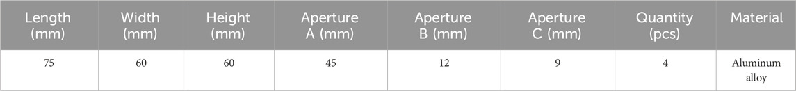
Table 4. Connector B parameters.
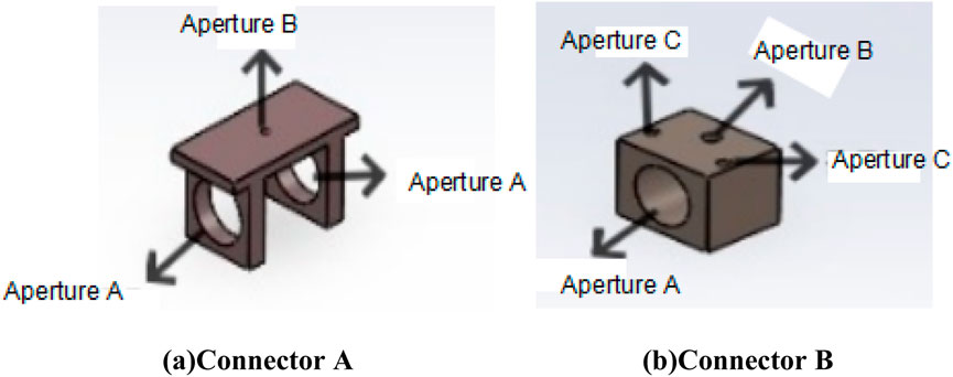
Figure 2. Connector. (a) Connector A. (b) Connector B.
2.1.2 Material property settings
The selection of the three primary materials for the UAV structure was guided by mechanical performance, weight reduction requirements, and manufacturing process compatibility. In this study, T700 carbon fiber composites were utilized for the fuselage and arms due to their superior strength and fatigue resistance. For the connectors, 6061-T6 aerospace-grade aluminum alloy was employed owing to its favorable yield strength and machinability. Specific parameters are listed in Table 5.
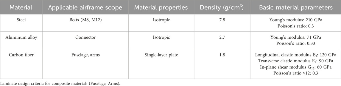
Table 5. Material properties of UAV components.
2.1.3 The primary design principles for composite laminates are outlined as follows
Balanced Symmetry Principle: To prevent warpage deformation induced by torsion–bending coupling, laminates should preferably adopt balanced and symmetric layup configurations.
Ply Orientation Principle: Based on the fundamental requirement of meeting structural load-bearing demands, the number of ply orientations should be minimized. This approach simplifies the design of angular variables and reduces the complexity of fabrication. Standard ply angles of 0°, 90°, and ±45° should be widely employed.
Minimum Ply Percentage Principle: To avoid direct load transfer to the matrix and to mitigate stress induced by moisture and temperature variations, each of the principal ply orientations (0°, 90°, and ±45°) should account for no less than 6%–10% of the total laminate.
Ply Sequence Principle: The number of consecutive plies at corners within the same laminate layer should generally not exceed four to reduce the likelihood of interlaminar edge delamination and bidirectional cracking. For composite structures incorporating ±45°, 0°, and 90° plies, layups combining 0° or 90° plies with +45° or −45° plies should be prioritized to minimize interlaminar stresses. In contrast, combinations of 90° with +45°, particularly with only −45°, as well as layups lacking 0° plies, should be avoide. This is because 0° plies provide superior load-bearing capacity along the longitudinal direction of the high-strength fibers, and increasing their proportion ensures full exploitation of the material’s primary strength. Conversely, 90° plies, oriented transversely to the strong fiber direction, enhance the laminate’s transverse strength and aid in tuning Poisson’s ratio. Similarly, +45° plies, oriented at 45° to the fiber axis, contribute to Poisson’s ratio adjustment and improve transverse strength. The ±45° plies additionally resist in-plane shear stresses and, when placed on the outermost layers, enhance compressive strength and impact resistance.
Based on these principles, a layup scheme was developed for the fuselage of the quadrotor UAV. The corresponding layup parameters are shown in Table 6.
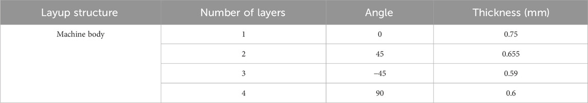
Table 6. Fuselage layup parameters.
The arm components adopt the same layup configuration as the fuselage, with detailed parameters presented in Table 7.
Table 7. Arm layup parameters.
2.1.4 Other parameter settings
The quadrotor UAV analyzed in this study has a mass of 7.30 kg and a maximum payload capacity of 40 kg. The boundary condition is defined by a hovering constraint, wherein a fixed constraint is applied to the central surface of the fuselage load-bearing module. The hovering overload is specified as 2 g. Lift forces are applied vertically at the extremities of each arm. Considering both the overload factor and the safety factor, the loading criteria are defined as follows:
2. The total mass of the UAV, denoted as M, includes both the structural mass and the payload capacity, and is expressed as:
M — Total Mass; M1 — UAV Self-Mass; M2 — Maximum Payload Capacity of the UAV.
2. The total weight under hovering overload conditions is computed by accounting for the overload factor, as given by:
F1 — Total Overload Weight of the UAV during Hovering; k — Overload Factor, taken as 2; g — Gravitational Acceleration, taken as 9.8 N/kg.
3. The total load incorporating the safety factor is determined as:
F2 — Total Load under Safety Factor Consideration; n — Safety Factor, taken as 1.5.
4. The lift force required per rotor is given by:
F3 — Lift Required by a Single Rotor; p — Number of Rotors, taken as 4
Based on the above calculations, apply (Equations 1–4), each rotor is required to generate a lift force of F3 = 347.655 N.
2.2 Research method
Considering the dynamic aerodynamic load characteristics of the cantilever support structure of quadcopter unmanned aerial vehicles, the inertia release method is used to analyze the static equilibrium problem of free bodies.
As shown in Figure 3a,The porous pore structure and morphology of the fuselage, as the main load-bearing body, pose a dual challenge to the grid quality in this article. Based on the characteristics of carbon fiber laminates, a layered shell element is established to obtain higher quality and higher strength carbon fiber composite material mesh sizes. The fiber direction of each layer is defined through the material’s coordinate system, and the transition zone of the layer is replaced by a gradient mesh density instead of a sudden stiffness change. The basic minimum cell is set to 0.1 mm. As shown in Figure 3b,To ensure the accuracy of the calculation, the arm adopts the same mesh division method as the fuselage. As shown in Figure 3c,The grid strategy for connectors requires a balance between contact nonlinearity and computational efficiency. Use tetrahedral element type for mesh division of the connecting components at the bolted joint.

Figure 3. Mesh of UAV. (a) Fuselage mesh. (b) Arm mesh. (c) Connector mesh.
The contact surface of the bolt connection is constrained using a binding constraint, the material constitutive model adopts an ideal elastic-plastic model, and the minimum grid size is set to 0.5 mm. The bolted connection adopts rigid binding constraints, which are set to ensure that the displacement and rotation of the contact surface between the bolt and the connected part are completely consistent, and there is no relative deformation between the contact surfaces, equivalent to a “fixed connection” state. This article mainly analyzes and optimizes the structural strength of unmanned aerial vehicle (UAV) bodies. Therefore, the influence of bolts and connectors is simplified, and the model is replaced by a cylindrical shape without applying pre tension force. The ideal elastic-plastic model is used for setting, and the specific parameters are shown in Table 5. The yield strength is 640 MPa, the yield strain is 3.05 * 10–3, and the ideal elastic-plastic curve is shown in the Figure 4.
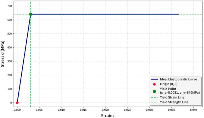
Figure 4. Ideal elastoplastic curve of bolt.
The center position of the fuselage is completely fixed, constraining full translational and rotational degrees of freedom.
Static structural analysis of the original UAV model reveals a maximum von Mises stress of 309.2 MPa and a peak displacement of 6.49 mm, indicating significant stress concentration and structural rigidity under extreme operating conditions. As shown in Figure 5, the highest stress occurs at the junction between the arms and the fuselage, with a value of 309.2 MPa. The corresponding maximum displacement, shown in Figure 6, is 6.49 mm.
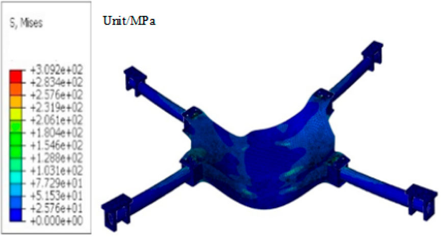
Figure 5. Initial stress cloud diagram of UAV.
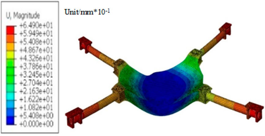
Figure 6. Initial displacement cloud diagram of UAV.
Based on the static analysis results of the quadcopter drone under hovering conditions, two methods of structural optimization were adopted: mass-constrained structural optimization and unconstrained stiffener optimization. The workflow diagram is shown in Figure 7.

Figure 7. Workflow diagram for structural optimization.
2.2.1 Scheme I: Mass-constrained structural optimization design
Scheme I is based on the design principle of synergistically optimizing both weight reduction and structural strength for the quadrotor UAV airframe. A composite strategy of “localized thickening with global perforation” is employed. Starting from a homogeneous fuselage model and leveraging the strength and mass redundancies identified in the preliminary analysis, reinforcement was applied to critical stress regions, particularly the arm junctions and the central load-bearing section of the fuselage. Concurrently, a porous topology was implemented in low-stress zones, introducing honeycomb-style perforations. A parameterized hole array facilitated dynamic mass redistribution and balance.
Optimization of Critical Fuselage Regions: Referring to the initial model, areas subject to high stress were selectively thickened. The thickness in these regions was increased from the baseline composite value of 2.595 mm–3.13 mm, while the thickness of other components remained unchanged.
Optimization of Remaining Fuselage Sections: Based on the initial stress distribution map, regions exhibiting low stress were selected for perforation using a topological optimization approach, as illustrated in Figure 8.
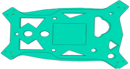
Figure 8. Fuselage after perforation.
With increasing fuselage thickness, both the structural strength and stiffness of the optimized airframe exhibited significant improvement. As shown in Figure 9, the maximum von Mises stress in the optimized fuselage reached 189.2 MPa, indicating a 38.8% decrease compared to the original value of 309.2 MPa. According to the deformation analysis shown in Figure 10, the maximum displacement during hovering flight was 5.91 mm, representing an 8.9% reduction from the initial design value of 6.49 mm.
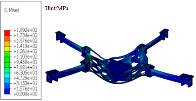
Figure 9. Stress cloud diagram of mass-conserving optimized fuselage.
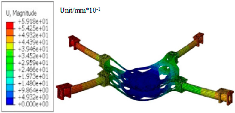
Figure 10. Displacement cloud diagram of mass-conserving optimized fuselage.
2.2.2 Scheme II: unconstrained stiffener optimization
While Scheme I achieved a 38.8% reduction in maximum von Mises stress, its constraint of mass conservation limited its effectiveness in reducing overall weight. To address this, Scheme II introduces an enhanced reinforcement strategy aimed at simultaneously improving structural load-bearing capacity and achieving mass reduction. This dual objective offers a new pathway for both lightening UAV development and performance enhancement.
Scheme II is grounded in the principles of structural topology optimization and adopts a strategy combining cross stiffeners with fuselage thinning to optimize the quadrotor UAV fuselage. This integrated approach improves structural strength while reducing overall mass. Cross stiffeners are strategically positioned in the primary load-bearing zones and aligned with principal stress transfer paths to mitigate bending and torsional deformations occurring during flight. The extent of skin thinning in non-critical load-bearing areas is determined through topology optimization. Parametric mapping is subsequently employed to correlate structural thickness with stress distribution, enabling the identification of controlled stiffener locations and ensuring optimal load-bearing performance under the specified local buckling critical load conditions.
2.3 Stiffener configuration parameters
1. Based on preliminary analysis, stiffeners are located in regions of high stress concentration within the central plate.
2. The stiffeners are fabricated using T700 carbon fiber/epoxy prepreg laminates with ply orientations of [0°, 45°, −45°, 90°] and individual layer thicknesses of 0.6 mm, 0.3 mm, 0.3 mm, and 0.3 mm, respectively. Each stiffener measures 60 mm in height and 300.5 mm in width, and is co-cured with the base fuselage structure.
3. The final stiffener dimensions are 293 mm in length, 15 mm in width, and 60 mm in height, ensuring full integration with the UAV structure. A schematic representation is provided in Figure 11.

Figure 11. Schematic diagram of stiffener.
Fuselage Parameter Optimization: In the non-critical load-bearing regions of the fuselage, a thickness reduction strategy was implemented, decreasing the original thickness from 2.595 mm to 1.9 mm, while maintaining the thickness of other components.
As a result of the optimization, the structural mass was reduced from 7.30 kg to 6.92 kg, corresponding to a 5.2% weight reduction, indicating that topology optimization effectively satisfies the structural lightweight design requirements.
The incorporation of cross-shaped stiffeners redefined the load-transfer path within the fuselage. Under hovering conditions, bending stresses are redirected through the stiffeners toward the support points, thereby mitigating localized stress concentrations. As shown in Figure 12, strength analysis reveals that the maximum von Mises stress decreased from 309.2 MPa to 120.9 MPa following optimization, representing a 60.9% reduction. The optimized fuselage exhibits negligible stress concentration, fulfilling the objective of topology optimization in redesigning load-transfer pathways. Additionally, as illustrated in Figure 13, the maximum hovering displacement decreased from 6.49 mm to 1.63 mm, indicating a 74.8% improvement in stiffness. This optimization thus enhances both the strength and stiffness of the fuselage.

Figure 12. Stress cloud diagram of fuselage with stiffener design optimization.

Figure 13. Displacement cloud diagram of fuselage with stiffener design optimization.
2.3.1 Comparative analysis of the two schemes
Based on the data presented in Table 8, stiffener design optimization exhibits a distinct advantage in mass control. The structural material of the fuselage has a strength of 230 MPa. Although both optimization schemes meet its strength requirements, Scheme 1 only has a strength safety margin of 40 MPa, which is 17.7% of the total strength limit. After optimization in Plan 2, the remaining strength safety margin is 110 MPa, which is 47.8% of the total strength limit.
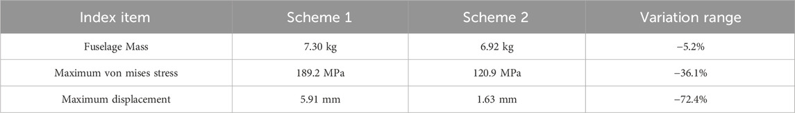
Table 8. Comparison of fuselage performance parameters before and after optimization.
While Scheme I maintained mass equilibrium through fuselage perforation, it failed to achieve a meaningful reduction in structural weight. In contrast, Scheme II, which integrates fuselage thinning with stiffener reinforcement, reduced fuselage mass by 0.38 kg without compromising performance, thereby enhancing the UAV’s overall payload capacity. Furthermore, Scheme II led to more pronounced improvements in both structural strength and stiffness. Compared to Scheme I, this approach capitalized on the mechanical advantages of cross stiffeners in combination with fuselage thinning, establishing an efficient load-transfer pathway. Consequently, the stress distribution under identical loading conditions became more uniform, with the maximum von Mises stress reduced by approximately 36.1% and deformation decreased by 72.4%, indicating superior overload resistance and structural stability.
Experimental results confirm that Scheme II surpasses the mass-conserving approach in terms of enhancing strength and stiffness, controlling mass, and optimizing overall performance. It better satisfies the design criteria for quadrotor UAVs requiring lightweight structures and high performance under high-overload and heavy-payload conditions, making it a more favorable option for subsequent engineering applications.
3 Conclusion
This study conducted strength analysis and structural optimization based on a quadrotor UAV with a hovering overload capacity of 2 g and a maximum payload of 40 kg. The key findings are summarized as follows:
1. Under extreme hovering conditions (2 g overload and 40 kg payload), strength analysis of the original fuselage structure revealed a mass of 7.30 kg, a peak stress of 309.2 MPa, and a maximum displacement of 6.49 mm. These results indicate pronounced stress concentration and deformation, with insufficient safety margins in critical structural regions.
2. Scheme I employed a mass-conserving optimization strategy. By locally thickening structural sections and incorporating weight-reduction holes, the fuselage mass remained constant. Meanwhile, the maximum von Mises stress was reduced to 189.2 MPa and the maximum displacement decreased to 5.91 mm, corresponding to reductions of 38.8% and 8.9%, respectively, thereby enhancing structural strength.
3. Scheme II adopted a reinforcement strategy involving the addition of stiffeners and plate thickness adjustments in specific areas. As a result, the fuselage mass decreased from 7.30 kg to 6.92 kg. The peak stress was reduced to 120.9 MPa (a 60.9% decrease), and the maximum displacement was limited to 1.63 mm (a 74.8% decrease).
4. Compared to Scheme I, Scheme II exhibited superior performance due to the synergistic effects of stiffener integration and optimized material distribution, enabling simultaneous weight reduction and structural enhancement. The fuselage mass was reduced by 5.2%, while the stress and displacement were decreased to 39.1% and 25.1% of the original values, respectively. Furthermore, the load-bearing capacity under heavy-load hovering conditions improved significantly. These results validate the feasibility of the “weight reduction with performance gain” concept in Scheme II and provide a practical design approach for quadrotor UAVs operating under heavy-load scenarios.
Although this study significantly improved the load-bearing performance of the drone body through static analysis and structural optimization, limited by the assumption of idealized operating conditions, future research can be further expanded in the following directions: it can further combine dynamic load types such as vibration and aerodynamic loads under drone flight conditions to lay a reliable means for predicting fatigue life and structural durability for long-term heavy load operations of drones.
Data availability statement
The original contributions presented in the study are included in the article/supplementary material, further inquiries can be directed to the corresponding author.
Author contributions
LY: Writing – original draft, Data curation, Writing – review and editing. YnZ: Formal Analysis, Writing – review and editing. HZ: Writing – review and editing, Methodology. YoZ: Formal Analysis, Writing – review and editing. JL: Conceptualization, Writing – review and editing. ZY: Writing – review and editing, Methodology.
Funding
The authors declare that financial support was received for the research and/or publication of this article. This work was supported by Henan Province College Students Innovation Training Program. (S202511330025).
Conflict of interest
The authors declare that the research was conducted in the absence of any commercial or financial relationships that could be construed as a potential conflict of interest.
Generative AI statement
The authors declare that no Generative AI was used in the creation of this manuscript.
Any alternative text (alt text) provided alongside figures in this article has been generated by Frontiers with the support of artificial intelligence and reasonable efforts have been made to ensure accuracy, including review by the authors wherever possible. If you identify any issues, please contact us.
Publisher’s note
All claims expressed in this article are solely those of the authors and do not necessarily represent those of their affiliated organizations, or those of the publisher, the editors and the reviewers. Any product that may be evaluated in this article, or claim that may be made by its manufacturer, is not guaranteed or endorsed by the publisher.
References
Borchardt, J. K. (2004). Unmanned aerial vehicles spur composites use. Reinf. Plast. 48 (4), 28–31. doi:10.1016/s0034-3617(04)00194-8
Chai, Y., Qin, C., Jiang, M., Zhou, J., Yang, S., and Ding, Z. (2016). Design and structural analysis of a novel quadcopter, 3. Yantai, China: Machine Design and Research, 47–50.
Dai, H. (2019). Structural design and strength analysis of a ten-kilogram-class civil composite fixed-wing UAV. Civ. Aviat. Flight Univ. China.
Feng, K., and Gao, J. (2018). Structural optimization design and analysis of a tethered UAV composite airframe. Fiber Reinf. Plastics/Composites 297 (10), 57–62.
Gao, H. (2018). Structural design and optimization of a micro carbon fiber quadrotor UAV. Guanghan, China: Civil Aviation Flight University of China.
Gu, W., He, Y., Wang, C., Cao, C., and Ge, Z. (2015). Structural design of a hexacopter pesticide-spraying UAV. J. Anhui Agric. Sci. 43 (31), 15–23.
Han, H. (2011). Finite element analysis and local structural design of a UAV wing based on ABAQUS. Changsha, China: National University of Defense Technology.
Huang, J., Wu, J., Zhang, C., and Zhang, S. (2017). Lightweight airframe structural optimization design of a multirotor UAV. Sci. Technol. Innovation Her. 12, 23–25.
Ji, L., Ding, W., Gu, C., Li, Y., Saeed, N., Chen, Z., et al. (2019). Structural design of a quadrotor UAV based on topology optimization. Comput. Aided Eng. 28 (03), 25–29.
Kuai, S., and Wang, W. (2018). Research on the design of a multirotor firefighting UAV. Fire Sci. Technol. 037 (6), 791–793.
Lee, M. K., Cho, C. M., and Jang, S. Y. (2010). HALE UAV composite wing structure design. Adv. Mater. Res. 123, 105–108. doi:10.4028/www.scientific.net/amr.123-125.105
Li, H., Yan, W., Chen, Y., Zhang, C., Liao, Z., Su, L., et al. (2023). Lightweight design of a quadrotor UAV fuselage based on topology optimization. Eng. Plast. Appl. 51 (02), 60–66.
Liu, F., Dai, H., Wang, K., and Gao, H. (2019). Design and stress analysis of an all-carbon fiber wing for a ten-kilogram-class fixed-wing UAV. Aerosp. Mater. and Technol. 49 (4), 50–55.
Liu, F., Gao, H., Yu, H., and Dai, H. (2017). Finite element-based structural optimization design and natural modal analysis of a quadrotor UAV with carbon fiber structure. Fiber Reinf. Plastics/Composites 04, 17–23.
Liu, F., Yu, H., Gao, H., Dai, H., and Ma, J. (2018). Structural optimization design and strength calculation of a heavy-load quadrotor UAV. Adv. Aeronautical Sci. Eng. 9 (01), 99–106.
Pany, C., Parthan, S., and Mukhopadhyay, M. (2021). Free vibration analysis of an orthogonally supported multi-span curved panel. J. Sound Vib. 241 (2), 315–318. doi:10.1006/jsvi.2000.3240
Pei, Y. (2019). Mechanical characteristics analysis of the transmission system of heavy-load quadrotor UAV. Shenyang, China: Shenyang University of Technology.
Sullivan, R. W., Hwang, Y., Raisrohani, M., and Lacy, T. (2012). Structural analysis and testing of an ultralight unmanned-aerial-vehicle carbon-composite wing. J. Aircr. 46 (3), 814–820. doi:10.2514/1.36415
Wang, B. (2019). Structural design and simulation analysis of jet-powered twin-rotor aircraft. Ma’anshan, China: Anhui University of Technology.
Xiong, T., Qian, B., Hu, Z., Mao, J., Zhao, M., and Liu, G. (2023). Topology optimization of a quadrotor UAV based on continuous fiber additive manufacturing process. Eng. Plast. Appl. 51 (10), 76–84.
Yang, J. M. (2012). Strength and modal analysis of the wing's configuration for UAV based on ABAQUS. Nanchang, China: Journal of Nanchang Hang kong University.
Yang, C. (2019). Weight reduction optimization of a small quadrotor UAV based on topology optimization method. Kunming, China: Kunming University of Science and Technology.
Yu, H. (2017). Design and strength calculation of heavy-load quadrotor civil UAV. Civ. Aviat. Flight Univ. China.
Zhang, Z. (2020). Structural design of tail-sitter vertical take-off and landing UAV. Zhengzhou, China: Henan University of Technology.
Zhao, Z. (2019). Preliminary structural design and strength analysis of a small long-endurance UAV. Harbin, China: Harbin Institute of Technology.
Keywords: UAV airframe, structural optimization, strength analysis, mass constraint, flight
Citation: Ye L, Zhao Y, Zhang H, Zhang Y, Lv J and Yang Z (2025) Strength analysis and structural optimization of UAV airframe. Front. Mech. Eng. 11:1708043. doi: 10.3389/fmech.2025.1708043
Received: 19 September 2025; Accepted: 10 November 2025;
Published: 01 December 2025.
Edited by:
Guorui Wang, University of Science and Technology of China, ChinaReviewed by:
Chitaranjan Pany, Vikram Sarabhai Space Centre, IndiaAlief Wikarta, Sepuluh Nopember Institute of Technology, Indonesia
Copyright © 2025 Ye, Zhao, Zhang, Zhang, Lv and Yang. This is an open-access article distributed under the terms of the Creative Commons Attribution License (CC BY). The use, distribution or reproduction in other forums is permitted, provided the original author(s) and the copyright owner(s) are credited and that the original publication in this journal is cited, in accordance with accepted academic practice. No use, distribution or reproduction is permitted which does not comply with these terms.
*Correspondence: Longhai Ye, WWxoMTQ3NjY2ODg4QDE2My5jb20=