 Rishabh Pal
 Vikrant Yadav
 Arijit Sharma
- 1Department of Physics, Indian Institute of Technology Tirupati, Yerpedu, India
- 2Center for Atomic, Molecular, and Optical Sciences and Technologies, Indian Institute of Technology Tirupati, Yerpedu, India
High finesse optical cavities have been the backbone of realizing narrow linewidth lasers to drive coherent excitations on dipole-forbidden transitions in atoms and ions for applications in atomic frequency standards. Over the past decade, increasing efforts have been made to develop technologies that enable the operation of all-optical atomic clocks in a portable form factor outside laboratory environments relying on transportable high-finesse optical cavities for field applications in positioning, navigation, timing (PNT) and communication. However, the compactness of such systems makes them more susceptible to environmental noises that limit their performance and stability. This review aims to address the underlying physics behind high-finesse optical cavities, cavity-based laser frequency stabilization schemes and various sources of noise arising from thermal, vibrational, acoustic, power and polarization fluctuations that impede the stability of portable optical cavities, as well as outline the strategies for minimizing their influences. We also discuss about the minimization of the residual amplitude modulation (RAM) noise that degrades the laser linewidth. In addition, our study encompasses a comparative analysis of various transportable, high-finesse optical cavity systems that are currently accessible for terrestrial and space-based metrology applications, as well as an exploration of the potential applications that these cavities can facilitate. We also review recent advancements in designing such systems and highlight their efforts for constructing ultra-stable, compact, high-finesse cavities for terrestrial and space-borne transportable all-optical atomic clocks.
1 Introduction
Atomic clocks have facilitated exceptional precision in timekeeping, a crucial requirement for global positioning system (GPS) and navigation systems (Boldbaatar et al., 2023), telecommunications and timestamping of financial transactions (Marlow and Scherer, 2021), and strategic applications (Vig, 1993). The unprecedented accuracy in time and frequency metrology offered by next-generation optical atomic clocks has ushered in a new experimental epoch in search for the physics beyond the standard model (BSM) (DeMille et al., 2017), investigating the temporal variation of the fundamental physical constants, search for the dark matter (DM) (Safronova et al., 2018), advancement in geodetic measurements (Mehlstäubler et al., 2018). These scientific endeavours depend on the extremely high accuracy and low instability offered by optical atomic clocks.
Enhanced precision in time measurement aided by narrow linewidth lasers stabilized to high-finesse optical cavities have ushered in a new era in frequency metrology. This has led to integrating such portable, ultra-stable cavities as payloads in satellites. Such payloads have enabled tracking of distances between two satellites in highly successful space missions like GRACE-FO1. The GRACE-FO mission has revealed interesting information by mapping the Earth’s gravitational field, measuring water and ice distribution over the Earth’s surface, and contributing the studies in geodesy and climate changes (Landerer et al., 2020; Tapley et al., 2019). The importance of such missions was appreciated and promoted further through future missions like NGGM2 (Nicklaus et al., 2017). The theory of general relativity (Misner et al., 2017), which is based on principles like local Lorentz invariance (LLI), Einstein’s equivalence principle, etc. (Rodrigues and Oliveira, 2016), can be tested by measuring the gravitational redshift using precision optical clocks in space owing to longer interrogation times in unperturbed space environments (Gill et al., 2008). Several space missions have been proposed for similar measurements, like STAR3 (Braxmaier et al., 2010), BOOST4 (Sanjuan et al., 2019), STE-QUEST5 (Altschul et al., 2015), SOC6 (Bongs et al., 2015), etc.
Lab-based lasers designed for coherently addressing the clock transition in stationary optical clocks outperform their counterparts made for portable clocks. For example, notable stationary clock laser systems developed by (Bothwell et al., 2019; Schwarz et al., 2020) demonstrate instability levels of approximately
The superior stability of lab-based optical clocks is attributed to the laser frequency stability that interrogates the clock transition. Such a laser is more stable than those in portable clocks as they leverage the advantage of being decoupled from the environment. Measurement of stability of a frequency standard is quantified by Allan deviation expressed as follows (Itano et al., 1993):
where
Laser frequencies are susceptible to drifts due to various environmental and operational factors like air pressure, humidity, temperature, acoustic noises, laser diode current, grating position, etc. As a result, the primary experimental challenge lies in developing robust control and feedback systems for these lasers to mitigate such environmental and technical disturbances and achieve a narrow linewidth with a low drift in frequency. This necessitates the requirement that lasers must be stabilised to highly stable references that surpass the intrinsic frequency stability of the laser itself (Fox et al., 2003). The chosen reference must be able to detect continuous changes in the quantity we aim to stabilize, such as frequency, phase, and polarization. Examples of references include atomic or molecular transitions (dipole-forbidden), frequency combs, optical cavities, etc. Clock transitions characterized by extremely narrow linewidth (
To realize a laser with frequency stability of about
However, operating a cavity with a longer length for transportable clock purposes poses a significant challenge in mitigating mechanical and other vibrational noises. For portable clocks, there is a necessary trade-off between optimizing cavity length to reduce the thermal noise floor and managing the practical challenges of transporting such systems. This trade-off limits the stability of portable optical clocks compared to state-of-the-art, lab-based systems. Furthermore, external temperature fluctuations influence the cavity length arising from thermal expansion. Local heating of the cavity surface due to thermal radiation emitted by the cavity housing also affects the optical path length (Dai et al., 2015). While these issues are better addressed in stationary cavities placed in well-controlled lab environments, significant challenges emerge when attempting to make these cavities transportable. Mitigating these challenges requires robust active temperature control systems which can withstand harsh operating environments.
The mechanical stability of the cavity is significantly affected by vibrational noise arising out of environmental and mechanical disturbances in the structure and mounting. Compared to stationary lab-based cavities (Millo et al., 2009), transportable cavities require a robust, rigid mounting structure to withstand rapid movements and acceleration during transport, which can introduce greater stress on the cavity and potentially result in changes in its length. This requirement also presents considerable challenges in mitigating vibrational noise (Häfner et al., 2020; Zhao et al., 2022). Therefore, careful considerations in designing control systems and robust housing are crucial for ensuring mechanical stability and operating portable cavities at room temperature. Subtle choices of cavity spacer material, mirror substrate, mirror coatings, and mounting material, in conjunction with excellent thermal and mechanical stability, become essential in developing a robust portable cavity that can only be limited by the thermal noise floor.
In addition to the above-mentioned issues, optical cavities meant for space-based missions need to meet more robust and rugged requirements, given the harsh outer space environment. Cavities onboard spacecraft would experience large accelerations and shocks during launch, requiring more rigorous mounting strategies (Tao and Chen, 2018; He et al., 2021). The size, weight, and power (SWaP) of the assembly are major factors that constitute the payload and directly affect the overall project cost. Compact breadboards must be integrated carefully for space optimization with rigidly attached optical components, demanding the miniaturization of optics. The space radiation in and around the Earth’s atmosphere can severely damage the electronic components and optics of the satellite onboard lasers. This radiation originates from various sources such as solar flares consisting of charged particles, high energy cosmic and gamma rays, and particles losing energy in the form of Bremsstrahlung or secondary X-rays7. The mirror coatings are also prone to space radiation, affecting the thermal noise floor and finesse of the cavity. To avoid radiation damage, sensitive optics (such as mirror coatings) and electronic components necessitate conducting radiation-hardened tests (Cole et al., 2024). In addition to all this, automation of electronics is required for space-borne optical cavities, which can be operated without human intervention for years.
This review article explores the challenges, obstacles, and strategies involved in the design and construction of high-finesse, ultra-stable, portable optical cavity systems. We also outline the significant developments in portable cavities over the past 2 decades. Such details are critical and essential for the development of portable optical clocks. A number of review articles and technical reports on optical clocks for both introductory and expert levels have been published erstwhile (Gill, 2005; Margolis, 2009; Riehle, 2015; Ludlow et al., 2015; Abdel-Hafiz et al., 2019). Recently (Boyd and Lahaye, 2024), published a pedagogical article on development of ultra-stable lasers.
We shall initiate a discussion on the basic principles of the cavity and delineate the geometrical criteria that such cavities must fulfil for achieving laser beam stability in Section 2. We shall follow it up with a brief discussion on the evolution of laser stabilization techniques for cavities in Section 3, subsequently exploring the theory of the PDH method, which is one of the most effective techniques. Thereafter, we delve into Section 4, where we discuss about different noise sources and their impact on cavity stability. We also outline the strategies to alleviate these noises and provide guidelines to develop an ultra-stable, high-finesse portable optical cavity. Since residual amplitude modulation (RAM) is a conglomeration of many effects, mainly arising due to the use of an electro-optic modulator (EOM) and is a major experimental hurdle in achieving stability below
2 Fabry-Pérot cavity
2.1 Introduction
An optical Fabry-Pérot (FP) resonator consists of two parallel mirrors separated by a distance that sustains standing waves determined by the cavity length. We discuss here only the important results and formulas. Detailed discussions can be found on cavities elsewhere (Silfvast, 2004; Milonni and Eberly, 2010). Figure 1 illustrates the schematic of the FP cavity with two nearly flat mirrors (
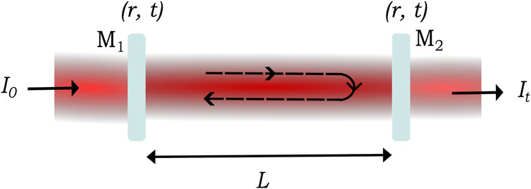
Figure 1. A plane parallel mirror (
The phase factor
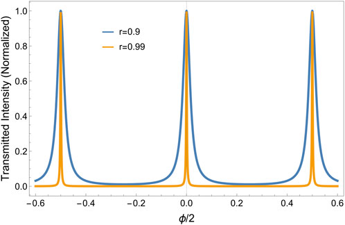
Figure 2. Transmitted intensity pattern showing the periodic occurrence of intensity maxima for resonant wavelengths (using Equation 2) for two different values of
Here
Another significant metric used to evaluate the quality of an optical cavity is finesse, defined as the ratio of FSR (Equation 3) to FWHM (Equation 4):
Equation 4 indicates that selecting mirrors with higher reflectivity leads to narrower transmission peaks. Conversely, Equation 5 shows that to observe very narrow linewidth peaks, one would need a cavity with very high finesse. We highlight the linewidth (FWHM) and finesse for different values of reflection coefficient
Equation 5 holds when the cavity is lossless. In a realistic cavity, the coefficients of reflection of both mirrors differ
In Equation 6, the factor
2.2 Cavity linewidth
The linewidth of a laser operating in a single transverse mode may be reduced (narrowed down) by stabilising it to the peak transmission of an ultra-high finesse cavity resonance. However, there is an ultimate lower limit on the laser linewidth that may be achieved in this manner. Since it is virtually impossible to distinguish spontaneously emitted photons from those emitted due to stimulated radiation, the phase of the laser light evolves randomly, putting a lower limit on the laser linewidth. Spontaneous emission introduces quantum noise due to the intrinsic random nature of the emission process itself, affecting the ultimate coherence and stability of laser light. These factors lead to the Schawlow-Townes linewidth, representing the fundamental limit to the linewidth of a laser (Hooker and Webb, 2010):
where
Just as the linewidth of the laser is constrained by phase noise, shot noise limits the precision with which we can measure its amplitude or intensity. At low powers, small intensity fluctuations in the laser become visible owing to the quantum nature of photons which imposes limits on the detection efficiency of the signal. The randomness is due to Poissonian statistics followed by photons and is limited by the quantum uncertainty principle (Yariv, 1989). Section 3.2 on the PDH method provides an example of evaluating shot noise.
2.3 Beam stability
Optical cavities exhibit two types of modes: longitudinal and transverse. While longitudinal modes depend on cavity length (quantified by the integer the
where
Usually the fundamental mode is made to couple to the cavity by designing it such that transverse modes lie quite far away from longitudinal resonances to avoid higher-order mode (HOM) degeneracy (Álvarez, 2019). HOMs become co-resonant with other fundamental modes when the ratio of longitudinal mode FSR to transverse mode FSR becomes an integer. Therefore, the ratio of
The survival of cavity modes is also influenced by mirror geometry, which can be planar, spherical, or a combination of both. Plano-concave mirrors are commonly preferred for easier alignment and better modal confinement. For stability, specific values of the radii of curvature (
The above equation is a set of hyperbolas dictating the allowed region for stable cavity configuration shown in Figure 3. Magnification in beam size after a round trip inside a cavity is provided by Equation 10:
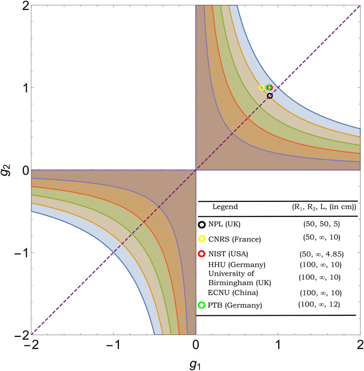
Figure 3. Stability diagram for an optical resonator. Circles show mirror configurations chosen by groups listed in Section 5. The purple-coloured dashed line across the plot shows the symmetric region where both mirror sizes have equal radii of curvatures. Notably, all groups have chosen to design their portable cavities near the edge of the stability region to achieve larger mode sizes at mirrors.
This indicates the need to design the cavity in the geometrical stability region to maintain a finite beam size. There are several cavity configurations listed below that fall under the stability region:
Mode size (beam transverse dimension) at the cavity mirror (subscripts stand for first and second mirror) is given by:
Where as the beam waist (minimum transverse dimension) inside cavity is given by:
Since laser beam intensity follows a Gaussian profile along the transverse direction, Equations 11, 12 become useful in evaluating radii of mirror curvatures and length of the cavity by measuring the mode size on a camera.
A larger spot (mode) size is desirable for a lower thermal noise floor (discussed in Section 4.1). From Figure 4A, we observe that larger mode sizes are achievable by arranging the cavity in a concentric configuration, which is in proximity to the edge of the stability diagram. For the plano-concave cavity (Figure 4B), the largest mode sizes at mirrors are achieved near
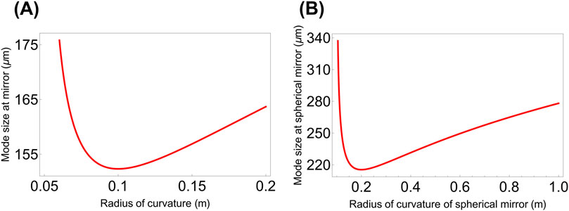
Figure 4. Plot of mode size (Equation 11) at mirror with variation in radii of curvature (A) for
3 Laser stabilization
Laser frequency stabilisation is an essential need in a plethora of applications, such as atomic clocks (Jiang et al., 2011), low-phase-noise microwave generation (Liu et al., 2024), gravitational wave detection (Meylahn et al., 2022), precision spectroscopy (Döringshoff et al., 2019), and other fields. The frequency stability of a diode laser deteriorates due to various noises arising out of mechanical vibrations, temperature fluctuations or noise from the laser current source. Such noise sources impact the stability of the laser frequency over different timescales. Slower or long-term drifts in laser frequency occur due to thermal effects over prolonged periods, ranging from a few hours or weeks to well over a few months. In contrast, faster or short-term fluctuations arising from technical noises affect the laser over much smaller time intervals, spanning from a microsecond to a few seconds (Boyd and Lahaye, 2024).
Various methods for laser frequency stabilization have been employed, utilizing cavity resonance or atomic transitions. The usual approach is to send a part of the unstabilized laser light towards a reference atomic transition or a cavity resonance and compare the output (and/or reflected) light with the remaining portion. One may choose a set point or reference point anywhere on the resulting atomic/cavity resonance lineshape. The set point can be selected either on the side of the transition/transmission lineshape (hence called side-of-fringe frequency stabilization) or at the top of the cavity/atomic resonance (top-of-fringe frequency stabilization), as depicted in Figure 5. An error signal, which is derived as a difference between the set point and actual frequency, is used to evaluate the laser frequency drift relative to the set point. It helps to provide feedback, which then corrects the laser frequency by modulating diode current or piezo voltage or a suitable combination of both using a control loop response (PID - Proportional, Integral and Derivative) system.
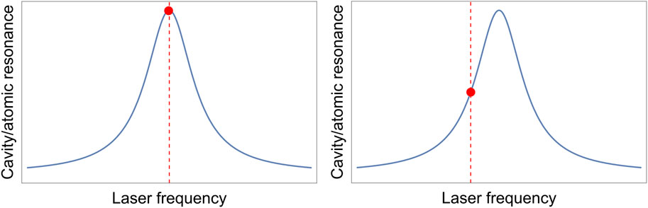
Figure 5. Laser frequency stabilization by choosing the set point at the top (left) or at the side (right) of the cavity transmission/reflection signal or atomic lineshape.
In the case of a side-of-fringe-based technique of laser frequency stabilization, the error signal becomes positive if the laser has drifted to a higher frequency and negative if it drifts to a lower frequency with respect to the set point identified on the transmission curve. While this error signal is just a constant offset, it has several practical disadvantages. The error signal amplitude is proportional to the drift in the actual laser frequency to the set point. Hence, it would be difficult to determine whether the changes in error signal amplitude stem from fluctuations in laser intensity or frequency. Consequently, any amplitude noise arising in the laser frequency can cause ambiguity in the error signal determination and impact the fidelity of stabilized laser frequency (Black, 2001). Moreover, due to the symmetry of cavity transmission or atomic lineshape profile, any significant frequency drift will result in overshooting of the corresponding set point position on the opposite side of the resonance. This leads to a negative error signal, compelling the feedback loop to adjust the frequency in the same direction, causing a runaway effect.
Alternatively, the top-of-fringe method can be used to set the reference point at the center of the cavity resonance peak. In this method, low-frequency modulation on the laser light is used to obtain the derivative of the cavity transmission signal, producing an asymmetric signal. Consequently, the sign of error signal varies with the laser frequency drift relative to the center point, effectively addressing the symmetry issue in the lineshape profile faced by the side-of-fringe laser stabilization method. However, environmental vibrations causing frequency drifts larger than the profile linewidth can quickly disengage the laser from the set point (Drever et al., 1983). Additionally, in the case of a cavity-based stabilization technique, any amplitude-modulated noise present in light, whose response is faster than the photon lifetime, cannot be detected through the cavity transmission signal. This limitation significantly affects the resolution of the laser stabilization mechanism.
(Hansch and Couillaud, 1980) proposed a simple yet elegant approach for laser frequency stabilization exploiting polarization of light. Their approach requires one to split a plane-polarized laser beam into two orthogonal polarizations by inserting a polarizer in the cavity axis. One polarization is reflected directly off the first mirror of the FP cavity, while the other passes through for a round trip, eventually returning to the first mirror. The error signal arises from the phase difference between these two polarizations. This method eliminates the need for external modulation, unlike the Pound-Drever-Hall (PDH) technique (discussed later). However, the error signal is a constant offset signal, making it susceptible to low-frequency laser technical noises.
(Bjorklund, 1980) introduced a laser frequency stabilization technique that references the laser to a Doppler-free saturated absorption line in a gas cell. In this method, the laser light is phase-modulated using an EOM, creating sidebands around the carrier frequency. When the phase-modulated laser interacts with the absorption line, it causes differential attenuation and phase shifts between the carrier and sidebands. A photodetector records the modulated light, and the signal is mixed with the original modulation frequency using a phase-sensitive detector, e.g., a lock-in amplifier, generating an error signal that indicates the deviation in laser frequency from the absorption line center. However, the effectiveness of this technique depends on the precision of the laser’s alignment to the absorption line center, as offsets can degrade the error signal quality. A significant limitation is RAM, which adds unwanted noises to the sidebands, increasing noise in the detected error signal and reducing frequency lock accuracy and stability.
(Shirley, 1982) introduced modulation transfer spectroscopy (MTS). In this method, near atomic resonance, an amplitude- or phase-modulated pump beam is made to coincide with an unmodulated counter-propagating beam, resulting in the transfer of modulation to the originally unmodulated beam. This process resembles a form of four-wave mixing. It creates a non-linear interaction near the absorption feature, generating a modulation sideband on the counter-propagating beam. The error signal used for laser stabilization is derived from this modulated absorption and dispersion line. Since MTS operates in a non-linear regime near resonance, it is less prone to background noise and baseline fluctuations that could shift the locking point of the laser. However, MTS has limitations due to the inherently weak signals generated through non-linear processes, requiring careful optimization to maximize the error signal slope for effective stabilization.
(Corwin et al., 1998) implemented the dichroic atomic vapor laser lock (DAVLL) method for laser stabilization. In this technique, a known magnetic field applied on the atomic vapor cell splits the Doppler-broadened absorption signal. The process involves converting the laser light to linearly polarized light, decomposing it into orthogonal circular polarizations (to probe the Zeeman split energy levels), and then detecting the absorption signals with balanced photodetectors. The error signal is generated based on the difference between the Doppler broadened absorption of two orthogonal circular polarizations. Since no external modulations are required, it is useful in the development of compact devices given the lower amount of resources (fewer optical and electronic components). However, DAVLL sensitivity is prone to shortcomings, such as small slope error signals and inaccurate frequency referencing points and is susceptible to environmental variations. The PDH technique provides a much larger slope in error signals, providing more precise frequency stabilization and avoiding the Doppler background issues present in DAVLL. Additionally, PDH is less affected by environmental factors, making it a more robust method of laser stabilization when frequency stabilization is required on the Hz or sub- Hz levels.
T.W. Hansch and J.L. Hall developed the optical frequency comb (OFC) technique, revolutionizing the precise measurement of optical frequencies. This groundbreaking achievement was recognized with the Nobel Prize in Physics in 2005 (Hänsch, 2006; Hall, 2006). To stabilize a laser using an OFC, the laser is referenced to one of the comb teeth. The evenly spaced frequency teeth are generated using mode-locked lasers. Frequency of the
Another recently developed approach to stabilize the laser frequency leverages spectral hole burning in rare-earth-ion-doped crystals (Wu et al., 2021; Julsgaard et al., 2007). At cryogenic temperatures, these crystals exhibit an exceptionally narrow and stable lineshape profile with extended coherence times, providing a reliable frequency reference (Cone et al., 2013; Thorpe et al., 2013). The laser is stabilized by referencing its frequency at the center of the hole-burning profile. The error signal generated here uses a method similar to the Pound-Drever-Hall (PDH) technique. The key difference is that the optical cavity is replaced by a spectral hole-burning lineshape in this method. This approach offers advantages such as compactness, vibration resistance, making the system suitable for miniaturization and portability. However, a key limitation is that the crystals require a low-temperature environment facilitated only through cryogenic systems, which pose significant challenges for field operations. Also, as a precursor to stabilize the laser through the hole-burning effect, it is essential to enable a pre-stabilisation of the target laser.
The PDH laser stabilization method addresses most of the aforementioned limitations by introducing fast phase modulation of laser light (modulating frequency much larger than the cavity’s linewidth). It results in sidebands on both sides of the laser frequency (carrier), providing a large capture range. Consequently, an error signal can be detected at high frequencies where most laser noises become weak, resulting in a high SNR ratio (Fox et al., 2003). The error signal is antisymmetric as it is a derivative of reflected light. Therefore, PDH method can be called a modified version of conventional cavity or atomic resonance-based top-of-fringe stabilization, using reflected light at higher modulation frequencies.
3.1 Pound-Drever-Hall (PDH) technique
A simple schematic for the Pound-Drever-Hall (PDH) method of laser frequency stabilization method is shown in Figure 6. The laser light is initially passed through a Faraday isolator, a key component designed to prevent any reflected light from other surfaces from disrupting the laser’s output. Next, the light goes through a polarizing beam splitter (PBS), which separates it into two parts. One part is sent to the experimental setup, while the other is directed towards the PDH setup. In the PDH setup, the light travels through an EOM, driven by a radio-frequency (RF) signal. This RF signal changes the refractive index of the medium, leading to phase modulation of the incoming light and generating a pair of sidebands on either side of the original laser frequency (the carrier). After the EOM, the light enters a high-finesse optical cavity via another PBS. When the light reflects off the high-finesse cavity, both the carrier and the sidebands are detected by a photodiode, which converts the optical signal into an electrical one containing phase information. This electrical signal is mixed with another RF signal at the modulation frequency, creating a beat signal. A low-pass filter removes the higher frequency components, isolating the DC portion, which contains information about the phase of the laser light. This phase information detects frequency deviations and is fed into a feedback loop to correct and stabilize the laser’s frequency.
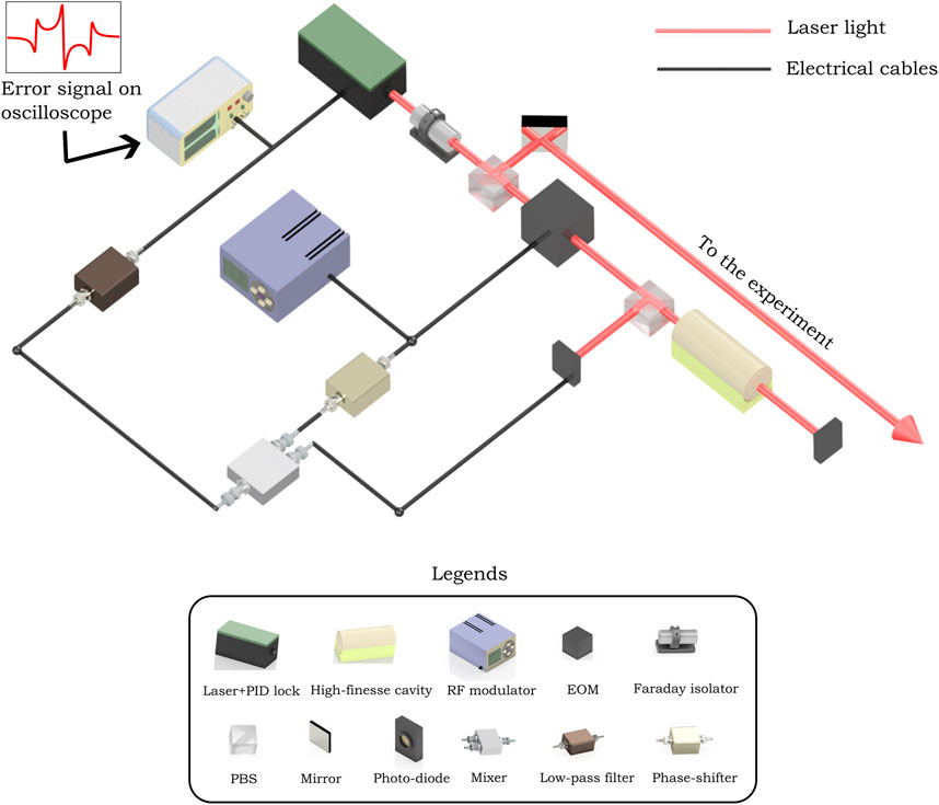
Figure 6. Schematic for PDH laser frequency stabilization method, which uses phase modulation of laser light. A polarizing beam splitter (PBS) is usually placed after a half-wave plate (not shown here) to control the intensity of light going along two polarizations.
Let us consider the laser’s electric field as
For sufficiently low modulation depth, only first-order terms can be retained, and the expression in Equation 13 reduces to
Under this approximation, almost all power is divided among three components. If the incident power on the EOM is
The above light signal containing sidebands impinges on the cavity, further breaking in reflected and transmitted parts. Following the argument given by (Black, 2001), two components make the total reflected light: one is the promptly reflected light, bouncing right away from the first mirror, and the other is the leakage light which enters the cavity and meets the promptly reflected light after making the round trip. The phase difference acquired by the leakage light decides the coherent sum of two parts. When the wavelength is near the resonance condition of the resonator, the total reflected light is given as:
Thus, the reflection amplitude
where
Due to the reflection of the carrier and the sidebands, each component (Equation 15) has its own reflection coefficients
The photodetector will read the reflected power:
or
Equation 18 or Equation 19 contains constant and oscillating terms (with frequencies
This expression is plotted for two different values of
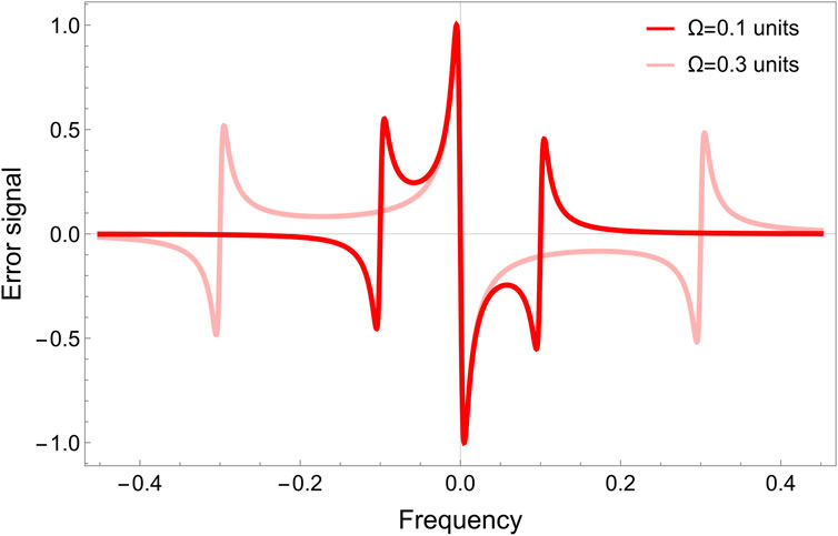
Figure 7. Plot of
3.1.1 Low modulation frequency regime
Here, we will examine the effect of very low modulation frequency, i.e.,
so that the phase term (Equation 20) can be written as:
and only the cosine terms survive in Equation 19. Then, the mixer will multiply the expression in Equation 22 with the RF signal (see Figure 6):
The signal in Equation 23 is passed through the low pass filter to yield the PDH error signal, which can be observed on an oscilloscope:
The importance of phase delay
The PDH error signal in Equation 25 is plotted in Figure 8. It demonstrates that the PDH error signal has a smaller acquisition range at lower modulation frequencies, thereby limiting its utility. Subsequent analysis will showcase that PDH serves best at higher modulation frequencies.
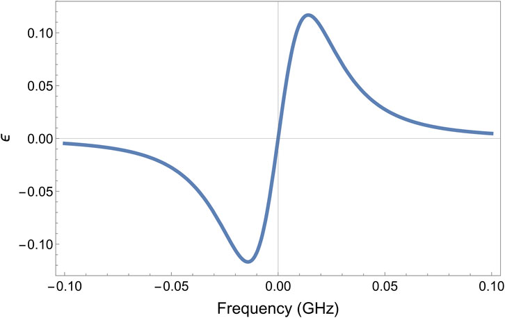
Figure 8. Error signal at very low modulation frequency. Parameters used are:
3.1.2 High modulation frequency regime
In the regime
This time, sine term survives in Equation 19, so that mixer multiplies the expression in Equation 26 with RF signal:
In this case, the expression in Equation 27 with yield a low pass signal (after adjusting phase
The expression in Equation 28 can be simplified using the following approximations to see the significance of high-frequency modulation. If the laser frequency drifts by a very small amount from the resonance
These small changes would be incorporated in the reflected carrier signal as:
Making use of
Then the PDH error signal for high modulation can be expressed as:
This error signal responds directly to any linear drift in the laser frequency
However, it is crucial to note that the PDH error signal is unable to distinguish between variations in laser frequency and changes in cavity length. This means that any change in the cavity length, while the laser output remains unchanged, will manifest as a shift in the laser’s frequency. This may happen because the cavity itself is influenced by various noise sources, as elaborated in the Section 4. Therefore, a more general expression for the error signal, containing both kinds of fluctuations, is given as:
3.1.3 Dependence of error signal on modulation depth
To achieve a substantial feedback signal, a considerably steeper error signal is required. Equation 29 suggests that
Solving Equation 31 yields the first zero at
Again, following the same procedure on Equation 32 to find the error signal, the useful expression after filtering out all AC terms reduces to:
where
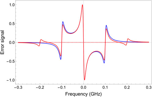
Figure 9. Effect of second order sidebands on the error signal. The blue curve is the error signal with first-order sidebands only (Equation 20), and the red curve contains both first and second-order sidebands (Equation 33). Ps1 and Ps2 are considered 1% and 33% of P0, respectively. Other parameters used: Ω = 100 MHz and FWHM = 10 MHz.
3.2 Shot noise limit
Laser stabilisation using the PDH technique is fundamentally restricted by the shot noise. Shot noise occurs because of the quantum nature of light (photon) itself. At very low laser powers, individual photons arrive randomly at the detector and produce larger fluctuations than the average signal. Black (2001) estimated shot noise in PDH error signal due to randomly approaching photons on the photodiode. On resonance, since there is no reflected carrier power, the detected power is approximate
Scaling this noise spectrum to yield equivalent noise sensitivity in the optical length of the cavity (dividing Equation 34 by proportional constant term
For a laser at
4 Noises limiting the stability of cavity
4.1 Fundamental thermal noise floor
The stability of an ultra-stable cavity is ultimately constrained due to fundamental thermal noise. It emanates due to the material properties of cavity components (mirror substrates, mirror coatings, and cavity spacer), leading to instability in the optical length of the cavity. Frequency of
In Equation 37
Equation 38 indicates that the stability in the cavity’s optical length governs the frequency stability of laser.
Levin formulated inherent thermal noise (Levin, 1998), based upon an earlier calculation reported for LIGO’s mirrors (González and Saulson, 1994) using fluctuation-dissipation theorem (Callen and Welton, 1951). Power spectral density due to thermal fluctuation noise at a particular frequency
Here,
Here,
Therefore, identifying suitable materials for mirror substrate, mirror coating, and spacer is crucial for reducing the fundamental thermal noise (Harry et al., 2012). Fused silica (FS), ultra-low-expansion (ULE) glass, zerodur, silicon, and some glass ceramics are popular choices for spacers and substrates because of their extremely low CTEs and lower loss angles. Table 1 lists some of the properties of these materials. At cryogenic temperature (
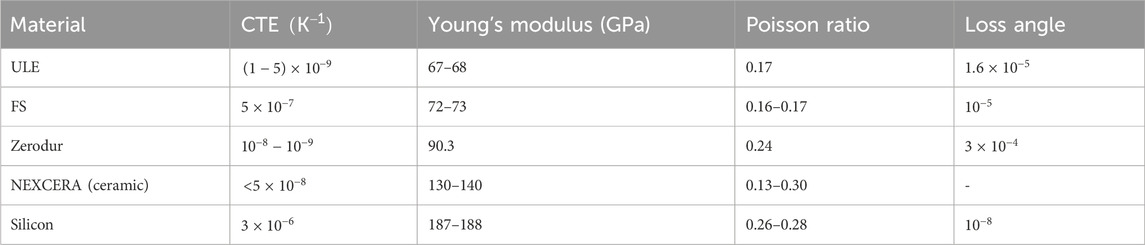
Table 1. Widely used materials for spacer and mirror substrate. CTEs are mentioned around room temperature.
Equation 39 can be further extended to describe the length fluctuations in the form of power spectral density due to all components of the cavity as:
where
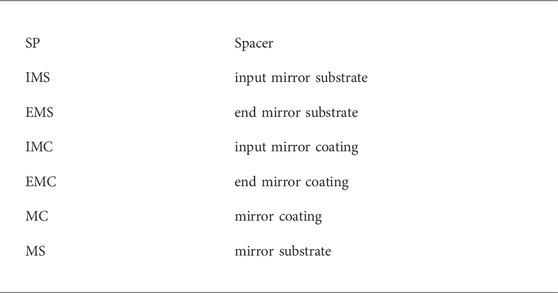
where the abbreviations used in Equations 41, 42 read as:
Kessler et al. (2012) built upon earlier put theoretical work on thermal noises and presented simplified formulas for quantifying substrate and coating contribution to noise:
It is important to note here that the mirrors were treated as infinite half-space in deriving these equations, that is, beam size was considered quite small relative to the mirror dimensions. Here,
where
The resulting fractional frequency
Generally, mirror coatings significantly contribute to fundamental thermal noise floor due to their higher loss angle (Amairi et al., 2013), while the noise due to the spacer has little effect on the overall fractional frequency instability.
From Equation 43, it is evident that the noise contribution due to mirror substrate and mirror coating scales as
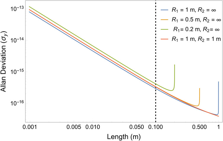
Figure 10. Variation in Allan deviation (thermal noise) with respect to cavity length for different combinations of mirror curvatures. For example, the near-planar geometry
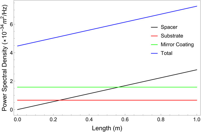
Figure 11. Plot of noise contribution from different parts of the optical cavity in the fundamental thermal noise floor with variation in length. Mirrors of fused silica and cavity spacer of ULE glass are considered here (see Equation 43; Equation 45).
4.2 External perturbations affecting the stability of cavity
4.2.1 Temperature fluctuation noise
Fluctuations in the ambient temperature cause cavity components to thermally expand (or compress), affecting the optical length along its axis. According to the law of thermal expansion, for a change of
Using the above equation and Equation 38, a change in laser frequency can be estimated arising out of temperature-induced changes in the cavity dimensions. To illustrate the severe impact of temperature fluctuations, let us consider the following example. For addressing the
If the temperature is stabilised at
As most materials used in optical cavities have a turn-around temperature, i.e., at which the first-order linear expansion coefficient vanishes, it is written more generally as:
where,
As highlighted in Section 4.1, additional complications arise when cavities are made from different materials for spacer and substrate. A mismatch in the CTE of the spacer and substrate tends to deform the cavity (by bending the mirrors) and hence change the effective optical length. The effective CTE in this case was given by (Notcutt et al., 1995):
where
Let us consider the widespread case of ULE glass and FS as spacer and substrate, respectively. Since
From an experimental perspective, temperature-induced drifts are minimized by housing the cavity inside a vacuum chamber while ensuring mechanical decoupling between them. This arrangement prevents ambient temperature changes from affecting the cavity surface’s local temperature. Multiple heat shields made of aluminium or titanium are used for this purpose. These shields are positioned between the cavity and vacuum chamber to efficiently block heat exchange due to convection and radiation, as illustrated in Figure 12A. The surfaces of heat shields are highly polished to reduce thermal radiation (a smooth surface ensures low emissivity), thereby significantly increasing the heat exchange time constant between the shields and cavity (Amairi, 2014). Radiative heat transfer can be minimized by actively controlling the temperature of the entire system, which can be accomplished through the use of active Peltier coolers and resistive heaters. This approach helps to suppress the temperature fluctuations and maintain the temperature around zero crossing of the spacer material (Figure 12B).
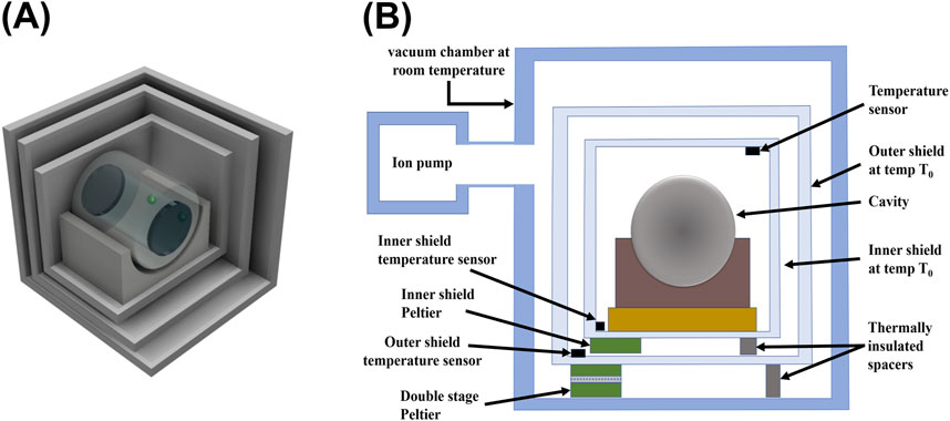
Figure 12. A general schematic diagram showing thermal isolation of cavity. (A) Multiple highly polished heat shields are placed around the cavity to reduce heat transfer between the cavity and the outer environment. (B) Cavity placed inside heat shields and vacuum chamber. Temperature is monitored using sensors placed at several locations and stabilised through Peltier coolers.
It is also worthwhile to note the cavity creep rate, which is a gradual long-term alteration in the dimension of the cavity. ULE material exhibits a creep rate of approximately one-tenth that of Zerodur. Moreover, ULE demonstrates adiabatic variation, whereas Zerodur experiences random step changes in length, proving ULE glass to be a better choice for cavity spacers (Roberts et al., 1999).
4.2.2 Vibrational noise
Low-frequency vibrational noises, spanning from 0.1 Hz to 100 Hz, such as seismic vibrations, pressure fluctuations in the atmosphere and other infrasonic acoustic noises, severely affect the stabilization of laser linewidth in sub-hertz level by exciting the vibrational eigenmodes of cavity (Nazarova et al., 2006). The extent to which these vibrations affect the cavity is influenced by its shape and the points at which it is mounted. Mounting the cavity vertically by fixing it at the midplane offers the advantage of ensuring that upper and lower halves undergo equal and opposite length changes, effectively nullifying the total effect and maintaining a constant length. Conversely, horizontal mounting configurations can also offer advantages, particularly because most vibrations are typically vertical, and Poisson’s ratio scales these vibrations down along the optical length. Additionally, various symmetrical configurations, such as cylindrical, cubic, spherical, and triangular shapes have been explored. However, the existence of complex material properties may lead to imperfections in symmetry. Therefore, finite element analysis (FEA) should be utilized to determine the most optimal mounting strategy and positions for the cavity (Banerjee et al., 2023). This approach aims to minimize sensitivity to mounting forces and external vibrations. Cylindrical and cubical designs are often preferred for their reduced volume and design simplicity. Notably, while a smaller cavity has a higher thermal noise floor, it simultaneously exhibits reduced susceptibility to external vibrational noise.
According to Hooke’s law, low acceleration force (such as self-weight due to gravity) can cause structural deformation of the cavity spacer. This is mainly attributed to two factors, the Poisson’s effect and mirror tilt (Álvarez, 2019). When subjected to a small acceleration
On the right-hand side of Equation 51, first term represents the relative change in length caused by minor external acceleration forces, with
For further reduction of fractional frequency instability, the entire cavity setup must be positioned on a passive or active vibration isolation (AVI) platform to sufficiently mitigate the vibrational noise and reach below the fundamental thermal noise. Although the air-suspended optical tables effectively attenuate vibrational noise above their resonance frequency (scaling as
4.2.3 Pressure fluctuations
Pressure fluctuations inside the cavity bore cause variations in the refractive index, thereby impacting the optical path length. The change in pressure occurs mainly due to temperature shifts and statistical fluctuations in the number of gas molecules present inside the cavity bore. However, frequency drift induced by pressure changes is less significant than that caused by the direct temperature fluctuations (Equation 47). The effect of change in pressure on the optical path length
which couples with the cavity length instability to yield Equation 53:
At room temperature,
4.2.4 Cavity power fluctuations
In high finesse optical cavities (Finesse
where
where
The power circulating within the cavity is significantly higher than the input power
(Keller et al., 2014) observed that a change of
4.3 Minimization of residual amplitude modulation (RAM)
EOMs used for phase modulation consist of birefringent crystals like lithium niobate
There is an additional photocurrent that contributes to the RAM noise due to thermal causes and other sources like the etalon effect (causes parasitic interference), misalignment of the crystal’s principal axis with the incident beam, inhomogeneity or defect in crystal, vibration instability, RF input signal fluctuation, non-uniformity of the modulating electric field, and photorefractive effect on the crystal (Domínguez et al., 2021) sets an offset to the PDH error signal (Herbers, 2021):
If the amplitude of the RAM remains constant, it only introduces a constant frequency offset denoted as
or
where,
and
In Equation 56–59,
Two primary approaches are utilized to minimize RAM noise. The first involves passive RAM noise reduction, achieved by tilting the parallel surfaces to eliminate parasitic interference resulting from the etalon effect. Additionally, carefully aligning the polarizing angles helps to reduce polarization noise. Active temperature stabilization of the EOM should also be implemented to prevent RAM generation resulting from fluctuations in natural birefringence and crystal deformation (Zhang et al., 2014). Moreover, during the selection of EOM crystals, it is better to consider crystals having low thermal dependence (Jin, 2021). Additionally, incorporating a special type of crystal before EOM to separate the e-ray and o-ray can help to reduce polarization noise (Figure 13).
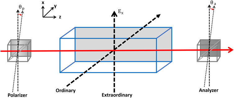
Figure 13. EOM crystal with ordinary and extraordinary axis where latter is aligned along the applied field direction. If the polarizer and analyzer axis are perfectly aligned with extraordinary axis,
RAM noise can be further suppressed by active control method, as illustrated in Figure 14. This method involves the use of two polarizing beam splitters to decrease the effective optical path length, thereby minimizing RAM. Additionally, spatial filtering is implemented using optical fibre. In the active control method, one part of light before the cavity is picked using a beam splitter and sent to a photodiode, whose signal is also modulated in the same way as the PDH signal. As a result, RAM, which is in phase with the PDH signal, can be detected, and a correction DC signal using bias tee can be applied to EOM. This additional DC signal can impact the phase difference between the e-ray and o-ray
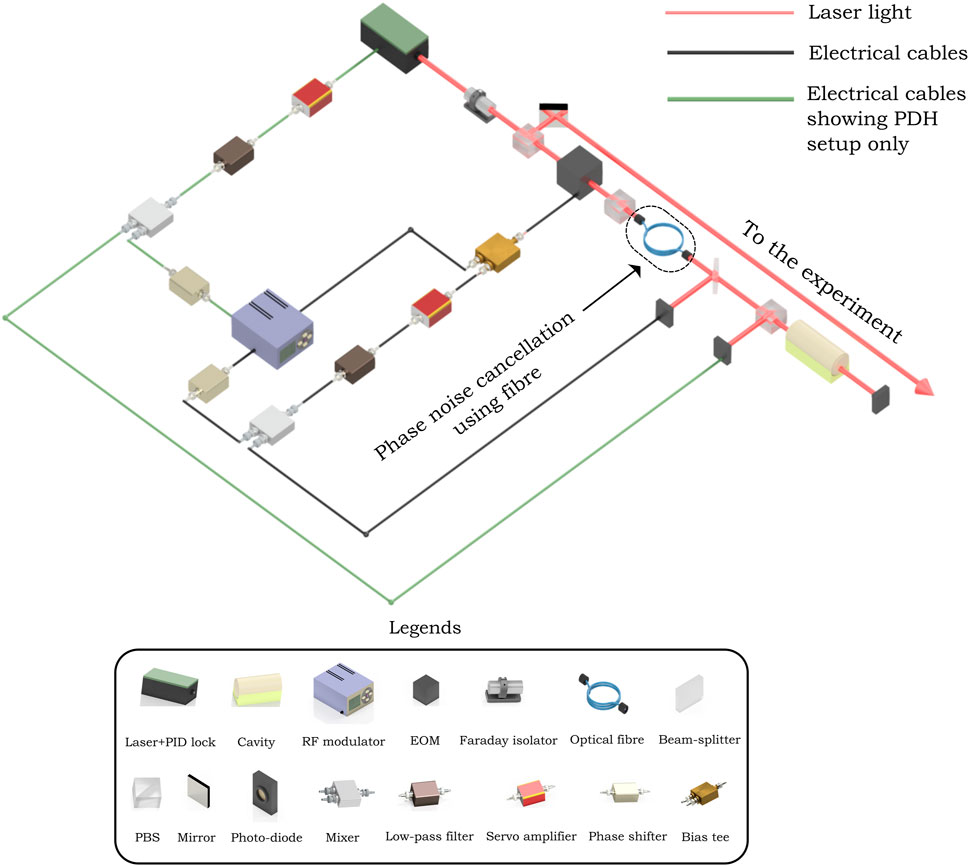
Figure 14. Schematic diagram of active stabilization of RAM noise. The PDH setup (Figure 6) is highlighted using green cables, which is surrounded by the RAM compensation setup. PBS is generally used with half-wave plates (not shown here) to distribute the intensity among two directions of polarization (except the PBS between EOM and fibre).
5 Case studies
Here, we mention a few noteworthy transportable cavities in detail. These designs emerged as paradigms due to their unique geometries, optimum mixed-material properties and mounting strategies. These optical cavities have made significant advancements in thermal and vibrational isolation, rendering them suitable for use in challenging environments like spacecraft, satellites, and terrestrial vehicles. They have also set a benchmark, inspiring research groups worldwide to confidently explore similar geometries. All of these cavities are made from ULE glass as the spacer material and FS as the mirror substrate material.
5.1 Cubical cavities
5.1.1 5
A cubic spacer of ULE (
NPL recently reported (Hill et al., 2021) a dual-optical axis cubic cavity based on a similar design for multiple laser stabilisation. This cavity had three bores drilled on parallel faces, and two of them were used as optical cavities with ULE rings attached on the backside of mirrors for thermal compensation. The cavity is mounted within a single aluminium thermal shield with highly polished walls, situated inside an aluminium vacuum chamber operated at less than
A recent collaboration between academia and various industries (Cole et al., 2024) lately published an article on a space-deployable cubic cavity at the technology readiness level (TRL) 6. Crystalline coating of
5.1.2 Dual-axis
A ULE glass cubic block of
5.2 Spherical cavity (NIST, United States)
A spherical cavity spacer (Leibrandt et al., 2011b) is designed for ultra-stable frequency control in outside laboratory environments by holding the spherical spacer at a “squeeze insensitive angle” (this angle refers to points on the spacer where changes in mounting force have little effect on cavity length). The authors also highlight the benefit of carving out multiple cavities in the sphere as long as mounting forces act on a diameter only. The spacer is
A significant improvement in the same cavity was published 2 years later, showcasing better acceleration sensitivity and thermal stabilisation by performing real-time feed-forward correction (Leibrandt et al., 2013). The cavity mounting scheme underwent significant changes, holding it by stainless steel flexure springs along a direction perpendicular to the optical axis in a cubic cage. Torlon balls are the contact between the spacer and springs and bear a load of
5.3 Cylindrical cavities
5.3.1
A cavity of length
5.3.2
This cavity was designed to be a subsystem for the cold Caesium atomic clock onboard a satellite to test Einstein’s Equivalence principle (Chen et al., 2014). A frequency comb will convert ultra-stable optical frequency at
5.3.3
(Świerad et al., 2016) proposed a space-grade laser system for the Strontium (Sr) optical lattice clock (SOC2) project by the European space agency (ESA). The clock transition (1S0-3P0) in the Sr atom has a frequency of
5.3.4
A field-deployable cylindrical cavity is made to sustain shocks up to
Two years later, the same group reported a new and improved transportable cavity system (Herbers et al., 2022) with the highest instability reported till date (
To conclude, we compare various parameters and features of transportable cavities covered in this section, summarised in the Table 2. Identifying force-insensitive geometry and mounting strategies is the first step in designing a cavity. A symmetric cavity (cubical, spherical and cylindrical) can readily distribute the load evenly throughout the body. At the same time, mounting methodology recognizes the points where the effect of compressive forces is minimal on the cavity. Consequently, the cavities in Section 5.1.1 and Section 5.2 offer more ruggedness towards vibrational noise and hence show a lower Allan deviation noise limit. Thereafter, it comes down to selecting the suitable material for the cavity, where all groups have chosen similar materials for the spacer and substrate. ULE glass has more resistance to thermal expansion while FS have a smaller loss angle, which makes a good pair in terms of thermal stability and lower fundamental noise floor. However, a difference in the CTE null temperature of constituting materials leads to a decrease in the combined CTE null, which is favourable in some of the cases, as it falls in a range near room temperature. The development of crystalline mirror coatings has significantly improved the thermal noise limit, as in cases given in Section 5.1.1 and Section 5.3.4. Noise contribution due to mirror coatings is still the biggest hurdle to improving the fundamental Allan deviation limit, and researchers are doing intensive studies to find alternatives. Further, acceleration sensitivity is a direct measure of the robustness of transportable systems under external vibrations. As rigid mounting is necessary to secure the cavity under rugged operations outside lab environments, the above-listed groups have shown profound progress in mounting strategies to decouple vibrational noise. Thermal fluctuations caused by any small variations in the cavity environment are minimized by multiple well-polished heat shields coated with low-emissivity materials. However, system weight should be controlled for transportability purposes by carefully choosing the housing materials. Vacuum levels of
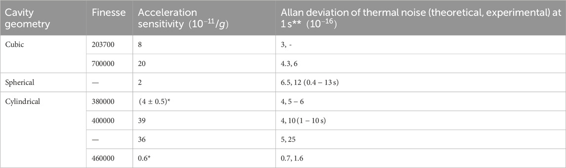
Table 2. Comparison among the various cavities mentioned here. Acceleration sensitivity is reported for the worst cases (highest value along one of the orientations). *These values are originally reported in unit of
6 Summary and outlook
This article is dedicated to developing and understanding transportable high-finesse, ultra-stable optical cavities, which have emerged as critical tools to stabilize frequencies for portable optical clocks, enable out-of-lab high-precision experiments and generation of highly stable microwave signals, etc. The article begins with discussions on geometrical considerations for a high-finesse, ultra-stable optical cavity and highlights that high-quality mirrors with reflection coefficient
Furthermore, this article also discusses different sources of external noise, such as vibrations, temperature fluctuations, acoustic noise, pressure fluctuations inside the cavity, and input beam power fluctuations that can compromise the laser frequency stability, and reviews strategies to mitigate them. To diminish the effect of deformation in length due to self-weight and mirror tilt in portable cavities, rigidly mounting the cavity on its Airy points effectively minimizes the effects of compressive forces on optical length which also helps in achieving acceleration sensitivity at
We have also discussed a few significant case studies reported by various research groups over the past 15 years. Figure 15 shows a growing interest in transportable optical cavities in recent years worldwide. These case studies offer guidance and advice to anyone aiming to design and develop such transportable optical cavity systems. This review offers critical insight and encourages meticulous considerations in material selection and notes the importance of prior simulations to overcome various noises and possible deformations. With all the parameters studied well and controlled carefully, it is feasible to construct portable cavities at stability levels compared to stationary cavities in laboratories. Future developments are eagerly awaited for coating materials to surpass the fundamental thermal noise limit beyond
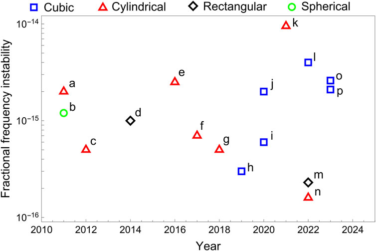
Figure 15. Progress of various terrestrial and space-borne (transportable) cavities over the past 15 years. Source of data: (A) (Vogt et al., 2011), (B) (Leibrandt et al., 2011b), (C) (Argence et al., 2012), (D) (Chen et al., 2014), (E) (Świerad et al., 2016), (F) (Tai et al., 2017), (G) (Tao and Chen, 2018), (H) (Sanjuan et al., 2019), (I) (Chen et al., 2020), (J) (Wang et al., 2020) (K) (Xu et al., 2021), (L) (Stacey et al., 2023), (M) (Xiao et al., 2022), (N) (Herbers et al., 2022), (O) (Jiao et al., 2023), (P) (Zhao et al., 2023).
Author contributions
RP: Writing–original draft, Writing–review and editing. VY: Writing–original draft, Writing–review and editing. AS: Conceptualization, Funding acquisition, Project administration, Resources, Supervision, Validation, Visualization, Writing–review and editing.
Funding
The author(s) declare that financial support was received for the research, authorship, and/or publication of this article. RP gratefully acknowledges financial support from the University Grants Commission (UGC) through the Junior Research Fellowship (JRF) (NTA Ref. No.: 231610201995). VY expresses gratitude for the financial support he received from the Prime Minister’s Research Fellowship (PMRF). AS acknowledges funding received from IIT Tirupati Navavishkar I-Hub Foundation (iNiF) through the grant number PHY2324010NHUBARIJ.
Acknowledgments
We thank Ashok Chilukoti and Sumit Achar for meticulously reviewing the manuscript. We acknowledge Gyanendra Pratap Roy and Poorvisha C for their valuable assistance with figures and 3D diagrams. We sincerely thank Sumit Achar, Abhijit Kundu and Himanshu Miriyala for sharing their insightful suggestions while preparing the manuscript.
Conflict of interest
The authors declare that the research was conducted in the absence of any commercial or financial relationships that could be construed as a potential conflict of interest.
Publisher’s note
All claims expressed in this article are solely those of the authors and do not necessarily represent those of their affiliated organizations, or those of the publisher, the editors and the reviewers. Any product that may be evaluated in this article, or claim that may be made by its manufacturer, is not guaranteed or endorsed by the publisher.
Footnotes
1Gravity Recovery and Climate Experiment Follow-on or GRACE-FO, in short, is a successor mission of GRACE (which was operational between 2002-2017). It is a joint mission between NASA, United States and GFZ, Germany, launched in 2018.
2Next-Generation Gravity Mission (NGGM) is a proposed space mission between European Space Agency (ESA) and NASA, United States.
3Space-Time Asymmetry Research (STAR) is a proposed future mission by NASA, United States, involving people from Germany, Britain, and Saudi Arabia. It aims to study special and general relativity with better precision.
4BOOST (BOOst Symmetry Test) is a proposed space mission by DLR, Germany, to study Lorentz invariance violations.
5Space–Time Explorer and Quantum Equivalence Space Test (STE-QUEST) was a proposed mission not selected for ESA’s cosmic vision M3, but it is noteworthy to mention because it proposed optical atomic clocks will be deployed in space to test Einstein’s equivalence principle.
6Space Optical Clocks (SOC) is ESA’s planned mission to place optical clocks and frequency comb on the International Space Station (ISS) for improving the microwave link between Earth and ISS.
7https://llis.nasa.gov/lesson/824
References
Abdel-Hafiz, M., Ablewski, P., Al-Masoudi, A., Martínez, H., Balling, P., Barwood, G., et al. (2019). Guidelines for developing optical clocks with fractional frequency uncertainty. Tech. Rep. Leibniz Univ. Hann. Ger. doi:10.15488/5553
Alnis, J., Matveev, A., Wilken, T., Kolachevsky, N., Udem, T., and Hänsch, T. (2008). Subhertz linewidth diode lasers by stabilization to vibrationally and thermally compensated ultralow-expansion glass Fabry-Pérot cavities. Phys. Rev. A 77, 053809. doi:10.1103/PhysRevA.77.053809
Altschul, B., Bailey, Q., Blanchet, L., Bongs, K., Bouyer, P., Cacciapuoti, L., et al. (2015). Quantum tests of the Einstein equivalence principle with the STE–QUEST space mission. Adv. Space Res. 55, 501–524. doi:10.1016/j.asr.2014.07.014
Álvarez, M. (2019). Optical cavities for optical atomic clocks, atom interferometry and gravitational-wave detection. (UK): School of Physics and Astronomy, University of Birmingham. Ph.D. thesis. doi:10.1007/978-3-030-20863-9
Amairi, S. (2014). A long optical cavity for sub-Hertz laser spectroscopy. Gottfried Wilhelm Leibniz Universität Hannover. Ph.D. thesis.
Amairi, S., Legero, T., Kessler, T., Sterr, U., Wübbena, J., Mandel, O., et al. (2013). Reducing the effect of thermal noise in optical cavities. Appl. Phys. B 113, 233–242. doi:10.1007/s00340-013-5464-8
Argence, B., Prevost, E., Lévèque, T., Goff, R., Bize, S., Lemonde, P., et al. (2012). Prototype of an ultra-stable optical cavity for space applications. Opt. Express 20, 25409–25420. doi:10.1364/OE.20.025409
Banerjee, S., Johnson, S., Vaghasia, Y., Palodhi, K., Haldar, S., and De, S. (2023). Modelling and design of ultra-high stable Fabry–Pérot cavity. Int. J. Mech. Sci. 250, 108299. doi:10.1016/j.ijmecsci.2023.108299
Bergquist, J., Itano, W., and Wineland, D. (1992). Laser stabilization to a single ion. Front. Laser Spectrosc. Proc. Int. Sch. Phys. “Enrico Fermi 120, 359–376.
Bjorklund, G. (1980). Frequency-modulation spectroscopy: a new method for measuring weak absorptions and dispersions. Opt. Lett. 5, 15–17. doi:10.1364/OL.5.000015
Black, E. (2001). An introduction to Pound–Drever–Hall laser frequency stabilization. Am. J. Phys. 69, 79–87. doi:10.1119/1.1286663
Boldbaatar, E., Grant, D., Choy, S., Zaminpardaz, S., and Holden, L. (2023). Evaluating optical clock performance for GNSS positioning. Sensors 23, 5998. doi:10.3390/s23135998
Bondarescu, M., Kogan, O., and Chen, Y. (2008). Optimal light beams and mirror shapes for future LIGO interferometers. Phys. Rev. D. 78, 082002. doi:10.1103/PhysRevD.78.082002
Bondarescu, R., Schärer, A., Lundgren, A., Hetényi, G., Houlié, N., Jetzer, P., et al. (2015). Ground-based optical atomic clocks as a tool to monitor vertical surface motion. Geophys. J. Int. 202, 1770–1774. doi:10.1093/gji/ggv246
Bongs, K., Singh, Y., Smith, L., He, W., Kock, O., Świerad, D., et al. (2015). Development of a strontium optical lattice clock for the SOC mission on the ISS. Proc. Phys. 16, 553–564. doi:10.1016/j.crhy.2015.03.009
Bothwell, T., Kedar, D., Oelker, E., Robinson, J., Bromley, S., Tew, W., et al. (2019). JILA SrI optical lattice clock with uncertainty of 2.0 × 10⁻¹⁸. Metrologia 56, 065004. doi:10.1088/1681-7575/ab4089
Boyd, J., and Lahaye, T. (2024). A basic introduction to ultrastable optical cavities for laser stabilization. Am. J. Phys. 92, 50–58. doi:10.1119/5.0161369
Braxmaier, C., Schuldt, T., Allab, M., van Zoest, T., Theil, S., Pelivan, I., et al. (2010). “The space-time asymmetry research (STAR) program,” in Eftf, 1–8. doi:10.1109/EFTF.2010.6533664
Callen, H., and Welton, T. (1951). Irreversibility and generalized noise. Phys. Rev. 83, 34–40. doi:10.1103/PhysRev.83.34
Chalermsongsak, T., Hall, E., Cole, G., Follman, D., Seifert, F., Arai, K., et al. (2016). Coherent cancellation of photothermal noise in GaAs/Al0.92Ga0.08 Bragg mirrors. Metrologia 53, 860–868. doi:10.1088/0026-1394/53/2/860
Chen, L., Hall, J., Ye, J., Yang, T., Zang, E., and Li, T. (2006). Vibration-induced elastic deformation of Fabry-Pérot cavities. Phys. Rev. A 74, 053801. doi:10.1103/PhysRevA.74.053801
Chen, Q., Nevsky, A., Cardace, M., Schiller, S., Legero, T., Häfner, S., et al. (2014). A compact, robust, and transportable ultra-stable laser with a fractional frequency instability of 1 × 10⁻¹⁵. Rev. Sci. Instrum. 85, 113107. doi:10.1063/1.4898334
Chen, X., Jiang, Y., Li, B., Yu, H., Jiang, H., Wang, T., et al. (2020). Laser frequency instability of 6 × 10⁻¹⁶ using 10-cm-long cavities on a cubic spacer. Chin. Opt. Lett. 18, 030201. doi:10.3788/col202018.030201
Cole, G., Koller, S., Greve, C., Barwood, G., Deutsch, C., Gaynor, P., et al. (2024). Towards space-deployable laser stabilization systems based on vibration-insensitive cubic cavities with crystalline coatings. Opt. Express 32, 5380–5396. doi:10.1364/OE.506833
Cole, G., Zhang, W., Martin, M., Ye, J., and Aspelmeyer, M. (2013). Tenfold reduction of Brownian noise in high-reflectivity optical coatings. Nat. Photonics 7, 644–650. doi:10.1038/nphoton.2013.174
Cone, R., Thiel, C., Sun, Y., Böttger, T., and Macfarlane, R. (2013). “Quantum information, laser frequency stabilization, and optical signal processing with rare-earth doped materials,” in Frontiers in optics 2013 (Washington, DC: Optica Publishing Group). LTu1G.3. doi:10.1364/LS.2013.LTu1G.3
Corwin, K., Lu, Z.-T., Hand, C., Epstein, R., and Wieman, C. (1998). Frequency-stabilized diode laser with the zeeman shift in an atomic vapor. Appl. Opt. 37, 3295–3298. doi:10.1364/AO.37.003295
Dai, X., Jiang, Y., Hang, C., Bi, Z., and Ma, L. (2015). Thermal analysis of optical reference cavities for low sensitivity to environmental temperature fluctuations. Opt. Express 23, 5134–5146. doi:10.1364/OE.23.005134
DeMille, D., Doyle, J., and Sushkov, A. (2017). Probing the frontiers of particle physics with tabletop-scale experiments. Science 357, 990–994. doi:10.1126/science.aal3003
Derevianko, A., Gibble, K., Hollberg, L., Newbury, N., Oates, C., Safronova, M., et al. (2022). Fundamental physics with a state-of-the-art optical clock in space. Quantum Sci. Technol. 7, 044002. doi:10.1088/2058-9565/ac7df9
Domínguez, A., Larcher, W., and Kozameh, C. (2021). Fundamental residual amplitude modulation in electro-optic modulators. arXiv. doi:10.48550/arXiv.1710.10719
Döringshoff, K., Gutsch, F., Schkolnik, V., Kürbis, C., Oswald, M., Pröbster, B., et al. (2019). Iodine frequency reference on a sounding rocket. Phys. Rev. Appl. 11, 054068. doi:10.1103/PhysRevApplied.11.054068
Drever, R., Hall, J., Kowalski, F., Hough, J., Ford, G., Munley, A., et al. (1983). Laser phase and frequency stabilization using an optical resonator. Appl. Phys. B 31, 97–105. doi:10.1007/BF00702605
Fox, R. (2009). Temperature analysis of low-expansion Fabry-Pérot cavities. Opt. Express 17, 15023–15031. doi:10.1364/OE.17.015023
Fox, R., Oates, C., and Hollberg, L. (2003). 1. Stabilizing diode lasers to high-finesse cavities. Cavity-Enhanced Spectrosc. 40, 1–46. doi:10.1016/S1079-4042(03)80017-6
Gill, P. (2005). Optical frequency standards. Metrologia 42, S125–S137. doi:10.1088/0026-1394/42/3/S13
Gill, P., Margolis, H., Curtis, A., Klein, H., Lea, S., Webster, S., et al. (2008). “Optical atomic clocks for space,” in Tech. rep. Teddington (UK): National Physical Laboratory.
González, G., and Saulson, P. (1994). Brownian motion of a mass suspended by an anelastic wire. J. Acoust. Soc. Am. 96, 207–212. doi:10.1121/1.410467
Grotti, J., Koller, S., Vogt, S., Häfner, S., Sterr, U., Lisdat, C., et al. (2018). Geodesy and metrology with a transportable optical clock. Nat. Phys. 14, 437–441. doi:10.1038/s41567-017-0042-3
Häfner, S., Falke, S., Grebing, C., Vogt, S., Legero, T., Merimaa, M., et al. (2015). 8 × 10⁻¹⁷ fractional laser frequency instability with a long room-temperature cavity. Opt. Lett. 40, 2112–2115. doi:10.1364/OL.40.002112
Häfner, S., Herbers, S., Vogt, S., Lisdat, C., and Sterr, U. (2020). Transportable interrogation laser system with an instability of mod 3 × 10⁻¹⁶. Opt. Express 28, 16407–16416. doi:10.1364/OE.390105
Hall, J. (2006). Nobel lecture: defining and measuring optical frequencies. Rev. Mod. Phys. 78, 1279–1295. doi:10.1103/RevModPhys.78.1279
Hänsch, T. (2006). Nobel lecture: passion for precision. Rev. Mod. Phys. 78, 1297–1309. doi:10.1103/RevModPhys.78.1297
Hansch, T., and Couillaud, B. (1980). Laser frequency stabilization by polarization spectroscopy of a reflecting reference cavity. Opt. Commun. 35, 441–444. doi:10.1016/0030-4018(80)90069-3
G. Harry, T. Bodiya, and R. DeSalvo (2012). Optical coatings and thermal noise in precision measurement (Cambridge University Press).
He, K., Li, Q., Liu, L., and Yang, H. (2021). Active vibration isolation of ultra-stable optical reference cavity of space optical clock. Aerosp. Sci. Technol. 112, 106633. doi:10.1016/j.ast.2021.106633
Herbers, S. (2021). Transportable ultra-stable laser system with an instability down to 10−16. Gottfried Wilhelm Leibniz Univ. Hann. Ger. Ph.D. thesis. doi:10.15488/11624
Herbers, S., Häfner, S., Dörscher, S., Lücke, T., Sterr, U., and Lisdat, C. (2022). Transportable clock laser system with an instability of 10−16. Opt. Lett. 47, 5441–5444. doi:10.1364/OL.470984
Hill, I., Hendricks, R., Donnellan, S., Gaynor, P., Allen, B., Barwood, G., et al. (2021). Dual-axis cubic cavity for drift-compensated multi-wavelength laser stabilisation. Opt. Express 29, 36758–36768. doi:10.1364/OE.436019
Hollberg, L. (2020). “Atomic clocks for GNSS,”, 47. John Wiley and Sons, Ltd, 1497–1519. doi:10.1002/9781119458555.ch47
Itano, W., Bergquist, J., Bollinger, J., Gilligan, J., Heinzen, D., Moore, F., et al. (1993). Quantum projection noise: population fluctuations in two-level systems. Phys. Rev. A 47, 3554–3570. doi:10.1103/PhysRevA.47.3554
Jiang, Y., Ludlow, A., Lemke, N., Fox, R., Sherman, J., Ma, L., et al. (2011). Making optical atomic clocks more stable with 10−16-level laser stabilization. Nat. Photonics 5, 158–161. doi:10.1038/nphoton.2010.313
Jiao, D., Deng, X., Gao, J., Zhang, L., Xu, G., Liu, T., et al. (2023). Highly vibration-resistant sub-hertz ultra-stable laser passing over 1700 km transport test. Infrared Phys. Technol. 130, 104608. doi:10.1016/j.infrared.2023.104608
Jin, L. (2021). Suppression of residual amplitude modulation of ADP electro-optical modulator in Pound-Drever-Hall laser frequency stabilization. Opt. Laser. Technol. 136, 106758. doi:10.1016/j.optlastec.2020.106758
Julsgaard, B., Walther, A., Kröll, S., and Rippe, L. (2007). Understanding laser stabilization using spectral hole burning. Opt. Express 15, 11444–11465. doi:10.1364/OE.15.011444
Keller, J., Ignatovich, S., Webster, S., and Mehlstäubler, T. (2014). Simple vibration-insensitive cavity for laser stabilization at the 10−16 level. Appl. Phys. B 116, 203–210. doi:10.1007/s00340-013-5676-y
Kessler, T., Legero, T., and Sterr, U. (2012). Thermal noise in optical cavities revisited. J. Opt. Soc. Am. B 29, 178–184. doi:10.1364/JOSAB.29.000178
Landerer, F., Flechtner, F., Save, H., Webb, F., Bandikova, T., Bertiger, W., et al. (2020). Extending the global mass change data record: GRACE follow-on instrument and science data performance. Geophys. Res. Lett. 47, e2020GL088306. doi:10.1029/2020GL088306
Legero, T., Kessler, T., and Sterr, U. (2010). Tuning the thermal expansion properties of optical reference cavities with Fused Silica mirrors. J. Opt. Soc. Am. B 27, 914–919. doi:10.1364/JOSAB.27.000914
Leibrandt, D., Bergquist, J., and Rosenband, T. (2013). Cavity-stabilized laser with acceleration sensitivity below 10−12 g−1. Phys. Rev. A 87, 023829. doi:10.1103/PhysRevA.87.023829
Leibrandt, D., Thorpe, M., Bergquist, J., and Rosenband, T. (2011a). Field-test of a robust, portable, frequency-stable laser. Opt. Express 19, 10278–10286. doi:10.1364/OE.19.010278
Leibrandt, D., Thorpe, M., Notcutt, M., Drullinger, R., Rosenband, T., and Bergquist, J. (2011b). Spherical reference cavities for frequency stabilization of lasers in non-laboratory environments. Opt. Express 19, 3471–3482. doi:10.1364/OE.19.003471
Levin, Y. (1998). Internal thermal noise in the ligo test masses: a direct approach. Phys. Rev. D. 57, 659–663. doi:10.1103/PhysRevD.57.659
Liu, Y., Lee, D., Nakamura, T., Jin, N., Cheng, H., Kelleher, M., et al. (2024). Low-noise microwave generation with an air-gap optical reference cavity. Apl. Photonics 9, 010806. doi:10.1063/5.0174544
Ludlow, A., Boyd, M., Ye, J., Peik, E., and Schmidt, P. (2015). Optical atomic clocks. Rev. Mod. Phys. 87, 637–701. doi:10.1103/RevModPhys.87.637
Margolis, H. (2009). Frequency metrology and clocks. J. Phys. B At. Mol. Opt. Phys. 42, 154017. doi:10.1088/0953-4075/42/15/154017
Marlow, B., and Scherer, D. (2021). A review of commercial and emerging atomic frequency standards. IEEE Trans. Ultrason. Ferroelectr. Freq. Control 68, 2007–2022. doi:10.1109/TUFFC.2021.3049713
Mehlstäubler, T., Grosche, G., Lisdat, C., Schmidt, P., and Denker, H. (2018). Atomic clocks for geodesy. Rep. Prog. Phys. 81, 064401. doi:10.1088/1361-6633/aab409
Meylahn, F., Knust, N., and Willke, B. (2022). Stabilized laser system at 1550 nm wavelength for future gravitational-wave detectors. Phys. Rev. D. 105, 122004. doi:10.1103/PhysRevD.105.122004
Millo, J., Magalhães, D., Mandache, C., Le Coq, Y., English, E., Westergaard, P., et al. (2009). Ultrastable lasers based on vibration insensitive cavities. Phys. Rev. A 79, 053829. doi:10.1103/PhysRevA.79.053829
Milonni, P., and Eberly, J. (2010). Laser oscillation: power and frequency. John Wiley and Sons, Ltd, 175–228. chap. 5.
Nazarova, T., Riehle, F., and Sterr, U. (2006). Vibration-insensitive reference cavity for an ultra-narrow-linewidth laser. Appl. Phys. B 83, 531–536. doi:10.1007/s00340-006-2225-y
Nicklaus, K., Herding, M., Wang, X., Beller, N., Fitzau, O., Giesberts, M., et al. (2017). “High stability laser for next generation gravity missions,” in Proc. SPIE. Editors Z. Sodnik, B. Cugny, and N. Karafolas Bellingham, WA: International Society for Optics and Photonics SPIE, 10563. doi:10.1117/12.2304161
Notcutt, M., Taylor, C., Mann, A., and Blair, D. (1995). Temperature compensation for cryogenic cavity stabilized lasers. J. Phys. D. Appl. Phys. 28, 1807–1810. doi:10.1088/0022-3727/28/9/008
Numata, K., Kemery, A., and Camp, J. (2004). Thermal-noise limit in the frequency stabilization of lasers with rigid cavities. Phys. Rev. Lett. 93, 250602. doi:10.1103/PhysRevLett.93.250602
Riehle, F. (2015). Towards a redefinition of the second based on optical atomic clocks. C. R. Phys. 16, 506–515. doi:10.1016/j.crhy.2015.03.012
Roberts, M., Taylor, P., and Gill, P. (1999). Laser linewidth at the sub-Hertz level. Tech. Rep. Available at: https://eprintspublications.npl.co.uk/1250/
Rodrigues, W., and Oliveira, E. (2016). The many faces of maxwell, Dirac and Einstein equations. 2 edn. Cham: Springer.
Roslund, J., Cingöz, A., Lunden, W., Partridge, G., Kowligy, A., Roller, F., et al. (2024). Optical clocks at sea. Nature 628, 736–740. doi:10.1038/s41586-024-07225-2
Safronova, M., Budker, D., DeMille, D., Kimball, D., Derevianko, A., and Clark, C. (2018). Search for new Physics with atoms and molecules. Rev. Mod. Phys. 90, 025008. doi:10.1103/RevModPhys.90.025008
Sanjuan, J., Abich, K., Gohlke, M., Resch, A., Schuldt, T., Wegehaupt, T., et al. (2019). Long-term stable optical cavity for special relativity tests in space. Opt. Express 27, 36206–36220. doi:10.1364/OE.27.036206
Schwarz, R., Dörscher, S., Al-Masoudi, A., Benkler, E., Legero, T., Sterr, U., et al. (2020). Long term measurement of the 87Sr clock frequency at the limit of primary Cs clocks. Phys. Rev. Res. 2, 033242. doi:10.1103/PhysRevResearch.2.033242
Shirley, J. (1982). Modulation transfer processes in optical heterodyne saturation spectroscopy. Opt. Lett. 7, 537–539. doi:10.1364/OL.7.000537
Siegman, A. (1986). Lasers. Melville, NY: University Science Books. Available at: https://uscibooks.aip.org/books/lasers/
Stacey, J., Barwood, G., Spampinato, A., Tsoulos, P., Robinson, C., Gaynor, P., et al. (2023). “Laser frequency stabilisation for the LISA mission using a cubic cavity,” in Proc. SPIE. Editors K. Minoglou, N. Karafolas, and B. Cugny, 12777. doi:10.1117/12.2691441266
Swallows, M., Martin, M., Bishof, M., Benko, C., Lin, Y., Blatt, S., et al. (2012). Operating a 87 Sr optical lattice clock with high precision and at high density. IEEE Trans. Ultrason. Ferroelectr. Freq. Control 59, 416–425. doi:10.1109/TUFFC.2012.2210
Świerad, D., Häfner, S., Vogt, S., Venon, B., Holleville, D., Bize, S., et al. (2016). Ultra-stable clock laser system development towards space applications. Sci. Rep. 6, 33973. doi:10.1038/srep33973
Tai, Z.-Y., Yan, L.-L., Zhang, Y.-Y., Zhang, X.-F., Guo, W.-G., Zhang, S.-G., et al. (2017). Transportable 1555-nm ultra-stable laser with sub-0.185-Hz linewidth. Chin. Phys. Lett. 34, 090602. doi:10.1088/0256-307X/34/9/090602
Takamoto, M., Ushijima, I., Ohmae, N., Yahagi, T., Kokado, K., Shinkai, H., et al. (2020). Test of general relativity by a pair of transportable optical lattice clocks. Nat. Photonics 14, 411–415. doi:10.1038/s41566-020-0619-8
Tao, B.-K., and Chen, Q.-F. (2018). A vibration-insensitive-cavity design holds impact of higher than $$100g$$ 100 g. Appl. Phys. B 124, 228. doi:10.1007/s00340-018-7096-5
Tapley, B., Watkins, M., Flechtner, F., Reigber, C., Bettadpur, S., Rodell, M., et al. (2019). Contributions of GRACE to understanding climate change. Nat. Clim. Change 9, 358–369. doi:10.1038/s41558-019-0456-2
Thorpe, M., Leibrandt, D., and Rosenband, T. (2013). Shifts of optical frequency references based on spectral-hole burning in Eu3+: Y2SiO5. New J. Phys. 15, 033006. doi:10.1088/1367-2630/15/3/033006
Tricot, F., Phung, D., Lours, M., Guérandel, S., and de Clercq, E. (2018). Power stabilization of a diode laser with an acousto-optic modulator. Rev. Sci. Instrum. 89, 113112. doi:10.1063/1.5046852
Tsai, Y., Eby, J., and Safronova, M. (2023). Direct detection of ultralight dark matter bound to the sun with space quantum sensors. Nat. Astron. 7, 113–121. doi:10.1038/s41550-022-01833-6
Vajente, G., Yang, L., Davenport, A., Fazio, M., Ananyeva, A., Zhang, L., et al. (2021). Low mechanical loss TiO2: GeO2 coatings for reduced thermal noise in gravitational wave interferometers. Phys. Rev. Lett. 127, 071101. doi:10.1103/PhysRevLett.127.071101
Vig, J. (1993). Military applications of high accuracy frequency standards and clocks. IEEE Trans. Ultrason. Ferroelectr. Freq. Control 40, 522–527. doi:10.1109/58.238104
Vogt, S., Lisdat, C., Legero, T., Sterr, U., Ernsting, I., Nevsky, A., et al. (2011). Demonstration of a transportable 1 Hz-linewidth laser. Appl. Phys. B 104, 741–745. doi:10.1007/s00340-011-4652-7
Wang, H., Álvarez, M., Collins, C., Brown, D., Wang, M., Mow-Lowry, C., et al. (2018). Feasibility of near-unstable cavities for future gravitational wave detectors. Phys. Rev. D. 97, 022001. doi:10.1103/PhysRevD.97.022001
Wang, S., Cao, J., Yuan, J., Liu, D., Shu, H., and Huang, X. (2020). Integrated multiple wavelength stabilization on a multi-channel cavity for a transportable optical clock. Opt. Express 28, 11852–11860. doi:10.1364/OE.383115
Webster, S., and Gill, P. (2011). Force-insensitive optical cavity. Opt. Lett. 36, 3572–3574. doi:10.1364/OL.36.003572
Wiens, E., Chen, Q., Ernsting, I., Luckmann, H., Rosowski, U., Nevsky, A., et al. (2014). Silicon single-crystal cryogenic optical resonator. Opt. Lett. 39, 3242–3245. doi:10.1364/OL.39.003242
Wong, N., and Hall, J. (1985). Servo control of amplitude modulation in frequency-modulation spectroscopy: demonstration of shot-noise-limited detection. J. Opt. Soc. Am. B 2, 1527–1533. doi:10.1364/JOSAB.2.001527
Wu, Y., Sun, B., and Li, X. (2021). Semiconductor laser active frequency stabilization technologies: a review. J. Korean Phys. Soc. 79, 795–809. doi:10.1007/s40042-021-00308-7
Xiao, R., Xu, Y., Wang, Y., Sun, H., and Chen, Q. (2022). Transportable 30 cm optical cavity based ultrastable lasers with beating instability of 2 × 10⁻¹⁶. Appl. Phys. B 128, 220. doi:10.1007/s00340-022-07938-0
Xu, G., Jiao, D., Chen, L., Zhang, L., Dong, R., Liu, T., et al. (2021). Vibration modes of a transportable optical cavity. Opt. Express 29, 24264–24277. doi:10.1364/OE.422182
Zhang, W., Martin, M., Benko, C., Hall, J., Ye, J., Hagemann, C., et al. (2014). Reduction of residual amplitude modulation to 1 × 10⁻⁶ for frequency modulation and laser stabilization. Opt. Lett. 39, 1980–1983. doi:10.1364/OL.39.001980
Zhao, P., Deng, J., Xing, C., Meng, F., Meng, L., Xie, Y., et al. (2022). A spaceborne mounting method for fixing a cubic Fabry-Pérot cavity in ultra-stable lasers. Appl. Sci. 12, 12763. doi:10.3390/app122412763
Keywords: transportable optical cavity, optical atomic clock, frequency stabilization, noise, residual amplitude modulation, fractional frequency instability
Citation: Pal R, Yadav V and Sharma A (2024) Transportable optical cavity systems for terrestrial and space-borne portable optical atomic clocks. Front. Quantum Sci. Technol. 3:1438345. doi: 10.3389/frqst.2024.1438345
Received: 25 May 2024; Accepted: 07 November 2024;
Published: 16 December 2024.
Edited by:
Sankar Davuluri, Birla Institute of Technology and Science, IndiaReviewed by:
Yongping Zhang, Shanghai University, ChinaSubhasis Panja, National Physical Laboratory (CSIR), India
Copyright © 2024 Pal, Yadav and Sharma. This is an open-access article distributed under the terms of the Creative Commons Attribution License (CC BY). The use, distribution or reproduction in other forums is permitted, provided the original author(s) and the copyright owner(s) are credited and that the original publication in this journal is cited, in accordance with accepted academic practice. No use, distribution or reproduction is permitted which does not comply with these terms.
*Correspondence: Arijit Sharma, YXJpaml0QGlpdHRwLmFjLmlu
†These authors have contributed equally to this work and share first authorship