 Samuel Gingras
 Alexandre St-Jean
 Jean-Sébastien Plante
- Department of Mechanical Engineering, Université de Sherbrooke, Sherbrooke, QC, Canada
Geared magnetorheological (MR) actuators have the potential to provide safe and fast physical interactions between human and machine due to their low inertia and high bandwidth. The use of MR actuators in collaborative robotics serial manipulators is only emerging and the design space of this approach is unknown. This paper provides a preliminary understanding of this design space by studying how much gearing can be used between the MR actuators and the joint outputs while maintaining adequate safety levels for collaborative tasks. An analytical collision model is derived for a 6 degrees-of-freedom serial manipulator based on the geometry of the well-known UR5e robot. Model validity is confirmed by comparing predictions to experimental collision data from two robots, a UR5e and a MR5 equivalent. The model is then used to study the impact of gearing level on safety during eventual collisions with human. Results show that for both technologies, robot safety is governed by the balance between the reflected mass due to structural mass and actuator rotational inertia. Results show that, for the UR5e geometry studied in this paper, MR actuators have the potential to reduce the reflected mass in collisions by a factor ranging from 2 to 6 while keeping gearing ratios above 100:1. The paper also briefly studies the influence of robot shape on optimal gearing ratios showing that smaller robots with shorter range have lower structural mass and, thus, proportionally benefit even more of MR actuators. Delocalizing wrist actuators to the elbow has a similar impact since it also reduces structural mass. In all, this work suggests that MR actuators have a strong potential to improve the “hapticness” of collaborative robots while maintaining high gearing ratios.
1 Introduction
Collaborative robots or “cobots” have recently been introduced in many industrial sectors, such as aerospace (Bluethmann et al., 2003; Bo et al., 2016), automotive (Peshkin et al., 2001), construction (Gambao et al., 2012) and manufacturing (Bernhardt et al., 2008) just to name a few. Regardless of sector, collaborative robots must fundamentally be harmless to humans during eventual collisions by limiting impact forces. To this end, the ISO/TS 15066 Standard on collaborative robots defines collision force limits that cannot be trespassed to guarantee safety. The standard also defines equivalent robot reflected masses at end effector corresponding to these force limits (ISO, 2016).
Despite enthusiasm for collaborative robots, their safe operating speeds remain low in practice and there is a shortfall to achieve the same production rates associated with classic, non-collaborative, industrial robots. For example, FANUC LR Mate series’ robots have a calculated end-effector maximum speed of 11 m/s (FANUC, 2022), while the UR5e cobot from Universal Robots has a typical tool speed of 1 m/s (UniversalRobots, 2024) and even slower when operating in full collaborative mode.
Solutions to improve cobots safe speeds have been proposed and can be categorized either as active or passive systems (Sanneman et al., 2020):
Active systems detect human presence before a collision happens. For example, active robot skin can detect electrical changes within a short range around the robot (Ulmen and Cutkosky, 2010). Other active systems can include standard industrial sensors such as light curtains and proximity laser sensors, which allow to adjust the robot speed dynamically according to the proximity of humans (Sanneman et al., 2020; Byner et al., 2019).
Passive systems focus on reducing collision damage by design, that is, by introducing compliant elements or by reducing robot’s reflected mass (Duchaine et al., 2009; Kim et al., 2012). UR robots (UniversalRobots, 2024), Franka Emika’s Panda Arm (FrankaEmika, 2022) and Kuka’s IIWA arm (KUKA, 2022) are examples of cobots implementing passive strategies, mostly by reducing structural mass (Sanneman et al., 2020).
Reducing reflected mass not only implies reducing structural mass, but also requires reducing the reflected mass coming from actuators rotational inertia (García et al., 2020). Lightweight gearing technologies with low inertia have been developed like Harmonic-Drives (HD), known from the UR robots, Planetary Gearheads/Gear train (PGT) and Cycloid Drives. Others like the REFLEX Torque Amplifier, Archimedes Drive, NuGear, Bilateral Drive, Gear Bearing Drive and Galaxie Drive are also in development (García et al., 2020). Another strategy to reduce actuator reflected inertia is to reduce the gearing ratio as much as possible by using high-torque motors leading to Quasi-Direct-Drive or Lightly Geared actuators (Seok et al., 2015; Sensinger et al., 2011). Such designs are used by manufacturers like Genesis Robotics or Halodi Robotics AS (García et al., 2020). Since they operate with minimal gearing ratios in the 10:1 range, lightly geared solutions, however, have limited torque density and a high energy consumption at low speeds due to motor resistive heating (Wensing et al., 2017). Lightly geared actuators perform well for walking and running robots operating at high speeds, but the aforementioned drawbacks become prohibitive for holding fixed positions under load for long periods of time.
Still in passive systems, magnetorheological (MR) actuators have shown potential to reduce actuator reflected inertia to the end-effector by decoupling the inertia coming from the electric motor through a fluidic interface (Fauteux et al., 2010; Shafer and Kermani, 2011; Najmaei et al., 2015; Pisetskiy and Kermani, 2018; Moghani and Kermani, 2020). Early studies revealed that MR actuators used in direct-drive or with low gearing ratios (Chouinard et al., 2018) perform well in force control applications. However, these studies did not consider torque-to-mass ratio as a design metric, leading to impractically heavy actuators. Subsequent development of MR actuators constantly increased the gearing ratio between MR clutches and system output, thus improving compactness and energy efficiency. Most recent MR actuators have shown promising results for vibration control on active seats (Begin et al., 2018), automotive active suspensions (East et al., 2021), haptic control inceptors (Julio et al., 2015), cable-driven robots (Viau et al., 2017; Gervais et al., 2022), supernumerary robotic arms (Véronneau et al., 2019; Denis et al., 2022; Veronneau et al., 2020) and exoskeletons (Khazoom et al., 2020; Khazoom et al., 2019).
As illustrated on Figure 1, the latest embodiment of so-called geared MR actuators consist of two (or more) independent actuation chains connected to a single output. Each chain follows the sequence of motor–pre-clutch gearing–MR clutch–actuator gearing–output. The key advantage of this approach remains to decouple the inertia of the motor side of the clutches from the actuation side of the clutches when MR clutches are slipping, see Figure 1. MR clutches control the torques of the actuation chains while motor speed controls the slip level of the clutches (Véronneau et al., 2023). The result is a lightweight, low inertia, and high bandwidth actuation system that can be controlled in impedance, even without closing the loop on joint torque. Benchmarking geared MR actuators with respect to current actuation technologies on actuator design metrics such as torque density, power density, force bandwidth, backdriveability, and efficiency to name a few is beyond the scope of this work. First work to that end has been made and shows that, for a same actuator torque, geared MR actuators have a strong potential to lead to better dynamic performance (force bandwidth and backdriving forces) while being lighter than harmonic drives and quasi-direct drive actuators (Plante et al., 2025). Comparison with other actuation alternatives such as serial elastic actuators, pneumatics, and hydraulics has not been considered yet.
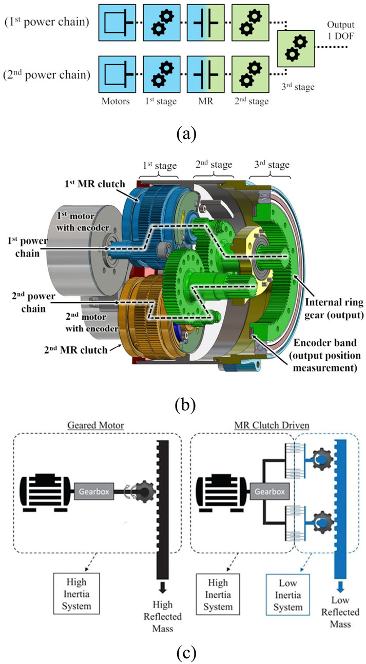
Figure 1. Proposed architecture of MR actuator using two power chains. (a) Schematic view of the two power chains, depicting the motors, pre-clutch gearing, MR clutches, actuator gearing and output. (b) Detailed view of a MR actuator, showing the motors, MR clutches and gearing. (c) Schematic comparison of a geared motor with a high reflected mass at the output and a MR clutch driven actuator with a low reflected mass at the output from its low inertia system (Véronneau et al., 2023).
Geared MR actuators do have limitations. First, they are mechanically complex since they use two mechanical chains per actuator, doubling the number of components with two motors/drives and two separate gearing chains. Assembling such actuators is time consuming, and must be done with care to minimize assembly errors. Second, geared MR actuators have gears between the MR clutches and actuator output. The imperfections of these gears cannot be filtered out by the fluidic interface and the gearing quality must be high.
St-Jean developed and verified a collision model on a tendon-driven 3 DOF MR robot with actuators delocalized to its base, showing that MR actuators are promising in mechatronic applications such as 3 DOF tendon robots and 6 DOF serial chain configuration, with control strategies exploiting the fast reaction of MR actuators being a key element (St-Jean et al., 2024). However, no such 6 DOF MR robots existed at the time of St-Jean’s study and the design space of geared MR actuators for serial-chain cobots is still unknown. Data is non-existent concerning the interactions between joint size, gearing ratio, performance, and human safety.
This paper provides a first understanding of the design space of geared MR actuators for serial-chain cobot applications by systematically studying the impact of gearing ratio of each actuator in the chain on the safety potential. Understanding the effect of the actuator gearing ratio is key to the maximization of the safe speed of robots. Getting a complete mapping of the full design space is well beyond this work. The aim here is to focus on the main design parameter, that is the gearing ratio, and to identify dominant design trends backed by experimentally validated model predictions. Since this work is a first study, orders-of-magnitude precision levels are judged sufficient.
The paper starts off by developing a theoretical modeling framework predicting the equivalent collision mass of a 6 degrees of freedom (DOF) cobot including the effects of the mass and inertia of geared MR actuators along with gearing ratio. The model is then validated experimentally by performing collisions on two 6 DOF cobots, one powered with MR actuators, and one being a commercial reference product using harmonic drives. This paper is the first to present experimental collision data of a MR-powered 6 DOF serial chain robot. Finally, the model is used to study the effect of gearing ratio on selected cobot configurations and basic design guidelines are drawn. The model uses modeling techniques commonly found in robotics, but here applied in the context of MR actuators.
2 Materials and methods
2.1 Collision model and ISO/TS 15066 safety standard
The ISO/TS 15066 Standard defines the maximum safe speed of a cobot’s end-effector based on an energy transfer collision model with a human. While the ISO/TS 15066 Standard outlines multiple safety requirements for cobots, this paper focus only on the maximum collision force as it is generally considered as the most restrictive and challenging criteria to satisfy. The model considers that the kinetic energy
The collision model used in this work is described in St-Jean et al. (2024) and is briefly recalled here for completeness. The model considers rigid bodies and the conservation of momentum of a collision in one dimension, such as shown in Figure 2, where
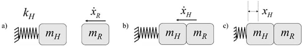
Figure 2. 1-D collision model when masses are: (a) pre-impact, (b) at the instant of impact, and (c) post-impact where maximal force is reached. Adapted from St-Jean et al. (2024).
The maximum collision force
where
2.2 6 DOF cobot dynamic model
A
where
where
An operational coordinate system associated with the base of the robot, which is fixed, is used to find the
involving
where
where
where
This way,
To determine
such that:
where
where
From Equations 5, 6, 9, if
Note that Equation 13 has the same form as Equation 9 showing a relation between reflected mass and the sum of the structural and actuator inertia, see Equation 14:
Actuator mass and inertia models are developed hereafter to define
2.3 Actuator mass and inertia analysis framework
Scaling laws for geared MR actuator’s mass and inertia are only emerging. A first set of scaling laws have been developed for actuator benchmarking purposes (Plante et al., 2025) and are recalled hereafter for completeness of this paper studying the effect of gearing ratio on serial-chain robot safety. Geared MR actuators are a new design paradigm and have no known scaling laws. Therefore, this section develops first order scaling laws for mass and inertia properties that can capture the effect of gearing ratio. These same scaling laws are derived such that they can be used for classic harmonic drive gearmotors taken here as a benchmarking reference.
Geared MR actuator’s mass and inertia properties are derived from experimentally validated parameters from 3 design generations.
1. Gen1 is the first generation of geared MR actuator prototypes and uses basic, single loadpath spur gearing and drum-type MR clutch technology. The actuator gearing ratio (between clutch and output) is 20.4:1 and the pre-clutch ratio (between motor and clutch) is 4.8:1. Maxon EC45 80W motors are used. Gen1 actuators have been built and tested (Véronneau et al., 2023).
2. Gen2 is the second generation of geared MR actuators improving over the Gen1 by introducing multiple loadpath gearing while keeping well-proven drum clutches. The gearing uses 3 planets epicyclic geartrains with dual output idlers. The actuator gearing ratio is 57:1 and the pre-clutch ratio is 3.96:1. Maxon EC45 80W motors are used. Gen2 actuators have been built and tested (Plante et al., 2025).
3. Gen3 is the third generation of geared MR actuators improving over the Gen2 by introducing low inertia and low friction 3D printed disk clutches while keeping multiple loadpath gearing. The gearing uses the same 57:1 epicyclic gearing of the second generation but with an additional 2:1 stage bringing the total actuator gearing to 114:1. The pre-clutch ratio is 1:1. TQ 5014 frameless brushless motors are used. Gen3 actuators have not been fabricated yet and represent a realistic design boundary pushing gearing as high as possible toward the upper bounds of the MR technology.
Universal Robot’s UR3 to UR16 cobots are taken here as a gold standard reference. Their actuators are rated from 12 Nm (size 0) to 330 Nm (size 4) and use Kollmorgen KBM series frameless motors combined to 100:1 harmonic-drives (Boscariol et al., 2020). While a comparison with other actuators from other manufacturers would be beneficial, the choice is made to solely keep the UR systems since: (1) the goal of this study is to compare the MR technology with harmonic drives, not to compare variants of harmonic drives amongst themselves; and (2) the UR systems were one of the first commercially available cobot technologies and are still today one of the most popular, making them a robust, well respected, common ground for comparison.
Electric motors are used in both geared MR and UR actuators to generate mechanical power. Their basic parameters consist of continuous torque
Motor loading is expressed with Equation 15 by an overload factor
The peak-to-continuous torque ratio
The analysis framework is based on the concept of an actuator’s brake torque
The mechanical efficiency
Only torque destroying mechanisms such as Coulomb and viscous friction in bearings and gears influence the mechanical efficiency. Clutch slippage has no effect on mechanical efficiency since torque is preserved through a slipping clutch. Slippage therefore only influences energy conversion efficiency with a velocity loss during slipping.
The mechanical efficiency of actuator gearing, be it spur, planetary or harmonic, fundamentally depends on gearing ratio and output speed. Given that the gearing ratios considered in this study are in a relatively narrow range (50:1 to 150:1), and that the output speeds are relatively low (around 10 to 30 RPM), a first simplifying assumption is made by using a constant mechanical efficiency value of 0.85 for both harmonic drives and planetary gearing. This value is taken as a global average of manufacturers data, that is conservatively made in favor of harmonic drives whose efficiency drops rapidly, well below 85%, when output speed increases.
Topologies and power flow of conventional and geared MR actuators are shown in Figure 3. In conventional actuators, see Figure 3a, the indicated output torque is the motor’s torque
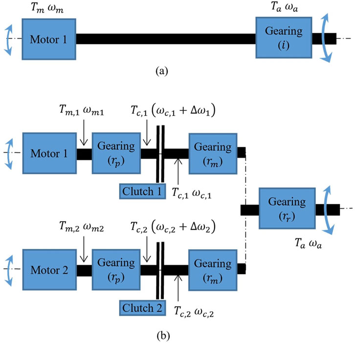
Figure 3. Power flow of (a) conventional gearmotor and (b) geared MR actuator with 2 actuation chains. Adapted from Plante et al. (2025).
In geared MR actuators, unlike most conventional actuators, multiple sub-actuation chains can be used in parallel, see Figure 3b. On the motor side of the clutch, the motor can use a light pre-clutch gearing,
MR fluids in MR clutches behave like Bingham fluids and clutch torque is generated by a magnetically controllable torque,
Assuming linear viscosity, the torque due to shear stress is defined by Equation 20:
where
Referring to Figure 3b shaft speeds through the clutches is controlled such that a clutch’s input speed is always higher than its output
where
The following subsections develop relationships between an actuator’s brake torque and its mass and inertia, expressed as Torque-to-mass and Torque-to-inertia ratios, respectively. Note that the analytical development contains many simplifying assumptions that were necessary to obtain closed-form expressions. This is judged acceptable for a preliminary analysis such as intended in this paper.
2.4 Actuator torque-to-mass
Geared MR actuators have 6 component groups: motor(s), pre-clutch gearing(s), clutch(s), main gearing(s), recombination gearing, and frame. The total mass
where
where
Equation 29 holds for conventional actuators as well by setting
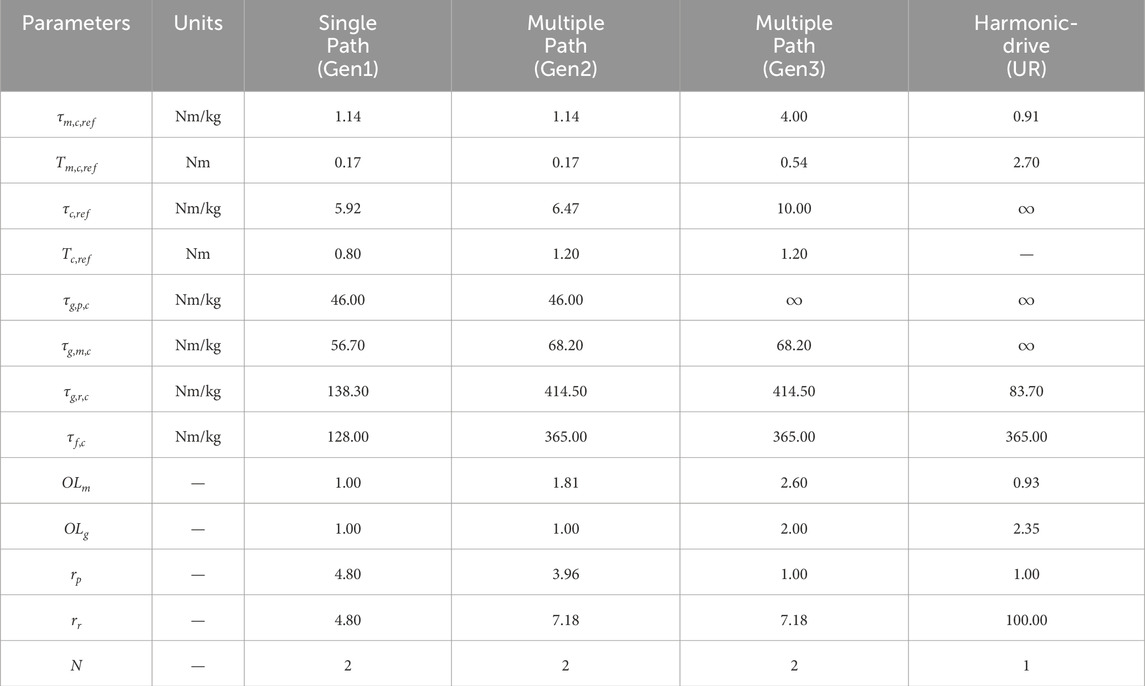
Table 1. Data for the calculation of the torque-to-mass ratio.
Overload factors for harmonic drives are estimated from component manufacturers data while those of geared MR actuator designs were selected based on growing confidence as prototype generations evolve. The first generation used a conservative
Motor and clutch torque-to-mass vary non-linearly with size as shown in Figures 4, 5, such that they can be defined by Equations 30, 31:
where
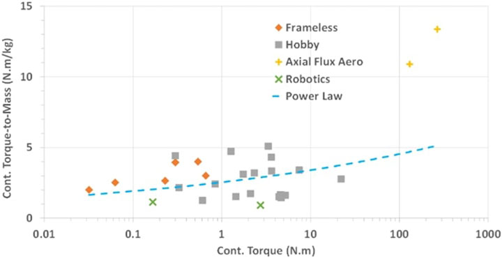
Figure 4. Motor torque-to-mass vs. motor torque data extracted from various commercially available motors. Adapted from Plante et al. (2025).
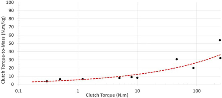
Figure 5. MR clutch mass vs. clutch torque data extracted from various MR clutch designs built over the years. Adapted from Plante et al. (2025).
Disk clutches as in the Gen3 have not been studied as much as drum clutches. First measurements on a 3D printed disk clutch prototype showed twice the torque density of the drum clutches of the Gen2 generation (Lhommeau et al., 2023). Although the torque-to-mass of both disk and drum clutches could be further optimized, a conservative torque density boundary is set for disk clutches as a fraction of drum clutches such that
2.5 Actuator torque-to-inertia
Geared MR actuator output inertia is the sum of the clutches and gearing reflected inertia,
The torque-to-inertia ratio is then defined by Equation 35:
which can be rewritten as Equation 36:
where
Now, the inertia of planetary and parallel shaft (spur) gears scales with
where
where
In geared MR actuators, the majority of gearing inertia comes from the main gearing stage. Applying Equation 40 to the main gearing stage gives Equation 41:
The gearing-to-clutch inertia ratio is then defined by Equation 42:
Substituting back into Equation 36 gives Equation 43:
Gearing diameter can be expressed in non-geometrical parameters to eliminate all dimensionality. Since gearing torque scales with volume (Saerens et al., 2019), the main gearing torque scaling law with volume is defined with Equation 44:
Finding an expression between gearing length and diameter would eliminate all dimensional quantities from Equation 43, simplifying the analysis. Inspecting manufacturers data (for example, compare Harmonic Drive’s planetary drives HPG size 20 and size 50) suggests that it is reasonable, at least in first approximation, to assume that gearing length is roughly proportional to output torque with a power of 0.3. This means that a ten fold increase in torque doubles the length such that:
Equation 45 is assumed to hold for all gearing type, harmonic or planetary. In any case, it has been verified that the torque to length relation of Equation 45 has a second order effect on model predictions and does not change conclusion of the work. Then, Equation 46:
allows to obtain Equation 47:
Equation 43 shows that minimizing gearing diameter is critical for high torque-to-inertia, which, as shown by Equation 47, is done by using multiple actuation chains

Table 2. Data for the calculation of the torque-to-inertia ratio.
For conventional actuators, MR clutch properties are simply replaced by motor properties in Equations 43 or 47. Also, gearing reduction is entirely done in the recombination gearing stage such that
Equations 47, 48 show that the main design parameters are related to actuator size (torque output
Finally, the inertia correction factor
The correction factor
Here again, motor and drum-type clutch torque-to-inertia vary non-linearly with size. The torque-to-inertia
If
Since
The scaling law of Equation 50 is assumed to hold for disk MR clutches and for electric motors since they are all similar electromechanical machines. A general relationship for conventional actuators is then defined by Equation 53:
2.6 Experimental validation
Collision tests are carried out on an Exonetik MR5 cobot to verify the Torque-to-Mass and Torque-to-Inertia ratios as well as the collision model accuracy. The MR5 is a development robot not available commercially. The MR5 shares the UR5e architecture, payload and workspace but uses MR actuators with a maximum joint torque of 140 Nm in combined slip mode. The MR actuators are Gen2 designs with drums-type clutches and multiple loadpath gearing.
The experiments are based on those carried in previous work (St-Jean et al., 2024) using the same test bench. They consist of first positioning the robots with a known joint configuration, far from kinematic singularities; then commanding a linear trajectory to reach a collision point at a second joint configuration with a known collision speed. The trajectory is determined to reach a collision perpendicular to the surface such as in the ISO/TS 15066 Standard. A uniaxial force sensor under the mass-spring (0.6 kg, 75 N/mm) representing a human at the collision point allows to measure contact forces. The experimental setup is presented in Figure 6.

Figure 6. Experimental setup of the collision tests carried out on the MR actuated cobot MR5.
Measured impact forces are presented in Figure 7 alongside model predictions. The collision test results carried out by St-Jean (St-Jean et al., 2024) on the UR5 are also compared in Figure 7 to the model predictions. Both robots show good fit between the predictions and the experimental values, even considering the multiple assumptions made in the actuator mass and inertia models, with
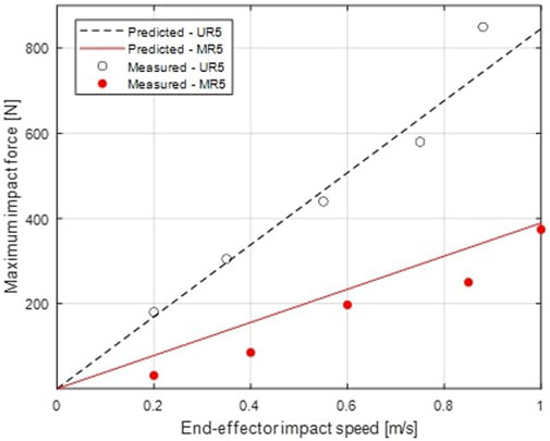
Figure 7. Measured maximum impact force from a collision test compared to the model prediction, as a function of end-effector impact speed, for both UR5 and MR5 cobots.
2.7 Robot reflected mass performance metric
A performance metric must be derived to evaluate the general safety of a robot over its entire workspace to compare various robot designs. Many metrics from the literature have been considered such as the reflected mass of a constant operational direction, the Mean Reflected Mass (MRM) (Steinecker et al., 2022), the Generalized Impact Measure (GIM) (Walker, 1994) and the volume of the mass ellipsoid (Song et al., 2020). The volume of the mass ellipsoid, which defines a reflected mass for every directional vector, represents the overall impact strength, but cannot directly transpose to an effector speed and could lead to false impressions of safety when the ellipsoid is skewed with a specific direction having a huge reflected mass despite a small ellipsoid volume. The GIM expresses the difficulty for a human to move the end-effector along a trajectory but is devoid of any physical interpretation (Steinecker et al., 2022). The MRM optimization showed a correlation with lower forces in collision, but lacks an analytical expression, hence has unclear mathematical relationship with the robot configuration (Steinecker et al., 2022).
The choice is made to use the median of the maximal reflected masses of numerous robot’s poses over its workspace, described here as the Global maximal reflected mass
It should be noted that some of the metrics discussed above were implemented and compared to the
In this study, we limit ourselves to robot architectures identical to, or derived from UR robots because, as explained before, they represent a well known gold standard reference.
Robot joint configurations selected for
In all, unless otherwise noted, all optimizations run in this paper aim to find the optimal global gearing ratio
Four analyses are performed: (1) a global gearing ratio
3 Results
Results are expressed in terms of reflected masses at end-effector. When relevant, the reflected masses are translated to maximum safe speeds according to ISO/TS 15066 Standard (ISO, 2016). Also, it is worth recalling that the global gearing ratio
3.1 Influence of gearing ratio on
The effect of gearing ratio on
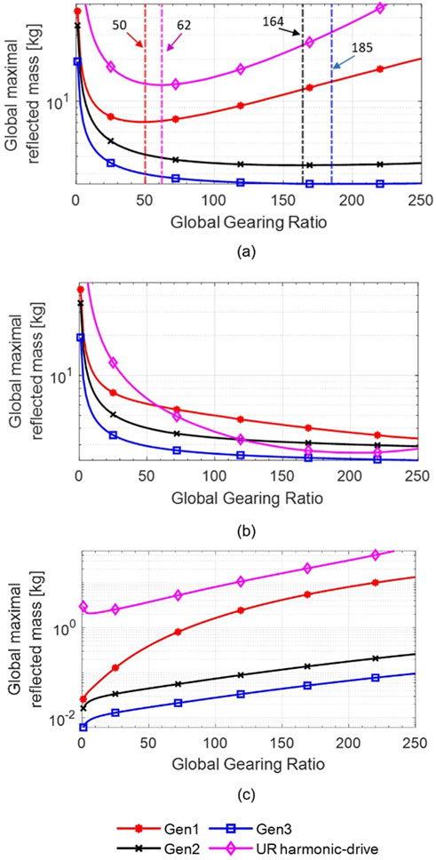
Figure 8. Results from the analytical model for the global maximal reflected mass
Figure 8b shows the reduction of the reflected mass associated with the reduction of the structural mass as the gearing ratio increases, while Figure 8c shows the increase of the reflected mass associated with the increase of actuator’s output inertia following the gearing ratio increase. These opposing trends create the presence of
The reduction of the reflected mass between the studied actuators and 100:1 HD actuators,
where
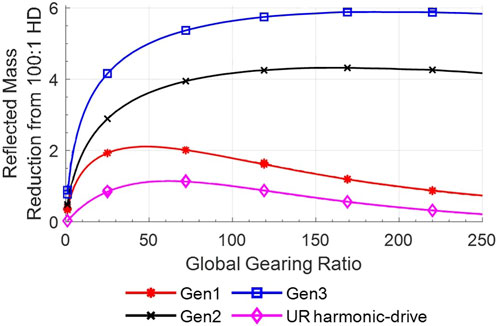
Figure 9. Results from the analytical model for the reduction ratio of the reflected mass
The improvement factors of Figure 9 suggest that MR actuators have the potential to reduce the reflected mass by a factor ranging from
It should be noted that the maximum actuator safe speed associated with the calculated optimal
3.2 Influence of robot reach on
The effect of varying robot reach and gearing on a map of
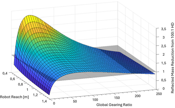
Figure 10. Results from the analytical model for the reflected mass reduction from the use of Gen1 actuators instead of 100:1 Harmonic-Drive actuators
3.3 Influence of delocalization on
The effect of delocalizing wrist actuators to the elbow of a UR5e robot is shown on Figure 11. Figure 11a is similar to Figure 8c, but
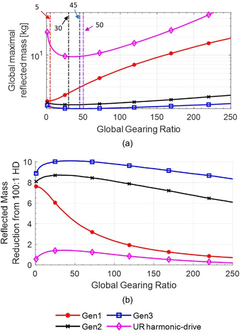
Figure 11. Results from the analytical model for the (a) Global maximal reflected mass
3.4 Influence of multiple gearing ratios on
So far in this paper, actuators of a given robot configuration all used the same gearing ratio. Theoretically, further reflected mass reductions are possible if each joint/actuator has it’s own gearing ratio. The optimal gearing ratios of the actuators studied in this paper when used on a UR5e configuration are shown in Table 3.
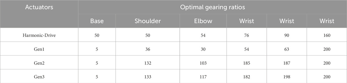
Table 3. Results from the analytical model for the optimal gearing ratios from the multiple gearing ratios
Table 4 shows the comparison of
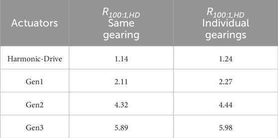
Table 4.
4 Discussion
4.1 Design guidelines
The work gave a first description of the design space of geared MR actuators used in serial-chain cobots by studying how much gearing can be used between the MR actuators and the joint outputs while remaining safe to humans.
The following design guidelines can be drawn:
Design guideline 1: From a safety standpoint according to ISO/TS 15066 Standard, MR actuators have potential of producing a lower Global maximal reflected mass
Design guideline 2: Optimal gearing ratios are highly dependent on MR actuator torque and inertia densities. From the generations analyzed in this study, the Gen1 actuator (single load-path, drum-clutch) presents a clear gearing ratio optimum value around 50:1, while the better performing Gen2 (multiple load-path, drum-clutch) and Gen3 actuators (multiple load-path, disk-clutch) have no optimal values within the 200:1 gearing ratio bound used in this study. The implication is that geared MR actuator must reach a certain threshold level of torque/inertia density to use high gearing ratios. With the current state of technology, this necessitates the use of multiple shear interfaces in the MR clutches (e.g., multi-disk or multi-drum configurations) and multiple contact points gearing (e.g., 3 planets planetary gearing).
Design guideline 3: For given actuator torques, the performance improvement potential of MR actuators decreases with robot size or reach. Indeed, smaller robots with smaller reach better exploit the advantages of MR actuators since most of their reflected mass comes from actuator rotational inertia. As robot size increases, reflected mass shifts to structural rather than inertial mass.
Design guideline 4: Actuator delocalization such as bringing the wrist actuators to the elbow removes structural mass and thus shifts the optimal global gearing ratio to lower ratios. With more emphasis on inertial mass, the performance potential of MR actuators also increases, and the studied delocalized robot showed a
Design guideline 5: Optimizing a serial chain robot with a distinct gearing ratio for each actuator does not significantly reduce
4.2 Limitations
Results of this paper should be used with care since it is only a first step toward understanding the design space of MR-powered robots. Fully understanding the design space of a technology with extensive experimental and analytical results covering all possible designs is a massive effort that cannot be done in a single research paper. Accordingly, the work presented here has important limitations, with two important ones being:
1- The analytical model of the geared MR actuator mass and inertia has many simplifications that were necessary to extract workable closed-form analytical formulations. The model is assumed valid over the range of its experimental calibration, here limited to three similar actuator designs (Gen 1,2,3). Model validity is unknown past its calibration range, for example, when considering widely varying geared MR actuator designs.
2- The study is limited to a single 6 DOF robot architecture based on the UR5e and its harmonic drive actuator design. The conclusions of this paper are only deemed valid for the UR5e geometry and may not apply to other robot and/or actuator designs.
4.3 Future works
Future works should improve the richness of knowledge by studying different geared MR actuator designs in different robot geometries to bring new data points. Further investigations should also be done toward other critical robot metrics regarding the effect of gearing ratio on stiffness, bandwidth, backdrivability, disturbance rejection, etc. At last, more collision data of 6 DOF robots using various MR actuator designs are needed to fully validate the proposed collision model over the full workspace.
Data availability statement
The raw data supporting the conclusions of this article will be made available by the authors, without undue reservation.
Author contributions
SG: Writing – original draft, Writing – review and editing. AS-J: Writing – review and editing. J-SP: Writing – review and editing.
Funding
The author(s) declare that financial support was received for the research and/or publication of this article. We would like to thank the NSERC-CREATE CoRoM program for their financial support of this research.
Acknowledgments
We would like to thank Exonetik for allowing us to use their MR5 robot.
Conflict of interest
The authors declare that the research was conducted in the absence of any commercial or financial relationships that could be construed as a potential conflict of interest.
Generative AI statement
The author(s) declare that no Generative AI was used in the creation of this manuscript.
Publisher’s note
All claims expressed in this article are solely those of the authors and do not necessarily represent those of their affiliated organizations, or those of the publisher, the editors and the reviewers. Any product that may be evaluated in this article, or claim that may be made by its manufacturer, is not guaranteed or endorsed by the publisher.
References
Avraam, M. T. (2009). MR-fluid brake design and its application to a portable muscular device. (Bruxelles, Belgium: Université Libre de Bruxelles). Ph.D. thesis.
Begin, M.-A., Chouinard, P., Lebel, L.-P., Masson, P., Pasco, Y., Plante, J.-S., et al. (2018). Experimental assessment of a controlled slippage magnetorheological actuator for active seat suspensions. IEEE/ASME Trans. Mechatronics 23, 1800–1810. doi:10.1109/TMECH.2018.2836351
Bernhardt, R., Surdilovic, D., Katschinski, V., Schreck, G., and Schröer, K. (2008). “Next generation of flexible assembly systems,” in Innovation in manufacturing networks. Editor A. Azevedo (Springer US), 279–288. doi:10.1007/978-0-387-09492-2_30
Bluethmann, W., Ambrose, R., Diftler, M., Askew, S., Huber, E., Goza, M., et al. (2003). Robonaut: a robot designed to work with humans in space. Aut. Robots 14, 179–197. doi:10.1023/A:1022231703061
Bo, H., Mohan, D. M., Azhar, M., Sreekanth, K., and Campolo, D. (2016). “Human-robot collaboration for tooling path guidance,” in 2016 6th IEEE international conference on biomedical robotics and biomechatronics (BioRob) (IEEE), 1340–1345. doi:10.1109/BIOROB.2016.7523818
Boscariol, P., Caracciolo, R., Richiedei, D., and Trevisani, A. (2020). Energy optimization of functionally redundant robots through motion design. Appl. Sci. 10, 3022. doi:10.3390/app10093022
Byner, C., Matthias, B., and Ding, H. (2019). Dynamic speed and separation monitoring for collaborative robot applications – concepts and performance. Robotics Computer-Integrated Manuf. 58, 239–252. doi:10.1016/j.rcim.2018.11.002
Chouinard, P., Bégin, M.-A., Marchetta Fortin, J., Berry, A., Masson, P., and Plante, J.-S. (2018). “Preventing lower back pain among truck drivers: design and performance of a controlled slippage magnetorheological actuator for an active seat suspension,” in Proceedings of the ASME 2018 international design engineering technical Conferences and Computers and Information in engineering conference. Vol. Volume 5A: 42nd mechanisms and robotics conference of international design engineering technical Conferences and Computers and Information in engineering conference. V05AT07A063. doi:10.1115/DETC2018-85681
Denis, J., Lecavalier, A., Plante, J.-S., and Girard, A. (2022). “Multimodal hydrostatic actuators for wearable robots: a preliminary assessment of mass-saving and energy-efficiency opportunities,” in 2022 international conference on robotics and automation (ICRA), 8112–8118. doi:10.1109/ICRA46639.2022.9812435
Duchaine, V., Lauzier, N., Baril, M., Lacasse, M.-A., and Gosselin, C. (2009). “A flexible robot skin for safe physical human robot interaction,” in 2009 IEEE international Conference on Robotics and automation (IEEE), 3676–3681. doi:10.1109/ROBOT.2009.5152595
East, W., Turcotte, J., Plante, J.-S., and Julio, G. (2021). Experimental assessment of a linear actuator driven by magnetorheological clutches for automotive active suspensions. J. Intelligent Material Syst. Struct. 32, 955–970. doi:10.1177/1045389X21991237
Fauteux, P., Lauria, M., Heintz, B., and Michaud, F. (2010). Dual-differential rheological actuator for high-performance physical robotic interaction. IEEE Trans. Robotics 26, 607–618. doi:10.1109/TRO.2010.2052880
Gambao, E., Hernando, M., and Surdilovic, D. (2012). “A new generation of collaborative robots for material handling,” in 29th international symposium on automation and robotics in construction; held jointly with the 8th world conference of the international society for gerontechnology. Editors J. van Bronswijk, G. J. Maas, and F. J. van Gassel (Eindhoven, Netherlands: International Association for Automation and Robotics in Construction IAARC). doi:10.22260/ISARC2012/0076
García, P. L., Crispel, S., Saerens, E., Verstraten, T., and Lefeber, D. (2020). Compact gearboxes for modern robotics: a review. Front. Robotics AI 7, 103. doi:10.3389/frobt.2020.00103
Gervais, M., Lebel, L.-P., and Plante, J.-S. (2022). “Design exploration and experimental characterization of a 6 degrees-of-freedom robotic manipulator powered by cable-driven semi-delocalized magnetorheological actuators,” in 2022 international conference on robotics and automation (ICRA), 11416–11423. doi:10.1109/ICRA46639.2022.9812275
Julio, G., Plante, J. S., and Latham, G. (2015). “Development of a magneto-rheological fluid-based trim actuator with active tactile cueing capabilities,” in 71st American helicopter society international annual forum 2015 (American helicopter society) (Elsevier Inc), 2, 1086–1094. Compilation and indexing terms, Copyright 2022.
Khatib, O. (1995). Inertial properties in robotic manipulation: an object-level framework. Int. J. Robotics Res. 14, 19–36. doi:10.1177/027836499501400103
Khazoom, C., Caillouette, P., Girard, A., and Plante, J.-S. (2020). A supernumerary robotic leg powered by magnetorheological actuators to assist human locomotion. IEEE Robotics Automation Lett. 5, 5143–5150. doi:10.1109/LRA.2020.3005629
Khazoom, C., Veronneau, C., Bigue, J.-P. L., Grenier, J., Girard, A., and Plante, J.-S. (2019). Design and control of a multifunctional ankle exoskeleton powered by magnetorheological actuators to assist walking, jumping, and landing. IEEE Robotics Automation Lett. 4, 3083–3090. doi:10.1109/LRA.2019.2924852
Kim, H.-S., Kim, I.-M., Cho, C.-N., and Song, J.-B. (2012). Safe joint module for safe robot arm based on passive and active compliance method. Mechatronics 22, 1023–1030. doi:10.1016/j.mechatronics.2012.08.007
Kufieta, K. (2014). Force estimation in robotic manipulators: modeling, simulation and experiments. (Trondheim, Norway: Norwegian University of Science and Technology). Ph.D. thesis.
Lhommeau, P., Lamy, M., and Plante, J.-S. (2023). Design and characterization of a miniaturized low inertia and low viscous friction magnetorheological clutch using 3d metal printing for human-robot applications. J. Intelligent Material Syst. Struct. 34, 1633–1645. doi:10.1177/1045389X221147675
Lynch, K. M., and Park, F. C. (2016). Modern robotics: mechanics, planning, and control. 1st edn. Cambridge, UK: Cambridge University Press.
Moghani, M., and Kermani, M. R. (2020). A lightweight magnetorheological actuator using hybrid magnetization. IEEE/ASME Trans. Mechatronics 25, 76–83. doi:10.1109/TMECH.2019.2951340
Najmaei, N., Asadian, A., Kermani, M. R., and Patel, R. V. (2015). “Magneto-rheological actuators for haptic devices: design, modeling, control, and validation of a prototype clutch,” in 2015 IEEE international conference on robotics and automation (ICRA), 207–212. doi:10.1109/ICRA.2015.7139001
Peshkin, M., Colgate, J., Wannasuphoprasit, W., Moore, C., Gillespie, R., and Akella, P. (2001). Cobot architecture. IEEE Trans. Robotics Automation 17, 377–390. doi:10.1109/70.954751
Pisetskiy, S., and Kermani, M. R. (2018). “Development of mr clutch for a prospective 5 dof robot,” in 2018 IEEE/RSJ international conference on intelligent robots and systems (IROS), 5900–5905. doi:10.1109/IROS.2018.8593582
Plante, J.-S., St-Jean, A., and Lucking Bigué, J.-P. (2025). Bridging the gap between haptic devices and cobots with highly geared magnetorheological actuators. Sci. Rep. 15, 14363. doi:10.1038/s41598-025-98999-6
Saerens, E., Crispel, S., García, P. L., Verstraten, T., Ducastel, V., Vanderborght, B., et al. (2019). Scaling laws for robotic transmissions. Mech. Mach. Theory 140, 601–621. doi:10.1016/j.mechmachtheory.2019.06.027
Sanneman, L., Fourie, C., and Shah, J. A. (2020). The state of industrial robotics: emerging technologies, challenges, and key research directions
Sensinger, J. W., Clark, S. D., and Schorsch, J. F. (2011). “Exterior vs. interior rotors in robotic brushless motors,” in 2011 IEEE international Conference on Robotics and automation (IEEE), 2764–2770. doi:10.1109/ICRA.2011.5979940
Seok, S., Wang, A., Chuah, M. Y., Hyun, D. J., Lee, J., Otten, D. M., et al. (2015). Design principles for energy-efficient legged locomotion and implementation on the mit cheetah robot. IEEE/ASME Trans. Mechatronics 20, 1117–1129. doi:10.1109/TMECH.2014.2339013
Shafer, A. S., and Kermani, M. R. (2011). “Design and validation of a magneto-rheological clutch for practical control applications in human-friendly manipulation,” in 2011 IEEE international conference on robotics and automation, 4266–4271. doi:10.1109/ICRA.2011.5980258
Song, S., She, Y., Wang, J., and Su, H.-J. (2020). Toward tradeoff between impact force reduction and maximum safe speed: dynamic parameter optimization of variable stiffness robots. J. Mech. Robotics 12. doi:10.1115/1.4046839
Steinecker, T., Kurdas, A., Mansfeld, N., Hamad, M., Kirschner, R. J., Abdolshah, S., et al. (2022). Mean reflected mass: a physically interpretable metric for safety assessment and posture optimization in human-robot interaction. Int. Conf. Robotics Automation (ICRA), 11209–11215. doi:10.1109/ICRA46639.2022.9811582
St-Jean, A., Dorval, F., Plante, J.-S., and Lussier-Desbiens, A. (2024). Magnetorheological-actuators: an enabling technology for fast, safe, and practical collaborative robots. IEEE Trans. Robotics 40, 1261–1272. doi:10.1109/TRO.2023.3341573
Ulmen, J., and Cutkosky, M. (2010). “A robust, low-cost and low-noise artificial skin for human-friendly robots,” in 2010 IEEE international conference on robotics and automation (IEEE), 4836–4841. doi:10.1109/ROBOT.2010.5509295
Veronneau, C., Denis, J., Lebel, L.-P., Denninger, M., Blanchard, V., Girard, A., et al. (2020). Multifunctional remotely actuated 3-dof supernumerary robotic arm based on magnetorheological clutches and hydrostatic transmission lines. IEEE Robotics Automation Lett. 5, 2546–2553. doi:10.1109/LRA.2020.2967327
Véronneau, C., Denis, J., Lebel, L.-P., Denninger, M., Plante, J.-S., and Girard, A. (2019). “A lightweight force-controllable wearable arm based on magnetorheological-hydrostatic actuators,” in 2019 international conference on robotics and automation (ICRA), 4018–4024. doi:10.1109/ICRA.2019.8793978
Véronneau, C., Denis, J., Lhommeau, P., St-Jean, A., Girard, A., Plante, J.-S., et al. (2023). Modular magnetorheological actuator with high torque density and transparency for the collaborative robot industry. IEEE Robotics Automation Lett. 8, 896–903. doi:10.1109/LRA.2022.3231524
Viau, J., Chouinard, P., Bigue, J.-P. L., Julio, G., Michaud, F., and Plante, J.-S. (2017). Tendon-driven manipulator actuated by magnetorheological clutches exhibiting both high-power and soft motion capabilities. IEEE/ASME Trans. Mechatronics 22, 561–571. doi:10.1109/TMECH.2016.2605379
Walker, I. (1994). Impact configurations and measures for kinematically redundant and multiple armed robot systems. IEEE Trans. Robotics Automation 10, 670–683. doi:10.1109/70.326571
Keywords: robot safety, collaborative robots, magnetorheological clutch, actuator, robot architecture, gearing ratio, physical human-robot interaction
Citation: Gingras S, St-Jean A and Plante J-S (2025) Preliminary investigation of the design space of geared magnetorheological actuators for safer robotic manipulators. Front. Robot. AI 12:1581651. doi: 10.3389/frobt.2025.1581651
Received: 25 February 2025; Accepted: 19 May 2025;
Published: 05 June 2025.
Edited by:
Carlos Rossa, Carleton University, CanadaReviewed by:
Lucas Ferrari Gerez, University of Glasgow, United KingdomGuillermo Javier Amador, Wageningen University and Research, Netherlands
Pablo Lopez Garcia, Vrije University Brussels, Belgium
Chao Shen, Carleton University, Canada
Copyright © 2025 Gingras, St-Jean and Plante. This is an open-access article distributed under the terms of the Creative Commons Attribution License (CC BY). The use, distribution or reproduction in other forums is permitted, provided the original author(s) and the copyright owner(s) are credited and that the original publication in this journal is cited, in accordance with accepted academic practice. No use, distribution or reproduction is permitted which does not comply with these terms.
*Correspondence: Samuel Gingras, c2FtdWVsLnAuZ2luZ3Jhc0B1c2hlcmJyb29rZS5jYQ==