 Chengren Yuan
 Changgeng Shuai1,2
 Zhanshuo Zhang
- 1Institute of Noise and Vibration, Naval University of Engineering, Wuhan, China
- 2National Key Laboratory on Ship Vibration and Noise, Wuhan, China
Marine vehicle guidance and control technology serves as the core support for advancing marine development and enabling scientific exploration. Its accuracy, autonomy, and environmental adaptability directly determine a vehicle’s mission effectiveness in complex marine environments. This paper explores path following for marine vehicles in the horizontal plane. To tackle the limitation of a fixed look-ahead distance, we develop a novel geometric line-of-sight guidance law. It adapts to diverse compound paths by dynamically adjusting according to cross-track errors and local path curvature. Then, to enhance control performance, we present an improved exponential switching law for sliding mode control, enabling rapid convergence, disturbance rejection, and chatter reduction. Additionally, integral sliding mode control is integrated to stabilize yaw angular velocity, ensuring the system’s global asymptotic stability. Through a series of numerical simulations, the effectiveness, robustness, and adaptability of our proposed methods are verified.
1 Introduction
Marine vehicles, particularly those emphasizing autonomy and intelligence, have gained significant importance (Xu and Pan, 2022; Song et al., 2024a). Unmanned marine vehicles such as USVs and UUVs demonstrate high efficiency in marine resource surveying and development (Wang et al., 2023; Rong and Xu, 2022). However, ensuring optimal control performance remains critical for successful mission execution (Heshmati-Alamdari et al., 2020; Song et al., 2024b).
The control system framework is typically divided into three distinct components: guidance, navigation, and control (GNC) (Fossen, 2011). Uncertainties in models, time-varying oceanic environments, and actuator limitations pose significant challenges for constructing path-following controllers (Kim et al., 2021; Wang et al., 2024). While previous studies, such as Yu et al. (2019); Elmokadem et al. (2017); Lei and Zhang (2017); Reis et al. (2019); Qiao and Zhang (2019), have focused on integrating the guidance and control layers to improve path-following accuracy, many overemphasize control law design for accuracy while neglecting actuator constraints (Yu et al., 2019; Song et al., 2025). Therefore, researching guidance laws to enhance overall GNC system performance and maintain balance among its components is essential.
The line-of-sight (LOS) guidance law is intuitively designed for helmsmen, enabling vehicles to reach desired positions by maintaining alignment with the look-ahead angle (Fossen, 2011; Fossen and Pettersen, 2014). Encarnacao and Pascoal (2000) projected the UUV into a 3D Serrent-Frenet frame and designed a controller integrating the desired path’s kinematic characteristics with the UUV’s dynamic model. However, this method suffered from complexity and singularity issues. To address these, Breivik and Fossen (2005b) introduced a virtual reference point on the desired path within the Serrent-Frenet frame, developing a classical non-singular LOS guidance law for 2D and 3D path following. Yet, this law remained sensitive to ocean currents and used a fixed look-ahead angle. Subsequent studies (Borhaug et al., 2008; Fossen et al., 2014; Fossen and Lekkas, 2017; Miao et al., 2017) focused on mitigating current vulnerability. For instance, Miao et al. (2017) proposed a compound LOS guidance law to estimate sideslip angles and compensate for time-varying current effects in the horizontal plane. Despite these advancements, engineering practice still demands an LOS guidance law with automatic look-ahead angle adjustment. Wang et al. (2022) addressed this by introducing an adaptive LOS guidance law via reinforcement learning, dynamically adjusting the look-ahead angle using a data-driven UUV model. Mu et al. (2018) employed a fuzzy optimization approach to determine optimal look-ahead distances for surface vessels, using Euclidean distances between virtual target points and current positions as fuzzy logic inputs. Xiang et al. (2015) dynamically adjusted look-ahead distances based on path curvature via virtual target points, though these points did not fully reflect real-time vehicle positions.
In the GNC system, control law design is crucial for path following, second only to the guidance system block. Sliding mode control (SMC) is widely adopted to address environmental disturbances and model uncertainties due to its high robustness (Roy et al., 2020). For instance, Elmokadem et al. (2017) proposed terminal SMC (TSMC), fast TSMC (FTSMC), and non-singular TSMC (NTSMC) as effective approaches to reduce following errors under environmental disturbances. To overcome the singularity issue in traditional TSMC, Lei and Zhang (2017) developed an adaptive non-singular integral TSMC scheme, ensuring local finite-time convergence of velocity and position errors to zero. Tutsoy and Barkana (2021) introduced a model-free digital adaptive control for under-actuated manipulators, capable of handling delays, saturations, and uncertainties. This method also extended to chaos control, enabling the learning of unbiased smooth policies in chaotic regions, and real-time experiments verified its accurate long-term prediction and control performance. Moreover, Ma et al. (2023) presented a novel actor-model-critic architecture that combines a neural network model with the traditional actor-critic framework. The neural network model was designed to learn the state transition function, exploring the spatio-temporal variation patterns of the AUV and its surrounding environment.
This paper proposes a novel geometric LOS (GLOS) guidance law and exponential switching law for the horizontal-plane GNC system of unmanned marine vehicles. The objective is to reduce the control layer’s workload and balance the operational burden between the guidance and control laws, thereby enhancing the GNC system’s robustness and adaptability. The desired trajectory is realized by updating the velocity of a virtual target point via the GLOS guidance law, integrated with integral sliding mode control (ISMC) that employs an adaptively adjusted improved exponential switching law. The main contributions are summarized as follows:
• The GLOS guidance law is designed to adjust the look-ahead distance based on both cross-track errors and local path curvature, thereby avoiding the influence of individual factors such as distance (Liu et al., 2017) or curvature (Xiang et al., 2015) alone.
• An enhanced exponential switching law is proposed for general SMC methods. Compared with the conventional exponential switching law, the proposed law demonstrates better performance in rapid convergence, disturbance rejection, and chatter suppression. Based on this, an ISMC law is developed to stabilize the virtual angular velocity of yaw.
The remainder of this paper is organized as follows: Section 2 introduces the notation for path following and the modeling of marine vehicles. The proposed methods are detailed in Section 3. Section 4 then presents the results of numerical simulations, and Section 5 concludes with a comprehensive summary.
2 Notation and modeling
2.1 Notation
To construct the coordinate system for path following, the following reference frames, including inertial frame
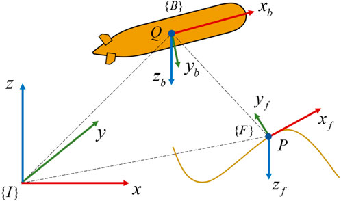
Figure 1. The reference frames for a vehicle.
In Equations 1, 2, set
2.2 Control objective
In path following, the marine vehicle with length
3 Proposed approach
3.1 LOS guidance law and problem
As stated in reference Breivik and Fossen (2005b), the controlled vehicle aligns with the look-ahead angle
where
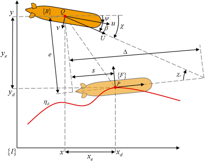
Figure 2. The LOS guidance law for vehicle’s path following control.
Take the time derivative of Equation 4 and simplify it as
To ensure the Lyapunov function Equation 5 is negative-definite, the update rate of
with the LOS guidance law is designed as
where
In Equation 8, the current LOS guidance law features an indeterminate parameter
3.2 GLOS guidance law
In this paper, we explore the geometric relationship between the desired path and vehicle, and further find that the cross-track error
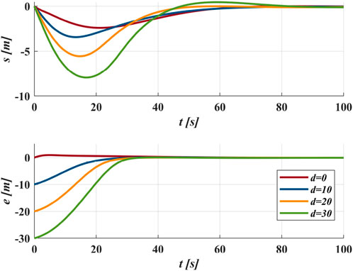
Figure 3. Trace the circular path as
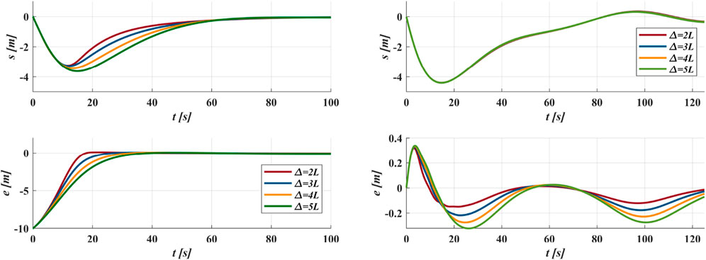
Figure 4. (a) Trace the circular path as
As for the local path curvature
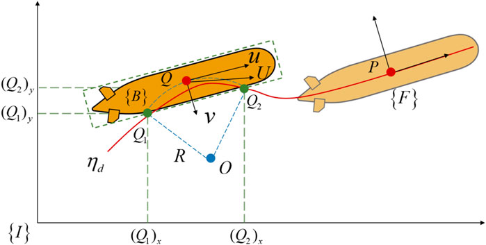
Figure 5. The GLOS guidance law in path following. It use the current path curvature of the vehicle (left vehicle) rather than the virtual target point (right vehicle).
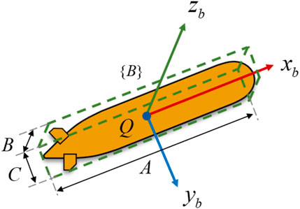
Figure 6. The vehicle in bounding box with parameters.
Combining the cross-track error
In Equation 9,
In the GLOS guidance law,
•The method avoids calculating non-existent curvature at the junction of compound paths.
•The approach prevents oscillations at points where curvature abruptly changes in a compound desired path.
•The adjustable parameters
Set the number of intersections
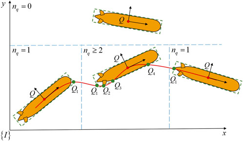
Figure 7. The process of the vehicle following the desired path, it is classified as: (1) Far from the desired path,
Algorithm 1.GLOS.
Input:
Navigation information
Desired path
Output:
Look-ahead angle
Update law
1 Initialize all Parameters;
2 Calculate
3 Update OBB(Q,[
4
5 if
6
7 else
8 if
9
10 else
11
12
13
14
15 Repeat
3.3 Controller design
In Section 3.2, only position error is controlled. According to Section 2.2, the heading error
The time derivative of Equation 10 are derived as
In order to convert
where the control gain is
In order to stabilize
where
Therefore, the yaw DOF controller is designed as
In Equations 16, 17,
where the estimation error of
In order to set
Substitute the adaptive interference law Equation 20 in Equation 19 as
In Equation 21, according to the reference Yuan et al. (2022),
4 Numerical simulations
To verify the GLOS guidance law and improved exponent switching law for path following in the horizontal plane, this paper takes REMUS 100 AUV as the research object and adopts the hydrodynamic parameters from reference Prestero (2001). The main parameters of the proposed scheme are as follows:
4.1 Case I
Case I employs a compound straight-line and curve desired path to verify the effectiveness of the proposed method. Four different methods track the compound desired path starting from
As shown in Figure 8, for Methods 2 and Methods 3, a smaller
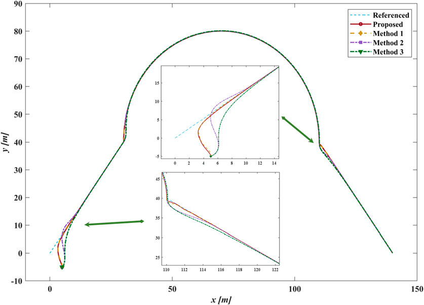
Figure 8. The path following results of different methods in case I.
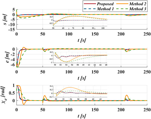
Figure 9. The following errors of different methods in case I.

Figure 10. The control moments of yaw
4.2 Case II
Case II uses the sinusoidal desired path, which is
Figure 11 demonstrates the proposed method applied under different initial positions. The GLOS guidance efficiently directs the vehicle regardless of the initial cross-track error distance
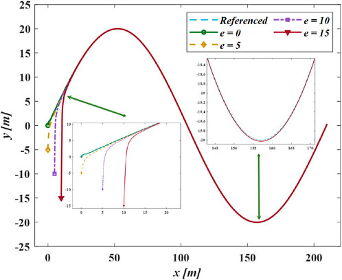
Figure 11. The following results of different position in case II.
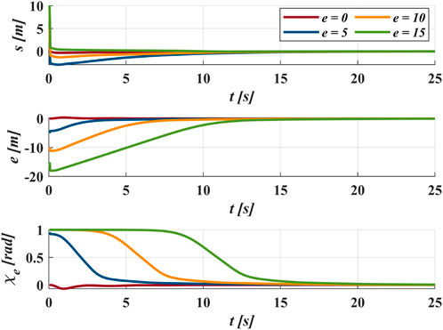
Figure 12. The following errors of different position in case II.
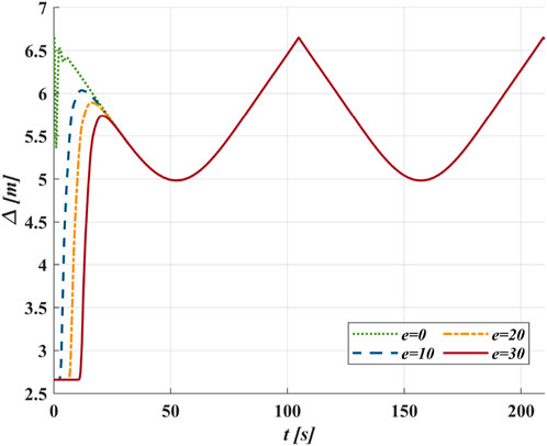
Figure 13. The change of
5 Conclusion
The guidance layer and control layer enhance the GNC system capabilities of marine vehicles. This paper presents a balanced approach, integrating guidance and control law calculations, to boost the GNC system’s robustness and adaptability, instead of merely optimizing the control law. To overcome the fixed look-ahead distance limitation, a novel GLOS guidance law is proposed. It can adaptively adjust according to the cross-track error and the curvature of nearby points, enabling the marine vehicles to handle various compounded paths. This law outperforms traditional LOS guidance laws in several aspects. For the control law, an improved exponential switching law based on the ISMC method stabilizes the yaw’s virtual angular velocity, featuring rapid convergence, anti-disturbance, and chatter suppression. The Lyapunov stability theorem verifies the global asymptotic stability of the designed system. Simulation results confirm the robustness and adaptability of these proposed schemes.
Future work will focus on verifying the proposed methods through actual tests using various vessels (e.g., AUVs and USVs), with validation conducted on these platforms.
Data availability statement
The original contributions presented in the study are included in the article/supplementary material, further inquiries can be directed to the corresponding authors.
Author contributions
CY: Project administration, Conceptualization, Writing – original draft, Software. CS: Funding acquisition, Resources, Writing – review and editing. ZZ: Conceptualization, Writing – original draft, Software, Methodology. BL: Writing – review and editing, Formal analysis, Resources. YC: Writing – review and editing, Funding acquisition. JM: Visualization, Methodology, Writing – review and editing, Supervision.
Funding
The author(s) declare that financial support was received for the research and/or publication of this article. This research has been supported by the National Key Laboratory on Ship Vibration and Noise Foundation (Nos JCKY2024207C105, 6142204240306).
Acknowledgments
We acknowledge the facilities and technical assistance of the National Natural Science Foundation of China.
Conflict of interest
The authors declare that the research was conducted in the absence of any commercial or financial relationships that could be construed as a potential conflict of interest.
Generative AI statement
The author(s) declare that no Generative AI was used in the creation of this manuscript.
Publisher’s note
All claims expressed in this article are solely those of the authors and do not necessarily represent those of their affiliated organizations, or those of the publisher, the editors and the reviewers. Any product that may be evaluated in this article, or claim that may be made by its manufacturer, is not guaranteed or endorsed by the publisher.
References
Borhaug, E., Pavlov, A., and Pettersen, K. Y. (2008). “Integral los control for path following of underactuated marine surface vessels in the presence of constant ocean currents,” in 2008 47th IEEE conference on decision and control (IEEE), 4984–4991.
Breivik, M., and Fossen, T. I. (2005a). “Guidance-based path following for autonomous underwater vehicles,” in Proceedings of oceans 2005 MTS/IEEE (ieee), 2807–2814.
Breivik, M., and Fossen, T. I. (2005b). “Principles of guidance-based path following in 2d and 3d,” in Proceedings of the 44th IEEE Conference on Decision and control (IEEE), 627–634.
Ding, S., Mannan, M., and Poo, A. N. (2004). Oriented bounding box and octree based global interference detection in 5-axis machining of free-form surfaces. Computer-Aided Des. 36, 1281–1294. doi:10.1016/s0010-4485(03)00109-x
Elmokadem, T., Zribi, M., and Youcef-Toumi, K. (2017). Terminal sliding mode control for the trajectory tracking of underactuated autonomous underwater vehicles. Ocean. Eng. 129, 613–625. doi:10.1016/j.oceaneng.2016.10.032
Encarnacao, P., and Pascoal, A. (2000). “3d path following for autonomous underwater vehicle,”, 3. IEEE, 2977–2982. doi:10.1109/cdc.2000.914272Proc. 39th IEEE Conf. Decis. control cat. No. 00CH37187
Fossen, T. I., and Lekkas, A. M. (2017). Direct and indirect adaptive integral line-of-sight path-following controllers for marine craft exposed to ocean currents. Int. J. Adapt. control signal Process. 31, 445–463. doi:10.1002/acs.2550
Fossen, T. I., and Pettersen, K. Y. (2014). On uniform semiglobal exponential stability (usges) of proportional line-of-sight guidance laws. Automatica 50, 2912–2917. doi:10.1016/j.automatica.2014.10.018
Fossen, T. I., Pettersen, K. Y., and Galeazzi, R. (2014). Line-of-sight path following for dubins paths with adaptive sideslip compensation of drift forces. IEEE Trans. Control Syst. Technol. 23, 820–827. doi:10.1109/tcst.2014.2338354
Han, P., Liu, Z., Zhou, Z., Ban, L., and Hao, L. (2018). Path tracking control algorithm based on los method for surface self-propulsion vessel. Appl. Sci. Technol. 45, 66–70. doi:10.11991/yykj.201706005
Heshmati-Alamdari, S., Nikou, A., and Dimarogonas, D. V. (2020). Robust trajectory tracking control for underactuated autonomous underwater vehicles in uncertain environments. IEEE Trans. Automation Sci. Eng. 18, 1288–1301. doi:10.1109/tase.2020.3001183
Kim, E., Fan, S., Bose, N., and Nguyen, H. (2021). Current estimation and path following for an autonomous underwater vehicle (auv) by using a high-gain observer based on an auv dynamic model. Int. J. Control, Automation Syst. 19, 478–490. doi:10.1007/s12555-019-0673-5
Lei, Q., and Zhang, W. (2017). Adaptive non-singular integral terminal sliding mode tracking control for autonomous underwater vehicles. IET Control Theory & Appl. 11, 1293–1306. doi:10.1049/iet-cta.2017.0016
Liu, T., Dong, Z., Du, H., Song, L., and Mao, Y. (2017). Path following control of the underactuated usv based on the improved line-of-sight guidance algorithm. Pol. Marit. Res. 24, 3–11. doi:10.1515/pomr-2017-0001
Ma, D., Chen, X., Ma, W., Zheng, H., and Qu, F. (2023). Neural network model-based reinforcement learning control for auv 3-d path following. IEEE Trans. Intelligent Veh. 9, 893–904. doi:10.1109/tiv.2023.3282681
Miao, J., Wang, S., Tomovic, M. M., and Zhao, Z. (2017). Compound line-of-sight nonlinear path following control of underactuated marine vehicles exposed to wind, waves, and ocean currents. Nonlinear Dyn. 89, 2441–2459. doi:10.1007/s11071-017-3596-9
Mu, D., Wang, G., Fan, Y., Bai, Y., and Zhao, Y. (2018). Fuzzy-based optimal adaptive line-of-sight path following for underactuated unmanned surface vehicle with uncertainties and time-varying disturbances. Math. Problems Eng. 2018, 1–12. doi:10.1155/2018/7512606
Patre, B., Londhe, P., Waghmare, L., and Mohan, S. (2018). Disturbance estimator based non-singular fast fuzzy terminal sliding mode control of an autonomous underwater vehicle. Ocean. Eng. 159, 372–387. doi:10.1016/j.oceaneng.2018.03.082
Prestero, T. T. J. (2001). Verification of a six-degree of freedom simulation model for the REMUS autonomous underwater vehicle. Cambridge, MA: Ph.D. thesis, Massachusetts institute of technology.
Qiao, L., and Zhang, W. (2019). Trajectory tracking control of auvs via adaptive fast nonsingular integral terminal sliding mode control. IEEE Trans. Industrial Inf. 16, 1248–1258. doi:10.1109/tii.2019.2949007
Reis, M. F., Jain, R. P., Aguiar, A. P., and de Sousa, J. B. (2019). Robust moving path following control for robotic vehicles: theory and experiments. IEEE Robotics Automation Lett. 4, 3192–3199. doi:10.1109/lra.2019.2925733
Rong, S., and Xu, Y. (2022). Motion parameter estimation of auv based on underwater acoustic Doppler frequency measured by single hydrophone. Front. Mar. Sci. 9, 1019385. doi:10.3389/fmars.2022.1019385
Roy, S., Baldi, S., and Fridman, L. M. (2020). On adaptive sliding mode control without a priori bounded uncertainty. Automatica 111, 108650. doi:10.1016/j.automatica.2019.108650
Song, S., Liu, Z., and Wang, Z. (2025). Anti-disturbance tracking control of rigid spacecraft attitude systems with saturation and asymmetric constraints. IEEE Trans. Aerosp. Electron. Syst., 1–14. doi:10.1109/taes.2025.3562840
Song, S., Liu, Z., Yuan, S., and Wang, Z. (2024a). Cascaded extended state observers-based fixed-time line-of-sight path following control for unmanned surface vessels with disturbances and saturation. IEEE Trans. Veh. Technol. 73, 7733–7747. doi:10.1109/tvt.2024.3357731
Song, S., Liu, Z., Yuan, S., Wang, Z., and Wang, T. (2024b). A finite-time path following scheme of unmanned surface vessels with an optimization strategy. ISA Trans. 146, 61–74. doi:10.1016/j.isatra.2024.01.016
Tutsoy, O., and Barkana, D. E. (2021). Model free adaptive control of the under-actuated robot manipulator with the chaotic dynamics. ISA Trans. 118, 106–115. doi:10.1016/j.isatra.2021.02.006
Wang, C., Cheng, C., Yang, D., Pan, G., and Zhang, F. (2023). Auv planning and calibration method considering concealment in uncertain environments. Front. Mar. Sci. 10. doi:10.3389/fmars.2023.1228306
Wang, D., He, B., Shen, Y., Li, G., and Chen, G. (2022). A modified alos method of path tracking for auvs with reinforcement learning accelerated by dynamic data-driven auv model. J. Intelligent & Robotic Syst. 104, 49–23. doi:10.1007/s10846-021-01504-0
Wang, Z., Wang, Y., Sun, Y., and Qin, H. (2024). Fixed-time dynamic event-triggered three-dimensional formation control for multi-auv system with disturbance observer. Ocean. Eng. 308, 118165. doi:10.1016/j.oceaneng.2024.118165
Xia, Y., Xu, K., Huang, Z., Wang, W., Xu, G., and Li, Y. (2022). Adaptive energy-efficient tracking control of a x rudder auv with actuator dynamics and rolling restriction. Appl. Ocean Res. 118, 102994. doi:10.1016/j.apor.2021.102994
Xiang, X., Lapierre, L., and Jouvencel, B. (2015). Smooth transition of auv motion control: from fully-actuated to under-actuated configuration. Robotics Aut. Syst. 67, 14–22. doi:10.1016/j.robot.2014.09.024
Xiang, X., Yu, C., and Zhang, Q. (2017). Robust fuzzy 3d path following for autonomous underwater vehicle subject to uncertainties. Comput. & Operations Res. 84, 165–177. doi:10.1016/j.cor.2016.09.017
Xu, H., and Pan, J. (2022). Auv motion planning in uncertain flow fields using bayes adaptive mdps. IEEE Robotics Automation Lett. 7, 5575–5582. doi:10.1109/lra.2022.3157543
Yu, C., Liu, C., Xiang, X., Zeng, Z., Wei, Z., and Lian, L. (2020). Line-of-sight guided time delay control for three-dimensional coupled path following of underactuated underwater vehicles with roll dynamics. Ocean. Eng. 207, 107410. doi:10.1016/j.oceaneng.2020.107410
Yu, C., Xiang, X., Wilson, P. A., and Zhang, Q. (2019). Guidance-error-based robust fuzzy adaptive control for bottom following of a flight-style auv with saturated actuator dynamics. IEEE Trans. Cybern. 50, 1887–1899. doi:10.1109/tcyb.2018.2890582
Yuan, C., Shuai, C., Fang, Y., and Ma, J. (2022). Decoupled planes’ non-singular adaptive integral terminal sliding mode trajectory tracking control for x-rudder auvs under time-varying unknown disturbances. J. Mar. Sci. Eng. 10, 1408. doi:10.3390/jmse10101408
Keywords: guidance law, line-of-sigh, path following, sliding mode control, marine vehicles, global asymptotic stability
Citation: Yuan C, Shuai C, Zhang Z, Li B, Cheng Y and Ma J (2025) Geometric line-of-sight guidance law with exponential switching sliding mode control for marine vehicles’ path following. Front. Robot. AI 12:1598982. doi: 10.3389/frobt.2025.1598982
Received: 24 March 2025; Accepted: 04 June 2025;
Published: 23 June 2025.
Edited by:
Shaoming He, Beijing Institute of Technology, ChinaReviewed by:
Önder Tutsoy, Adana Science and Technology University, TürkiyeZhilin Liu, Harbin Engineering University, China
Copyright © 2025 Yuan, Shuai, Zhang, Li, Cheng and Ma. This is an open-access article distributed under the terms of the Creative Commons Attribution License (CC BY). The use, distribution or reproduction in other forums is permitted, provided the original author(s) and the copyright owner(s) are credited and that the original publication in this journal is cited, in accordance with accepted academic practice. No use, distribution or reproduction is permitted which does not comply with these terms.
*Correspondence: Chengren Yuan, eWNyNDk3NTM5NzY0QGdtYWlsLmNvbQ==; Zhanshuo Zhang, MTU4MjcxMzkwMjRAMTYzLmNvbQ==