 Erik Braudeau
 Gaghik Hovhannissian
 Amjad T. Assi
 Rabi H. Mohtar
- 1Qatar Environment and Energy Research Institute, Qatar Foundation, Doha, Qatar
- 2Pédologie Hydrostructurale, Institut de Recherche pour le Développement France Nord, Institut de Recherche Pour le Développement, Bondy, France
- 3Unité Mixte de Recherche 242, Institut d'Ecologie et des Sciences de l'Environnement de Paris, Institut de Recherche pour le Développement France Nord, Institut de Recherche Pour le Développement, Bondy, France
- 4Biological and Agricultural Engineering Department, Texas A&M University, College Station, TX, USA
- 5Biological and Agricultural Engineering and Zachry Departments of Civil Engineering, Texas A&M University, College Station, TX, USA
The pressure plate method is a standard method for measuring the pF curves, also called soil water retention curves, in a large soil moisture range from saturation to a dry state corresponding to an applied pressure of near 1500 kPa. However, the pressure plate can only provide discrete water retention curves represented by a dozen measured points. In contrast, the measurement of the soil water retention curves by tensiometer is direct and continuous, but limited to the range of the tensiometer reading: from saturation to near 70–80 kPa. The two methods stem from two very different concepts of measurement and the compatibility of both methods has never been demonstrated. The recently established thermodynamic formulation of the pedostructure water retention curve, will allow the compatibility of the two curves to be studied, both theoretically and experimentally. This constitutes the object of the present article. We found that the pressure plate method provides accurate measurement points of the pedostructure water retention curve h(W), conceptually the same as that accurately measured by the tensiometer. However, contrarily to what is usually thought, h is not equal to the applied air pressure on the sample, but rather, is proportional to its logarithm, in agreement with the thermodynamic theory developed in the article. The pF curve and soil water retention curve, as well as their methods of measurement are unified in a same physical theory. It is the theory of the soil medium organization (pedostructure) and its interaction with water. We show also how the hydrostructural parameters of the theoretical curve equation can be estimated from any measured curve, whatever the method of measurement. An application example using published pF curves is given.
Introduction
There are numerous parametric equations for simulating the soil water retention curve, representing the relationship between the water content and the matric suction of a soil medium. This is usually expressed as a plot of volumetric water content (m3/m3) vs. suction (kPa) (Leong and Rahardjo, 1997). The proposed equations are empirical or semi-empirical (El-kadi, 1985; Leij et al., 1997), but are of great importance in soil water modeling where a retention function is needed to simulate water transport in the soil medium using the Richards' equation (Tietje and Tapkenhinrichs, 1993). Today, the most commonly used equations are those of van Genuchten (1980), Campbell (1974) and Brooks and Corey (1964), not an exhaustive list, which shows only that the exact physical equation, if it exists, is not known. Moreover, several names and units were given to the retention energy (matric potential, soil water tension, soil water suction, soil water retention, pressure head, and water potential) depending on the point of view of the scientific discipline using this important state variable in its physical models or experiments. It is generally known that the soil water retention phenomenon (water held in soil by retention forces) is related to the water potential in the soil matric—but how, exactly? How do we define the water potential in a natural medium (biological cell, soil medium) whose water content is changing? To answer such questions, we have to go back to the water thermodynamics in the natural medium.
According to “A Dictionary of Biology” (2004), the definition of the water potential in biological sciences is the following: “Symbol ψ. The difference between the chemical potential of the water μw in a biological system and the chemical potential of pure water at the same temperature and pressure, …. In soils and other extracellular systems, another factor, called matric potential, can contribute significantly to water potential.” This matric potential symbolized by “ψm” is a component of water potential due to the adhesion of water molecules to non-dissolved structures of the system, i.e., the matrix, such as plasma membranes or soil particles. It is always negative and it is significant only outside living cells in relatively dry systems, for example soils, where much of the water is tightly bound to soil particles.”
The definition of the water potential in soil water thermodynamics is almost the same: “In the soil physics literature, the chemical potential of soil water, μw, when referenced against the value of , is called the water potential and is given the symbol ψw” (Sposito, 1981, p. 193). The difference between both definitions of water potential lies in the definition of , which is the chemical potential of pure water at standard temperature (25°C) and pressure (1 atm).
As for the matric potential ψm, it is defined by Sposito (1981, p. 197) as a component of ψw responding to the equation dψm = (∂μw/∂W)T,P,PadW where W is the gravimetric water content (kgwater). “This potential component represents the effect of the changes in the water content, an effect usually attributes to the presence of the solid portion of a soil-water system. This equation also includes the effect of dissolved solid components of the soil water system on μw.” According to this definition, Braudeau et al. (2014) showed that the matric potential (ψm), measured by the tensiometer on unconfined soil samples at constant T and P, is in fact equals the chemical potential of soil water μw, when referenced against the value of μwsat. This value represents the water chemical potential of the soil medium at saturation, such that:
For those authors, the matric potential governs the local water movement in the soil medium linked to a local variation in water content and is due to the thermodynamic interaction between the liquid phase of water and the surface charges of the clay particles. The arrangement of these particles with other soil particles (silt, sand) makes the aggregated structure of the soil medium, namely the pedostructure.
The matric potential (ψm), as the soil water potential (ψw) of which it is a component, is always ≤0 and is expressed in unit of specific energy: Joule per kg of water (J ). “Quite often equivalent units are employed in place of the SI units. For example, the quotient μw/Mw, where Mw is the mole weight of water, is called the ‘molar water potential’ (joules per mole); the product μw where is the mass density of bulk liquid water, is called the ‘soil water pressure’ (J m−3 = Nm−2), and the quotient μw/g, where g is the gravitational acceleration, is called the ‘soil water head’ (J kg−1 m−1 s2 = m)” (Sposito, 1981, p. 194).
Agronomists and hydro-pedologists generally prefer to use units of pressure (Pa, positive) or of water head (m, negative) for the same notion of matric potential, using the symbol h. In this study, h will be expressed in terms of retention (or suction) pressure and will be the negative product of ψm and in kgwdm−3, such as:
h is positive or null and expressed in kPa. The curve h (W) will be called the “soil water retention curve” or, more precisely, the “pedostructure water retention curve” after Braudeau et al. (2014) who established its theoretical equation. Its thermodynamic formulation was established as a state equation depending on W (at T and P ambient and constant) and whose parameters are characteristics of the structural organization of the soil medium and its mineralogy. A methodology for measuring accurately these parameters was proposed based on the use of tensiometers (Assi et al., 2014). The advantage of having a unique thermodynamic formulation for the soil water retention curve, rather than a non-physically based equations (El-kadi, 1985; Leij et al., 1997), is that, despite the limited range of measurement of tensiometers (0–80 kP), this range can be considered as sufficient to determine the parameters which are theoretically valuable for the entire curve or, at least, until the micro air entry point (Braudeau et al., 2014), i.e., largely beyond 80 kPa.
The problem stays in the method of measurement of these characteristic curves: the measurement of the soil water retention curves by tensiometer is direct and continuous but it is limited to the range of the tensiometer reading. In contrast, the curves obtained using the pressure plate method (Richards, 1948) are built by a dozen (or more) measured points but can cover a larger soil moisture range, from saturation to a water retention of near 1500 kPa. So, the two different methods are not covering the same range of soil moisture, nor do they have the same accuracy (Schelle et al., 2013). The junction between these ranges remains uncertain; moreover, inconsistent results were also noted comparing pressure plate with dew point method (Cresswell et al., 2008; Bittelli and Flury, 2009; Solone et al., 2012). In fact, not only is the accuracy of the pressure plate apparatus undefined, but its principle of measurement is also questionable as soon as soils are considered non-rigid (Sposito, 1981, p. 200).
The goal of this article is to integrate the soil water retention curve measured using the pressure plate apparatus into the unified theoretical framework proposed by Braudeau and Mohtar (2014) where, in particular, the physical equations of the hydrostructural functioning of the pedostructure are well established. This theoretical framework has to be used for interpreting the different methods of measurement of the soil water properties in order to compare the measured moisture characteristic curves with their theoretical equations. Thus, the pressure plate method (Richards, 1948) will be: (1) reconsidered from the thermodynamic point of view of this theoretical framework in order to theoretically formulate the water retention curve actually measured by this method; and (2) compared with the theoretical equation curve, accurately measured by the tensiometer.
Theory
Physical Equation of the Pedostructure Water Retention Curve h(W)
Braudeau and Mohtar (2009) showed that any physical equation of the soil structure and soil water interactions cannot be found without changing the paradigm used for the soil medium characterization and modeling. This shift in paradigm must allow for considering the internal and multi scaled organization of the soil structure in the soil water physics. The concept of pedostructure (Braudeau et al., 2004) is at the basis of the new proposed paradigm. It represents and defines the first level of organization of the soil medium in a soil horizon, as an assembly of primary peds. These peds are composed of a clayey mixture (S-matrix: Brewer, 1964) and act like saturated clay pastes at high water content.
The Structural Representative Elementary Volume (SREV) concept and the associated terminology for describing the pedostructure state variables (Table 1) were then applied to the thermodynamic theory of water in soil presented by Sposito (1981). The particularity of the SREV variables is that all extensive variables describing the different levels of organization of a given volume of soil structure (SREV) sampled (cut) in the soil medium is reported to the mass Ms of the structure contained in this volume. Therefore, the thermodynamic functions, which are all extensive variables (U, G, H), were rewritten according to the SREV concept and using the SREV variables, i.e., extensive variables reported to the structural mass Ms (Braudeau and Mohtar, 2009; Braudeau et al., 2014). Except for the water content, symbol W or w, the other SREV variables will be distinguished from the corresponding extensive variable by a single bar above the variable, like U, Gw, Sw, Vw, …, meaning U/Ms, Gw/Ms, Sw/Ms, Vw/Ms, …, and not the derivative dx/dms that the single bar means in many articles. Thus, the Gibbs-Duhem equation applied to the component i of the phase a, according to Sposito (1981, p. 15), can be rewritten in the SREV paradigm, such that:
where Sα,Vα, and Wα are the massic entropy, massic volume and water content of component i of the phase a, all reported to the pedostructure mass of the sample Ms.
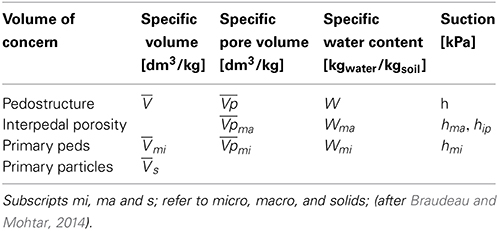
Table 1. Pedostructure state variables.
Using this terminology, it could be shown that the pedostructure water retention h (in kPa) must be defined as:
where μma and μmi are the chemical potentials of the water in the pore spaces inter and intra primary peds, corresponding to the water contents Wma and Wmi; while μmasat and μmisat correspond to Wmasat and Wmisat. We should note that μmasat = , the chemical potential of the free water, at ambient temperature and atmospheric pressure, while μmisat < μmasat = in all cases.
Showing that the pedostructural Gibbs free energy (accounted negatively) for each water component of the liquid phase: Gwmi = Wmiμmi and Gwma = Wmaμma, remains constant after any change in water content. Braudeau et al. (2014) established the physical equation of h(W), the soil water retention curve, for the general case of the pedostructure (structured soil medium).
where, hmi is the water retention inside the primary peds (kPa), hma is the water retention outside the primary peds (kPa); is the bulk density of water [1 kgwater dm−3], Emi and Ema [J ] are the specific potential energies inside the primary peds and outside of the primary peds. They result from the surface charges of the clay particles and are equal to −Gwmi and −Gwma, respectively. and are the micro and macropore water contents at equilibrium when hmi = hma = h. Their equations, deduced from (4) and (5), are:
and
where, A is a constant representing the difference of chemical potentials of the two types of water (Wma and Wmi) at saturation:
and WmiSat and WmaSat are the micro and macro water content at saturation such that:
The pF Curves
The pressure plate apparatus is widely used in pedology and agronomy to get what is named the pF curve: log of the suction pressure, expressed in cm of water height, vs. the water content W. Fully saturated soil (or clay paste) samples are put in contact with a saturated porous plate and the whole is submitted to a given pressure P of the air introduced in the pressure chamber. The other side of the porous plate is open to the atmospheric pressure. The samples water content decreases under this pressure, the water crossing through the porous plate, until a thermodynamic equilibrium is reached. The pF curve is the air pressure applied on the sample (usually the log of this pressure in cm of water) vs. the corresponding water content (kg/kg) of the sample at equilibrium. The question is the following: is this pressure equivalent to the difference of the water chemical potentials as stated in Equation (2)?
Under the pressure (atmospheric pressure plus applied pressure: Pa + Π) and when the transfer of water has ceased, the water content in the sample is W = ρwVw (remembering that Vw = Vwater/Ms and W = Mwater/Ms, Table 1) and the water chemical potentials (μw) of the liquid and gas phases of the pedostructure and the pressure chamber, is equal to the potential of free water, , which is the water chemical potential at the other side of the porous plate submitted to the atmospheric pressure. Thus, when the pressure is returned to Pa and the chamber is opened to the air without any change in water content of the sample (W), the pedostructure water potential decreased from (under Pa + Π) to its equilibrium value, μw, at ambient T and Pa. The water retention (or suction) h defined by Equation (4) passes from the value 0 to h = −(μwma − ) under the atmospheric pressure Pa.
Consider now the Gibbs-Duhem equation Equation (3) is applied to the external layer of the pedostructure liquid phase at the liquid-gas interface (variables with subscript lg). At this interface, the state variables can be defined such that: Wlg = ∆Wma, Swlg = ∆Swma, and Vwlg = ∆Vwma, thus, the equation can be written such that:
Dividing Equation (10) by Wlg gives a relationship between the specific entropy Ŝwlg = Swlg/Wlg (in JK−1kg−1 of water) and the specific volume wlg = Vwlg/Wlg (in dm3kg−1 of water if P in kPa) of the liquid interface in contact with air in the pedostructure (soil) sample:
On the other hand, the Gibbs-Duhem equation related to the water component of the gaseous phase of the pedostructure (variables with subscript g) at equilibrium with the air in the pressure chamber can also be written such that:
where Swg, Vwg, and Wg are the entropy, the partial volume and the mass of the water molecules of all the gaseous phase (in the pedostructure and in the pressure chamber) reported to Ms. Then, dividing Equation (12) by Wg gives:
where Ŝwg = Swg/Wg, the specific entropy of the water vapor, and wg = Vwg/Wg, the specific partial volume of the water vapor in the air. Assuming that all the components of the gaseous phase have behavior of perfect gas (subscript g) and, according to the state equation of ideal gasses:
where R (Jmole−1K−1) is the constant of perfect gasses, Mw is the molar mass of water, Mg the molar mass of gas, and VA is the volume of 1 mole of ideal gas at pressure P and temperature T.
Since dμwma = dμwg at equilibrium of the two phases in contact (exchange of molecules of water) subtracting Equation (11) from Equation (13) gives:
Thus, in a transformation at T constant:
meaning that wlg stays equal to wg in this transformation and, according to Equation (14),
Integrating Equations (11) and (13) from the hydrostructural state of the sample under (Pa + Π) to the state at Pa in the pressure apparatus, keeping T and W constant and replacing wlg and wg by their expression given by Equation (17), provides the same formulation of h Equation (20):
∆μw is numerically equal to ψm since and μw are the values of the chemical water potential at T and P constant (laboratory conditions). Thus, a pressure of (Pa + Π) in the pressure plate apparatus leads, at equilibrium, to a water content W corresponding to the water retention h given by Equation (20), analog to the water retention measured by the tensiometer under the atmospheric pressure.
Replacing heq by its equation in terms of or Equation (5) leads to the relationship between the applied air pressure in the chamber and the two pedostructural water contents Wmi and Wma, such that:
where and are calculated using Equations (6a) and (6b).
The difference between the “lg” and “g” phases stays only in the fact that the fraction of water molecules is 1 in the liquid-gas interface while this fraction is Nwg/Ng = pw/P in the gaseous phase of the sample and the pressure chamber; pw is the partial pressure of water vapor, Nw the number of water molecules and Ng the total number of gas molecules in the air phase. This means also that pw = P in the “lg” interface.
Materials and Methods
To validate the theory above we need to compare the two soil water retention curves obtained by the two methods using: the tensiometer (Braudeau et al., 2014) and the pressure plate apparatus (Richards, 1948). The tensiometric measurements were made on unconfined cylindrical soil samples reconstituted from 2 mm-sieved soil material and using the TypoSoil® apparatus according to the methodology described in Assi et al. (2014). The preparation of the sample, the measurement and the treatment of data to extract parameters of the water retention curve: Ema, Emi, WmiSat and WmaSat, of Equations (5) and (6) have been detailed in the article.
As for the pressure plate apparatus method, the obtained curves called “pF curves” represent generally the log of the applied air pressure, in hPa, vs. the corresponding water content in kg/kg, at equilibrium under this air pressure. In this classical method, the applied pressure is identified to the water retention h, contrary to what we have deduced here in the theory where h is proportional to the logarithm of the applied pressure. The samples put on the porous plate are constituted of 2 mm-thick slices cut from the cylindrical samples prepared for the TypoSoil® analysis (Assi et al., 2014). The slices (three replicates for the water content measurement at a given pressure) were put in a ring on the porous plate and saturated with water.
Two types of soil were tested; they are the same as those used in Braudeau et al. (2014) article: a soil sample of Versailles soil from France, and a soil sample of Rodah soil from Qatar. Their characteristics are given in Table 2.
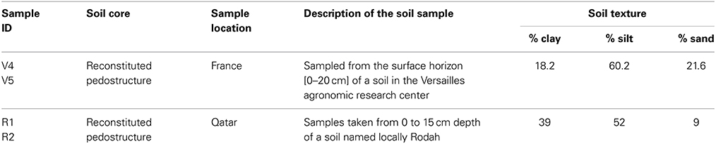
Table 2. General description of soil samples.
For each soil, two replicates of a pedostructure sample were prepared in cylinders of 5 cm diameter and height using the fine ground samples (aggregated soil material < 2 mm) stored in the laboratory. The two moisture characteristic curves, V(W) and h(W), were then measured using the TypoSoil® apparatus following the methodology mentioned above (Assi et al., 2014).
The pF curves for the two soils were measured using the pressure plate apparatus but at two different places and times, so the set of data making the curve (applied pressure and water content) is different in the two cases: For the Rodah soil, pressures applied (kPa) were: 80, 100, 150, 200, 400, 1000; using only one kind of porous plate: “15 bar,” and for the Versailles soil, pressures applied were: 1, 5, 10, 30, 50, 80, 100, 200 kPa, using a porous plate of “1 bar” for the low values of pressure and 5 bar for 100 and 200 kPa. A beaker of 50 cm3 of water was put on the 15 bar plate to saturate the air in the chamber and the waiting time to reach equilibrium was no more than 1 week.
These sets of applied pressures are converted into the water retention of the sample h (in kPa) corresponding to the water content reached at equilibrium under the applied pressure Π, using Equation (20) where R = 8.314 J mole−1 K−1, T = 294 K for Rodah and 298 K (for Versailles), Mw = 0.018 kg mole−1 and ρw = 1 kg dm−3. Practically, the relationships used for the correspondence between the applied pressure, Π, and the water retention at equilibrium is, for T = 294 K:
where h and Π are expressed in kPa.
Parameters of the pedostructural water retention curve (WSat, WmiSat, Emi, Ema) are then extracted from the measured water retention curve according to the methodology given in Braudeau et al. (2014) and detailed in Assi et al. (2014) by adjustment of the theoretical equation h(W) to the measured curve. All calculations were done in Excel sheets, using the Excel solver for optimization of adjustments of the measured curve by the theoretical one.
Results
Comparison of Water Retention Curves Obtained by the Two Methods
The pedostructural moisture characteristic curves (water retention curve, WRC, and shrinkage curve, ShC) of the two replicates of pedostructure prepared for each soil were measured using TypoSoil®. Then, the curves were fitted by their theoretical equations to obtain the corresponding hydrostructural parameters. The methodology of fitting is explained in Braudeau et al. (2014) for the kind of soil sample analyzed here (Figure 1), presenting a sigmoidal shape with a shrinkage phase due to the saturating interpedal water Wip at high value of W. The hydrostructural parameters of the water retention curve obtained from the optimization of the adjustment are given in Table 3.
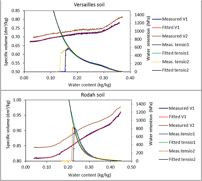
Figure 1. Pedostructural moisture characteristic curves of two replicates of a pedostructure sample of two soils. For each soil, the curves of the two replicates are represented: (i) The measured (blue points) and fitted (red) shrinkage curve (ShC), for replicate 1; (ii) The measured shrinkage curve (brown points) for replicate 2; (iii) The measured (blue points with line) and fitted (green) water retention curve (WRC); and (iiii) the measured (brown points with line) and fitted (black line) water retention curve for replicate 2.
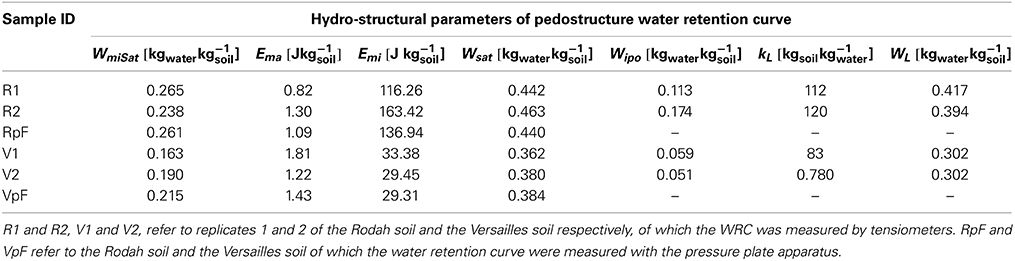
Table 3. Values of parameters of the pedostructural water retention curve for Rodah and Versailles soils.
The measured characteristic curves of the replicates are very close to each other (Figure 1), attesting the appropriate preparation procedures of the pedostructure samples and the accuracy of their characterization. The shrinkage curves are shifted only by a constant value of the specific volume and the water retention curves of the two replicates are almost superimposed in both cases, although the validity of measurement is limited to low values of suction (800 hPa for Rodah soil and 600 Pa for Versailles soil on Figure 1). As their physical equation is known (Equation 5) and assumed to be valid for the whole curve (at least up to air entry point in primary peds), and because parameters can be determined on the range measured by the tensiometer, the modeled water retention curves cover the whole range of water contents and can be compared to the results given by the pressure plate apparatus.
This comparison is presented in Figure 2 which shows for each soil the water retention curves: (i) measured with the pressure plate apparatus, (ii) modeled by fitting on the measured points of the pF curve, and (iii) modeled using parameters extracted from the tensiometric curve measured by TypoSoil®. The pressure plate measurement data are given in Table 4. We can see from Figure 2, the very good concordance of the curves coming from the two kinds of measurement. This confirms the validity of the relationship Equations (20) and (22) between the applied pressure Π and the corresponding matric (or pedostructural) water retention h.
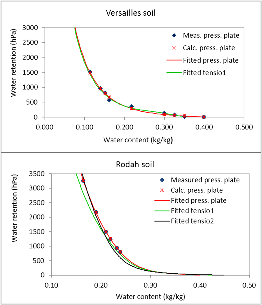
Figure 2. Three water retention curves for each soil. (i) Measured (dark-blue points) using the pressure plate apparatus, (ii) Fitted (red line and crosses) on these measured points using the theoretical equation of the curve and (iii) (green line and black line) fitted on the measured water retention curve using a tensiometer.
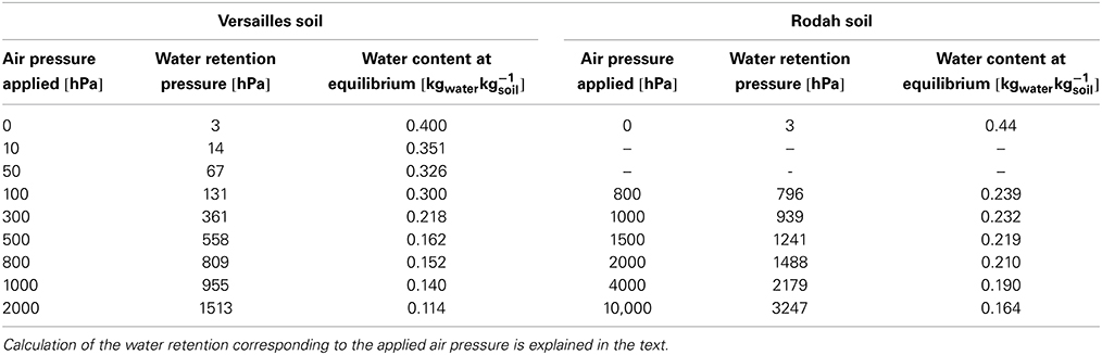
Table 4. Data of the pressure plate apparatus experiment for the measurement of the water retention curve (pF curve) of two soils.
Moreover, as it can be seen in Table 3, the fitting using the physical equation of the water retention curve on the points measured with the pressure plate apparatus, provides parameters (lines RpF and Vpf of Table 3) that are very close to those of the modeled curve coming from the tensiometer (lines R1, R2, V1, V2).
We can conclude from these results that the water retention curve can be accurately measured using the tensiometer as well as the pressure plate apparatus, provided that, in this last case, h has been calculated from Π using Equation (20). Accordingly, the four hydrostructural parameters of the water retention curve, namely: WSat, WmiSat, Emi, and Ema, characterizing the pedostructure, can be obtained from the one or the other method. However, the tensiometer method is faster and very accurate at low retention pressure (0–500 hPa). It should be preferred, in particular for the kind of soil like those selected here which presents an interpedal shrinkage phase parallel to the saturated line, at the beginning of the shrinkage curve, and for which two parameters more are needed: WL and kL (Braudeau et al., 2014). The shape of the retention curve in this part, near saturation, looks like the traditional curves with an air entry near saturation (at θw, similar to WL). These parameters make part of the set of soil characteristics required by the multiscale soil water model Kamel® (Braudeau and Mohtar, 2014) built in respect to the new paradigm of the hydrostructural Pedology. An example of treatment of pF curves according this new paradigm is given here after.
Application to pF Curves Found in Soil Data Bases
As an example of application, we used the data of water retention curves published on the web by the Center of Ecology and Hydrology (Blyth, 2011). The water retention curves (pF curves) were constructed as follows: “At each depth, two samples were collected. The samples were stood in a water bath until they reached an equilibrium (saturated) weight. The samples were then placed in (1) a sand bath, (2) a sand/kaolin bath, (3) pressure vessels set at a range of suctions in order to progressively dry out the samples. Water-release curves were constructed for each soil level.” Table 5 presents the water retention data re-arranged such that: (i) the set of the different pF values (1st column) given by the authors; these pF values are the currently assumed ones corresponding to the log of the water suction expressed in hPa or cm of water (2nd column); (ii) the method used for equilibrium of the sample under suction (methods 1 and 2) or under air pressure in the pressure plate apparatus (method 3); and (iii) the corresponding value of the water retention pressure h in hPa, equal to the suction pressure for the measurement methods (1) and (2) and calculated using Equation (20) for the pressure plate method (3).
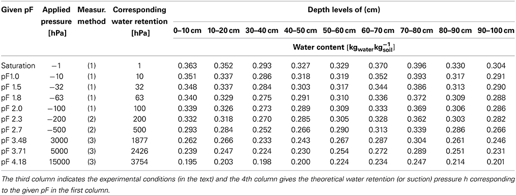
Table 5. Chimney Meadow (Church Field) soil water retention measurements (pF curves) data.
Four selected pedostructural water retention curves, among the nine listed in Table 5, are shown in Figure 3; the measured points are presented with their fitted theoretical curve. The corresponding parameters obtained from the fitting of the measured points are presented in Table 6 for the 9 samples. The high values of WmiSat relative to Wsat and of Emi relative to Ema indicate that the soil is clayey and has a small macro porosity (interpedal porosity).
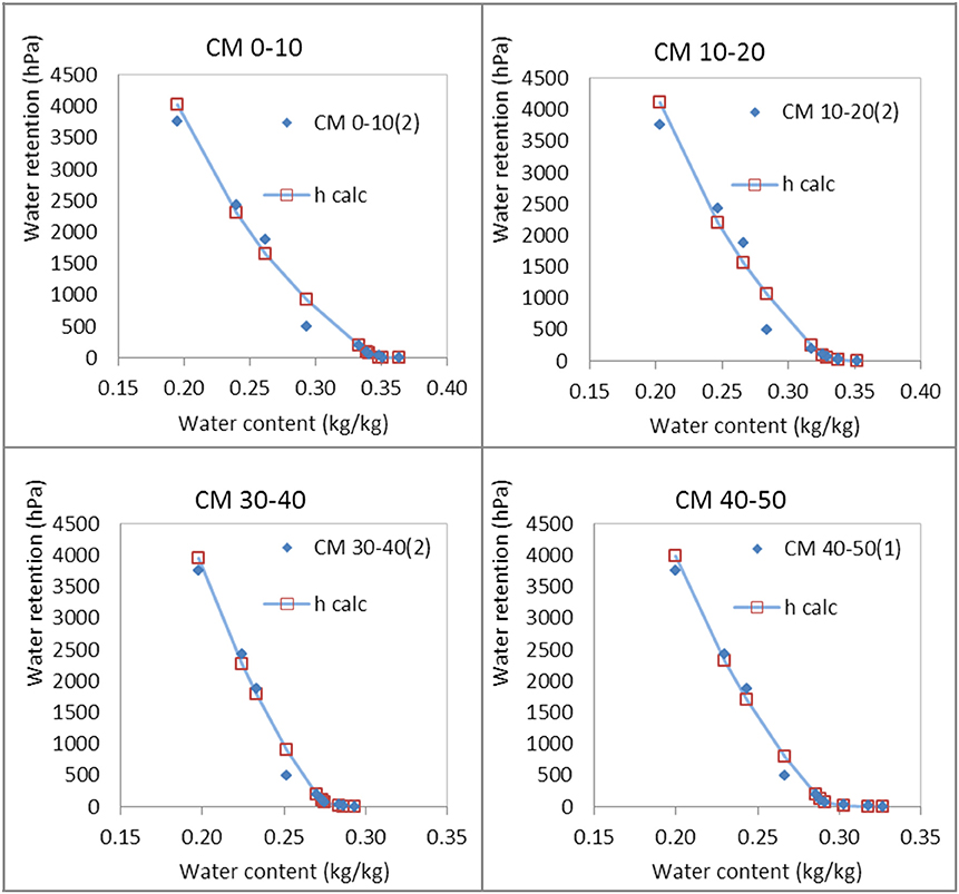
Figure 3. Pedostructural water retention curves of the four first depth levels of the Chimney Meadow (Church Field) soil, measured (blue points) and fitted with the theoretical equation (blue line and red squares).
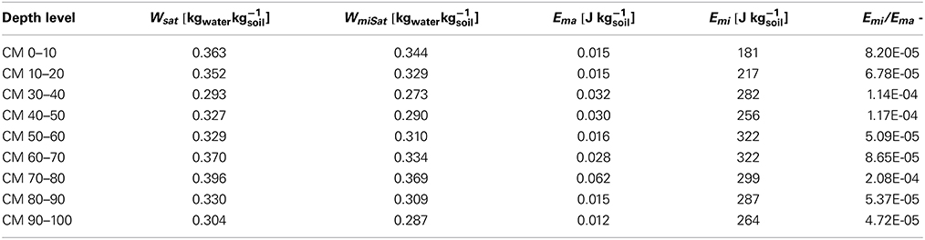
Table 6. Pedostructural water retention curve parameters obtained by fitting the corrected Chimney Meadow soil water retention curves with the theoretical equation.
The sets of four parameters characterizing each layer are not very different from each other. This is consistent with the description of the soil given in the report: “Church Field lies on a clay lens which overlies surrounding sand and gravel soils. Apart from the A and B horizons, the clay was found to be fairly homogenous down to the maximum depth of 1.1 m of the access pit.”
Discussion
Comparison with the Membrane Press Results of Low (1979) on Clay Pastes
Results show clearly that the relationship between the applied air pressure in the pressure plate apparatus and the pedostructure water retention pressure h(W), as it is measured by the tensiometer in the laboratory, is described by Equation (20). This leads to Equation (21) between the air pressure and the pedostructural macro and micro water contents at equilibrium and . This equation is similar to the empirical equation found by Low and Margheim (1979) between the applied pressure Π and the water content of the clay pastes in the membrane press apparatus and that Low (1979) expressed such as:
in which mc/mw is the mass ratio of water to montmorillonite, Π is the applied pressure, in units of atmosphere, “and α is a linear function of the specific surface area and cation exchange capacity.” This equation was obtained for clay pastes which has no structure, so we can identify mc/mw with 1/Wmi, so Equation (23) can be written as:
Comparing this equation to Equation (21), gives:
α = MwEmi/RT and = WmiSat, the maximum of absorbed water by the clay paste.
The water content Wma is negligible and concerns the layer of water at the surface of the clay paste in contact with the air. Therefore, Low's equation expresses, in fact, the following relationship between the applied pressure and the matric potential ψm of the clay paste:
where ψm = ∆μw = −h/ = −Emi(1/Wmi − 1/WmiSat), contrary to what Low (1979) was thinking, namely that Π could be identified to the swelling pressure (−ρw∆μw).
Water Vapor Pressure pw at the Surface of the Pedostructural Water
Equation (25) can be written as:
This means that, assuming the well-known relationship between μw − and the water vapor pressure pw at the surface of water in the pedostructure, Equation (25) can also be written such that:
this relationship compared to Equation (26) leads to:
where is the water vapor pressure over pure water at ambient T and P.
On the other hand, considering the external layer of the interface liquid-gas “lg,” where the partial pressure of water is pw = P (the pressure in the chamber), and taking into account Equation (17), we have the following equalities:
These equalities (29) could explain the assertion of Low (1980) who said that “Our evidence shows that every property of the interlayer water obeys the following general equation:
in which J represents any given property of the interlayer water, J° represents the value of this property for pure bulk water and b is a constant.” In fact, according to our results, we should have:
which, according to (29), leads to:
Thus, Equation (30) of Low (1980) could be explained by the direct relationship of any thermodynamic property J of the water at the surface of clays with the specific volume wlg of the water layer at the interface liquid-vapor which depends on the water content of the clay paste according to Equation (32).
Fundamentals of the Pedostructural Water Thermodynamics
The definition of the matric potential by Sposito (1981) as representing “the effect of changes in the water content” at T and P constant, is in total agreement with our results obtained here. The thermodynamic equation of the pedostructural water retention curve, which was validated only on the little validity range of tensiometers, is validated now on the larger range covered by the pressure plate method. It is obvious that the “matric potential” defined above and which is the potential of a mixture of soil particles, water and air, corresponds to the “pedostructural water potential,” the potential of the water contained in the pedostructure which is defined in the SREV paradigm as a thermodynamic system representing the soil medium at its first levels of organization: those of the primary peds and their assembly. It's why we could define two phases in the water phase of the soil matric: one (Wmi) embedded in the other (Wma), corresponding to the intra and inter- primary peds. Primary peds correspond to the first level of aggregation of clay particles. The thermodynamic law that we evidenced in our experiments and which is at the basis of the pedostructural water retention equation, is that the pedostructural Gibbs free energies (accounted negatively in Jkg−1 of solids) for each water component of the liquid phase, Gwmi and Gwma, defined as the products:
remain constant (equal respectively to −Emi and −Ema) against any change in water content.
This law is, for the pedostructural water liquid phase, of the same nature as the perfect gasses law for the gaseous phase. Any change in water content provokes a change in Wmi and Wma and simultaneously a change in μmi and μma such that their products stay constant according to Equation (34):
From this phenomenon (Gwmi and Gwma constant), we can deduce immediately the following fundamental equation:
leading to the Gibbs-Duhem equation for both phases, like Equation (3) for Wma above.
In conclusion, we can say that the matric potential as defined by Sposito (1981) is exactly the pedostructural water potential as defined by:
Divided by the negative value of the bulk water density (−), it has unit of pressure and can be called: water retention pressure (or matric suction pressure) h,
The pedostructural water potential ψm can also be expressed in water head (m) by dividing by the gravitational acceleration g.
The conversion between the different units is as follows: 1019 cm of water head = 1 bar = 1000 hPa = 100 kPa
Corrections to Make on the Retention Curves given by PTFs
Pedotransfer functions (PTFs) are widely used in soil water modeling to estimate the hydraulic characteristics of soils from simple soil characteristics, such as texture, organic matter content, etc. Tietje and Tapkenhinrichs (1993) “grouped PTFs into three categories: (i) estimate the water content at certain matric potentials; (ii) estimate soil water retention relation with a physical conceptual modeling approach, and (iii) estimate parameters of an algebraic retention function.” Corrections that should be done are only those concerning the retention pressures above 60 kPa that are yielded by PTFs of the first and third group. It would consist to calculate the corrected values of h using Equation (20) or (22) replacing Π by the value of h given by the PTF. For example, the retention function estimated by Saxton and Rawls (2006) between 1500 and 33 kPa, namely: ψ(1500−33) = Aθ)−B, where A and B are estimated such as: A = exp(ln(33) + Bln(θ33)) and B = [ln (1500) − lnθ(33)]/[ln(θ1500) − ln(θ33)]. We can just correct the parameter B by using ln(382) instead of ln(1500) in the formula and calculate ψ(1500−33) using the corrected parameters, or we can also let the parameters as they are and correct the retention pressure ψ(1500−33) by using Equation (22) such as (in kPa):
The proposed correction would be valuable in principle for all retention functions falling in the third category and currently used in soil-water models, like the very popular equation of van Genuchten (1980). In contrast, retention functions of the second category like the one proposed by Rieu and Sposito (1991) do not need this kind of correction above and are well working but only if parameters of the curve are accurately measured (Braudeau and Mohtar, 2004).
The correction brought to ψ(1500) seems enormous: passing from 1500 to 382 kPa. In fact, looking at Table 4, we can see that the corrections for the suction pressures generated by the pressure plate are negligible in the range 0–100 kPa, but then they are exponentially increased after 100 kPa This corresponds to the results of Solone et al. (2012), Bittelli and Flury (2009) and Cresswell et al. (2008) who worked on the adequacy of the pressure plate for determining the water retention curve: the measured total water potential using a thermocouple psychrometer was consistently less negative (wetter) than the expected matric potential of the sample (identified to the applied air pressure) after equilibrium in the pressure plate apparatus. The discrepancy between both measurements (dew point and pressure plate) appears at 100 kPa and increases strongly thereafter depending on the texture. However, they observed that the expected matric potential −1.5 MPa can be obtained, in certain conditions, for rigid soils (non-swelling soils, sandy soils). Our interpretation is that the matric potential sensu- stricto is the specific potential energy of the water surrounding the clay particles and so, in contact with their surface charges. The clay particles are never cemented between them: if there is no swelling of the matric, the matric potential that we want to measure does not exist and the sample is like a bundle of capillary tubes on which the air pressure acts like a piston to remove the water from the sample; it is not the thermodynamic equilibrium by which the matric potential is defined.
Conclusion
In order to theoretically formulate and unify the water retention curve measured by pressure plate and tensiometers, we have analyzed the measurement method of pF curves by the pressure plate apparatus based on the thermodynamic theory of the soil medium organization (Pedostructure-SREV concept). The same theoretical paradigm has been applied before only on the tensiometeric measurement range (0–80 hPa) for the water retention curve (Braudeau et al., 2014). In this paper, we were able then to compare the results given by both methods (tensiometer and pressure plate) with those given by the theoretical equations. The parameters used in these equations were extracted from the measured WRC by TypoSoil®. It was found that the pressure plate method provides in fact measured points of the characteristic retention curve h(W) of the soil sample, but after a certain calculation of h from the applied air pressure Π that has been established according to the theory. Besides the fact that the thermodynamic analysis of the pressure plate method has led to a thermodynamic definition of what quantity is actually measured by this method, explaining old results obtained on clays pastes, this work has several significant practical implications in soil science, as follows:
– What is called matric water potential or matric potential (ψm, negative), as was well defined by Sposito (1981) in the REV paradigm, corresponds quantitatively to the “pedostructure water potential” defined in the SREV paradigm. Other terms can be encountered in soil science and agro environmental modeling, but all refer to this physical quantity (ψm) which can be expressed in units of pressure (−ψm) (then qualified by the term “pressure,” positively valued) or expressed in units of length and qualified by the term head (i.e., matric pressure head, negative).
– The water retention curve measured in laboratory using tensiometer is very precise but only valid within a limited range of water retention, from 0 at saturation to near 60 kPa; our results showed that it can be extended to high retention pressure (at least 1500 kPa) using the modeled curve of which the hydrostructural characteristic parameters have been obtained from tensiometric curves, using the valid range of measurement. This was confirmed by the points of the water retention curve obtained at high pressure by the pressure plate method on the same soil sample.
– We can now reconsider the “pF curves” stored in soil data bases and transform them into the correct pedostructure water retention curves that are characteristic of the soil horizon which was sampled. We showed how the four hydrostructural parameters of these curves can be easily extracted by fitting with the thermodynamically-based equation of the curve. These parameters are physically-based and so are universal and valuable for all type of soils, opening the way for building a hydro-functional typology of the pedostructures. They represent the entire soil water retention curve that is needed by all models of soil water dynamics.
Conflict of Interest Statement
The authors declare that the research was conducted in the absence of any commercial or financial relationships that could be construed as a potential conflict of interest.
Acknowledgments
We acknowledge the CEH (Center for Ecology and Hydrology, UK) for having supplied the soil water release dataset (Chimney Meadow pF curves) that we used in this paper. We wish also to thank the following scientists for their help in this work: Alain Betsogo Atoua (Master IRD), Estelle Hedri (Valorhiz), Josh Accola (Master QEERI), and Marc Lointier, (IRD).
References
A Dictionary of Biology. (2004). Water Potential. Available online at: http://www.encyclopedia.com/doc/1O6-waterpotential.html [Accessed May 30, 2014]
Assi, A. T., Accola, J., Hovhannissian, G., Mohtar, R. H., and Braudeau, E. F. (2014). Physics of the soil medium organization part2: pedostructure characterization through measurement and modeling of the soil moisture characteristic curves. Front. Environ. Sci. 2:5. doi: 10.3389/fenvs.2014.00005
Bittelli, M., and Flury, M. (2009). Errors in water retention curves determined with pressure plate. Soil Sci. Soc. Am. J. 73, 1453–1460. doi: 10.2136/sssaj2008.0082
Blyth, K. (2011). Chimney Meadow (Church Field) Soil Water Retention Measurements (pF Curves). NERC-Environmental Information Data Centre. doi: 10.5285/59da8e86-04cc-4f46-a23c-65513d025326
Braudeau, E., Assi, A. T., Boukcim, H., and Mohtar, R. H. (2014). Physics of the soil medium organization part1: thermodynamic formulation of the pedostructure water retention and shrinkage curves. Front. Environ. Sci. 2:4. doi: 10.3389/fenvs.2014.00004
Braudeau, E., Frangi, J. P., and Mothar, R. H. (2004). Characterizing non-rigid dual porosity structured soil medium using its shrinkage curve. Soil Sci. Soc. Am. J. 68, 359–370. doi: 10.2136/sssaj2004.3590
Braudeau, E., and Mohtar, R. H. (2004). Water potential in non rigid unsaturated soil-water medium. Water Resour. Res. 40:14. doi: 10.1029/2004WR003119
Braudeau, E., and Mohtar, R. H. (2009). Modeling the soil system: bridging the gap between pedology and soil-water physics. Glob. Planet. Change J. 67, 51–61. doi: 10.1016/j.gloplacha.2008.12.002
Braudeau, E., and Mohtar, R. H. (2014). A framework for soil-water modeling using the pedostructure and structural representative elementary volume (SREV) concepts. Front. Environ. Sci. 2:24. doi: 10.3389/fenvs.2014.00024
Brooks, R. J., and Corey, A. T. (1964). Hydraulic Properties of Porous Media. Hydrol. Pap. 3. Fort Collins, CO: Colorado State University.
Campbell, G. S. (1974). A simple method for determining unsaturated conductivity from moisture retention data. Soil Sci. 117, 311–314. doi: 10.1097/00010694-197406000-00001
Cresswell, H. P., Green, T. W., and McKenzie, N. J. (2008). The adequacy of pressure plate apparatus for determining soil water retention. Soil Sci. Soc. Am. J. 72, 41–49. doi: 10.2136/sssaj2006.0182
El-kadi, A. I. (1985). On estimating the hydraulic properties of soil, Part 1: comparison between forms to estimate the soil- water characteristic function. Adv. Water Resour. 8, 136–147. doi: 10.1016/0309-1708(85)90054-5
Leij, F., Russell, W., and Lesch, S. M. (1997). Closed-form expressions for water retention and conductivity data. Ground Water 35, 848–858. doi: 10.1111/j.1745-6584.1997.tb00153.x
Leong, E. C., and Rahardjo, H. (1997). Review of soil water characteristic curve equations. J. Geotech. Geoenviron. Eng. 123, 1106–1117. doi: 10.1061/(ASCE)1090-0241(1997)123:12(1106)
Low, P. F. (1979). Nature and properties of water in montmorillonite-water systems. Soil Sci. Soc. Am. J. 43, 651–658. doi: 10.2136/sssaj1979.03615995004300040005x
Low, P. F. (1980). The swelling of clay: II. Montmorillonites. Soil Sci. Soc. Am. J. 44, 667–676. doi: 10.2136/sssaj1980.03615995004400040001x
Pubmed Abstract | Pubmed Full Text | CrossRef Full Text | Google Scholar
Low, P. F., and Margheim, J. F. (1979). The swelling of clay: I. Basic concepts and empirical equations. Soil Sci. Soc. Am. J. 43, 473–481. doi: 10.2136/sssaj1979.03615995004300030010x
Richards, L. A (1948). Porous plate apparatus for measuring moisture retention and transmission by soil. Soil Sci. 66, 105–110. doi: 10.1097/00010694-194808000-00003
Rieu, M., and Sposito, G. (1991). Fractal fragmentation, soil porosity, and soil water properties: I. theory. Soil Sci. Soc. Am. J. 55, 1231–1238. doi: 10.2136/sssaj1991.03615995005500050006x
Saxton, K. E., and Rawls, W. J. (2006). Soil water characteristic estimates by texture and organic matter for hydrologic solutions. Soil Sci. Soc. Am. J. 70, 1569–1578. doi: 10.2136/sssaj2005.0117
Schelle, H., Heise, L., Jänicke, K., and Durner, W. (2013). Water retention characteristics of soil over the whole moisture range: a comparison of laboratory methods. Eur. J. Soil Sci. 64, 814–821. doi: 10.1111/ejss.12108
Solone, R., Bittelli, M., Tomei, F., and Morari, F. (2012). Errors in water retention curves determined with pressure plates: effects on the soil water balance. J. Hydrol. 470–471, 65–74. doi: 10.1016/j.jhydrol.2012.08.017
Sposito, G. (1981). “The thermodynamic theory of water in soil,” in The Thermodynamics of Soil Solutions, ed G. Sposito (New York, NY: Oxford University Press), 187–215.
Tietje, O., and Tapkenhinrichs, M. (1993). Evaluation of pedo-transfer functions. Soil Sci. Soc. Am. J. 57, 1088–1095.
van Genuchten, M. T. (1980). A closed-form equation for predicting the hydraulic conductivity of unsaturated soils. Soil Sci. Soc. Am. J. 44, 892–898. doi: 10.2136/sssaj1980.03615995004400050002x
Pubmed Abstract | Pubmed Full Text | CrossRef Full Text | Google Scholar
Keywords: pressure plate apparatus, tensiometric measurement, soil moisture characteristic curve, soil water retention curve, pF curves, matric potential, pedostructure, hydrostructural parameters
Citation: Braudeau E, Hovhannissian G, Assi AT and Mohtar RH (2014) Soil water thermodynamic to unify water retention curve by pressure plates and tensiometer. Front. Earth Sci. 2:30. doi: 10.3389/feart.2014.00030
Received: 21 July 2014; Accepted: 06 October 2014;
Published online: 31 October 2014.
Edited by:
Steven V. Weijs, École Polytechnique Fédérale de Lausanne, SwitzerlandReviewed by:
José Luis Salinas, Vienna University of Technology, AustriaFrancesco Ciocca, École Polytechnique Fédérale de Lausanne, Switzerland
Copyright © 2014 Braudeau, Hovhannissian, Assi and Mohtar. This is an open-access article distributed under the terms of the Creative Commons Attribution License (CC BY). The use, distribution or reproduction in other forums is permitted, provided the original author(s) or licensor are credited and that the original publication in this journal is cited, in accordance with accepted academic practice. No use, distribution or reproduction is permitted which does not comply with these terms.
*Correspondence: Erik Braudeau and Rabi H. Mohtar, Biological and Agricultural Engineering Department and Zachry Department of Civil Engineering, Texas A…M University, 302 B Scoates Hall, Mail Stop 2117, College Station, TX 77843-2117, USA e-mail:ZXJpay5icmF1ZGVhdUBpcmQuZnI=;bW9odGFyQHRhbXUuZWR1