 Bingxiang Yuan
 Lei Xiong1
 Xing Gong
- 1School of Civil and Transportation Engineering, Guangdong University of Technology, Guangzhou, China
- 2Guangzhou Metro Design and Research Institute Company Limited, Guangzhou, China
- 3Key Laboratory of Geotechnical Mechanics and Engineering of Ministry of Water Resources, Yangtze River Scientific Research Institute, Wuhan, China
- 4School of Civil Engineering, Hefei University of Technology, Hefei, China
This article introduces the uses of transparent synthetic soil for geotechnical problems using optical system, including transparent materials, sample preparation, geotechnical properties, experimental methods, and applications in physical modeling. Four typical kinds of transparent synthetic soil are shown and compared. For amorphous silica powder, normally the consolidated amorphous silica has a higher normalized strength but a lower modulus than the natural clays. For amorphous silica gels, the stress–strain behaviors are consistent with the typical stress–strain behaviors of sand for both dense and loose conditions. For fused silica, it has a higher shearing strength and higher modulus than the natural sand does; the deviatoric stress increases with the confining pressure, but the stress–strain curves of fused silica and the natural sand are particularly similar. For glass sand, with increasing of the relative density, the strain-stress relationship varies from strain hardening to stress softening, while its failure form is essentially the same as that of standard sand. According to the geotechnical properties of four typical materials of transparent synthetic soil grain, they are used to simulate different conditions and analyze practical engineering problems in different physical model tests. The process included the generation of a speckle pattern created by the interaction of laser light with transparent particles. Using digital image processing technology, speckle patterns can be obtained and used to calculate the displacement field. By utilizing this optical system, transparent synthetic soil can be used to non-intrusively investigate internal soil deformation, flow problems, and ground movement in physical model tests. Finally, both the advantages and disadvantages of the transparent soil experimental technique are analyzed.
Introduction
The mechanical properties and deformations of the soil-structure interaction were investigated (Zhao et al., 2017, 2019; Lu et al., 2019; Wang et al., 2019). Visualization of deformation and flow characteristics within a soil mass is typically limited as the natural soil is opaque (Cui et al., 2018b; Wang et al., 2018). Conventional measurement for soil deformation cannot reveal continuously internal and spatial deformation because the embedded soil sensors do not provide a continuous image of the measured continuum (Zhao et al., 2016). Additionally, the methods using sensors produce intrusive measurements changing the response of the measured continuum of the soil deformation (Qi et al., 2017; Wang et al., 2017; Cui et al., 2018a). Such changes are produced by the differing characteristics of sensors and surrounding soils. On the other hand, modern digital imaging techniques can be used to measure deformation non-intrusively, these techniques are generally restricted to the measurement of macroscopic deformation or boundary (Chen et al., 2013). Nuclear Magnetic Resonance Imaging (NMR) and Computerized Axial Tomography (CAT) have also been used to monitor visual deformation and flow in soils (Mandava et al., 2010). However, the application of these techniques in lab model tests is limited by the high cost of the apparatus and the technical limitations. One of the traditional methods is to use a transparent Perspex box to observe the deformation of the soil. However, the friction between Perspex box and soil can influence the deformation shape of soil. In addition, the observation is limited by the model. Assuming that the soil is transparent, a non-intrusive model test can be operated (Wong, 1999). Recently, transparent synthetic soils made by matching the reflective indices of the transparent particle and pore fluids, using non-intrusive optical visualization technique, have been employed to study internal deformation. Chen et al. (2011) introduced that the Digital Image Correlation (DIC) can be applied to the transparent soil to observe the displacement of internal soil, which was similar to the optical system by Suits et al. (2010) using laser light to slice the transparent soil model and observe laser speckle images. The fundamental premise of these studies is that the transparent materials can be produced with physical properties similar to natural soils. Many prior researches demonstrated that the macroscopic properties of transparent materials represented the physical properties of natural soils, and it was shown that these materials are suitable to model natural soils in model tests.
This paper reviews a transparent soil modeling technique, including selection of the transparent materials, sample preparation, geotechnical properties, the experimental methods, and the applications of transparent synthetic soil in physical modeling. In addition, this paper focuses on the application prospects of transparent soil technology in geotechnical engineering and introduces the physical and mechanical parameters of the similarity between transparent soil and natural soil. It proves that transparent soil can be used as an observable material to simulate natural soil, thus providing an effective method for solving geotechnical engineering problems.
Transparent Synthetic Soil for Modeling Natural Soils
Transparent soils are made up of transparent particles and pore fluids with a matched refractive index, in which two materials are used to simulated soil particles and water separately. The transparency of the synthetic soil samples depends on the matching of the refractive indices and the absence of impurities and entrapped air. With a perfect matching, there is less refraction and scattering of the light at the solid-liquid interface, which makes the materials more transparent with respect to specific frequency. In addition, small temperature changes significantly affect the refractive index and transparency. So far, transparent synthetic soil can be divided into two parts: one is amorphous silica powder for modeling clay; the other is amorphous silica gel, fused silica, and glass sand for modeling sand.
Amorphous Silica Powder for Modeling Clay
Amorphous silica powder is made up of ultrafine particles and has a two-pore system inside. It is a colorless material, but generally looks like a white powder. This is the result of diffraction or refraction of the light. And the refractive index of silica powder varies from 1.41 to 1.46. This material has been proven to be suitable for modeling natural clay by Iskander et al. (2002a). They prepared the transparent “clay” by consolidating suspensions of amorphous silica powder in a pore fluid with a matching refractive index and studied the geotechnical behavior of transparent amorphous silica. The pore fluid is a 1:1 blend by weight of mineral oil and a normal-paraffinic solvent with a refractive index of 1.447 at 24°C. The density and viscosity of the blend are 800 kg/m3 and 5.0 cP at 24°C, respectively. The test results showed that the typical stress–strain response of the modeling clay is consistent with that of some natural clays (Figure 1), in which FGSP stands for Flo-Gard SP and HST600 stands for Hi-Sil 600 and both of them are amorphous silica power. Besides, the hydraulic conductivities range between 2.3 × 10⁻⁷ and 2.5 × 10⁻⁵ cm/s and the angles of friction between 21° and 36°. These parameters are within the range of properties for most clays. Iskander and Liu (2003) also conducted a tri-axial test to analyze the properties of amorphous silica powder. It proved the same conclusion that the properties of amorphous silica powder are similar to those of the natural clay (Pillai et al., 2013; Cai et al., 2018).
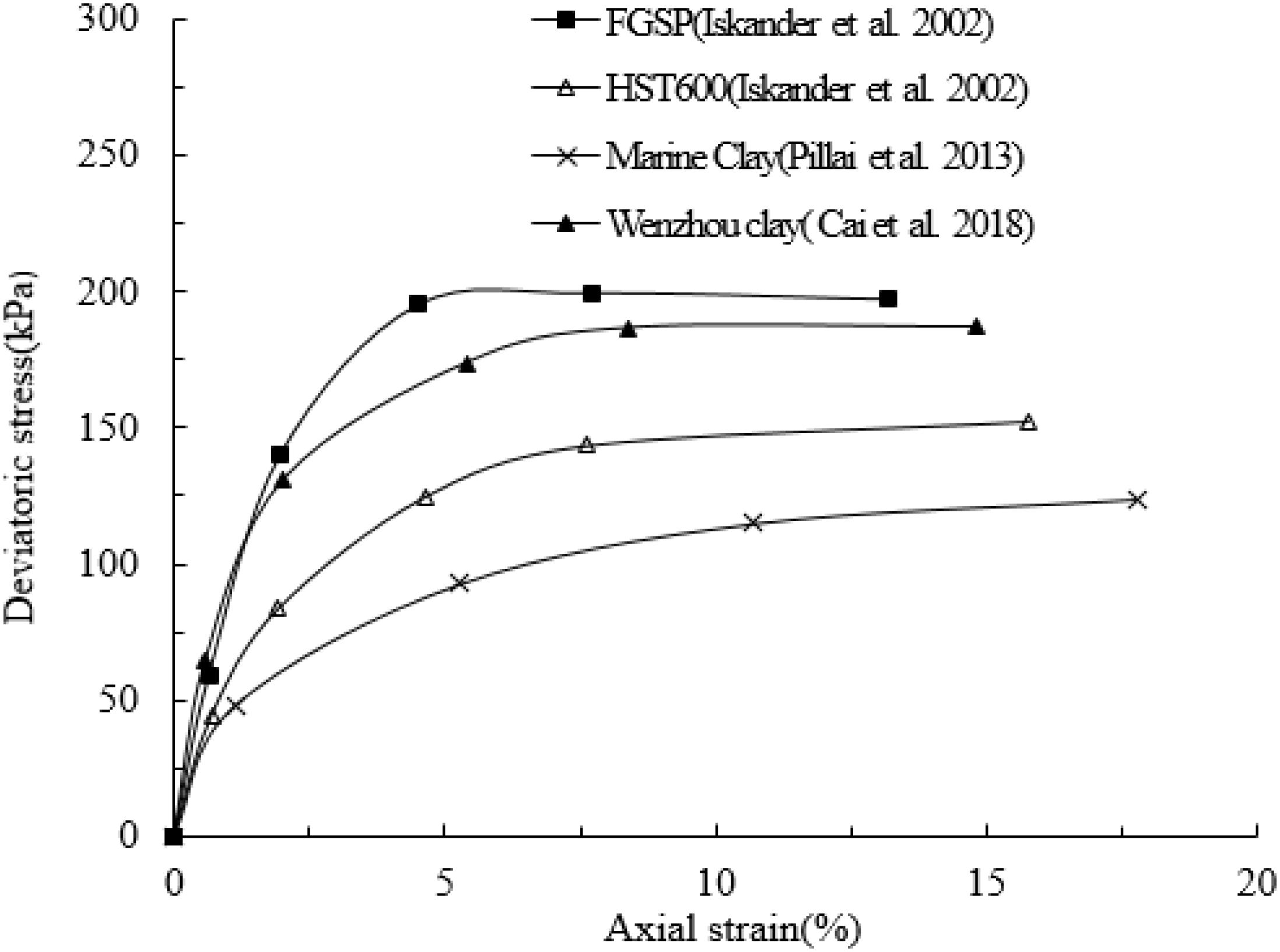
Figure 1. Stress–strain responses of amorphous silica and some natural clays.
Amorphous Silica Gel for Modeling Sand
Silica gel is an inert and porous medium composed of a vast network of interconnected microscopic pores. It has either a round beaded or granular shape and it is available in sizes ranging from 0.5 to 5 mm. The geotechnical properties of silica gel had been investigated, and Liu et al. (2009) found that this material is suitable for modeling natural sand in measuring 3-D internal soil deformation.
Iskander et al. (2010) prepared the transparent “sand” by, respectively, mixing fine and coarse silica gels with a blend of mineral oil and normal-paraffinic solvent with a refractive index of 1.447 and studied the geotechnical properties of transparent specimens. The test results showed that the stress–strain behaviors of both fine and coarse silica are consistent with typical stress–strain behaviors of natural sands, for both dense and loose conditions. The dense specimens made of fine silica exhibited typical strain softening behavior, especially at low confining pressures. For coarse silica specimens, the peak strength occurred at low strain values, which is more consistent with the behavior of the typical natural sand.
From the triaxial tests, the friction angles of fine silica and coarse silica are 30°−36° and 31°−34°, respectively. What’s more, both the fine and coarse silica gels exhibit a higher compressibility than many natural sands, and this should be considered in model tests (Iskander et al., 2002b). In addition, the dynamic properties of silica gel were studied by Zhao and Ge (2007). They pointed out that silica gel displays similar damping behavior as sand under low confining stress, while it does not show the similarity under the condition of high confining stress. Generally, the dynamic properties of coarse silica are found to follow the common trend in sands and gravels.
Fused Silica for Modeling Sand
Fused silica is a calcined product under high temperature and exhibits low thermal conductivity, excellent thermal stability and excellent optical qualities. The physical properties, including the specific gravity of 2.21, Mohs hardness of 7.0, and PH of 6.0 are extremely similar to natural sands and make fused silica an appropriate material to model natural sands. Compared to the two-pore system amorphous silica, fused silica exhibits a better capacity to model natural sand as its one-pore system is more similar to that of natural soils. In order to study the modeling capacity of fused silica, Cao et al. (2011) investigated the geotechnical properties of transparent soil made of fused silica and a calcium bromide solution with a matching refractive index. The results showed that the physical properties of fused silica, in terms of strength, dynamic elastic, and damping ratios, are extremely similar to those of natural sand. And Chang et al. (2017) found that particle sizes of fused silica influence the measurement accuracy of soil deformation. The results suggested that fused silica was the direct factor to the being of laser speckle field and also principal to the quality of the speckle patterns. Besides, the gray-scale images of small particle sizes in transparent soil test distribute more evenly than those of large particle sizes. Fused silica, therefore, is suitable to model natural sand under a low confining pressure condition and can provide a better modeling capacity than amorphous silica.
Glass Sand for Modeling Sand
Compared to silica gel and other materials mentioned above, glass sand has solid particles with no pores inside and a perfect transparency. A new transparent synthetic soil similar to fused silica can be made of glass sand and pore fluid, a 1:4 blend by weight of twelve alkane and white mineral oil with a refractive index of 1.4585 at 24°C. Because of the different heating technology, the purity of glass sand is higher than fused silica. The transparency of this material is demonstrated in Figure 2, where the de-aired suspension was consolidated in a transparent glass beaker. The deformation properties of this new transparent soil were studied by consolidated undrained and drained triaxial compression tests (Kong et al., 2014). The results showed that, with the increasing of the relative density, the stress–strain behavior transforms from strain hardening to strain softening, and deformation modulus of the glass sand and the pore pressure coefficient decrease. Kong et al. (2016) also analyzed the difference by using different materials of pore fluid with glass sand. Under the confining stress of 100 kPa, the stress–strain curves with different pore fluids. The result suggested that the strength with sucrose is the highest while mixed oil is the lowest. Generally, the new transparent soil, composed of glass sand, twelve alkane, and white mineral oil mixture, is suitable for modeling natural sand and can be used to create a visually accurate representation of the internal conditions within soil mass in geotechnical model tests.
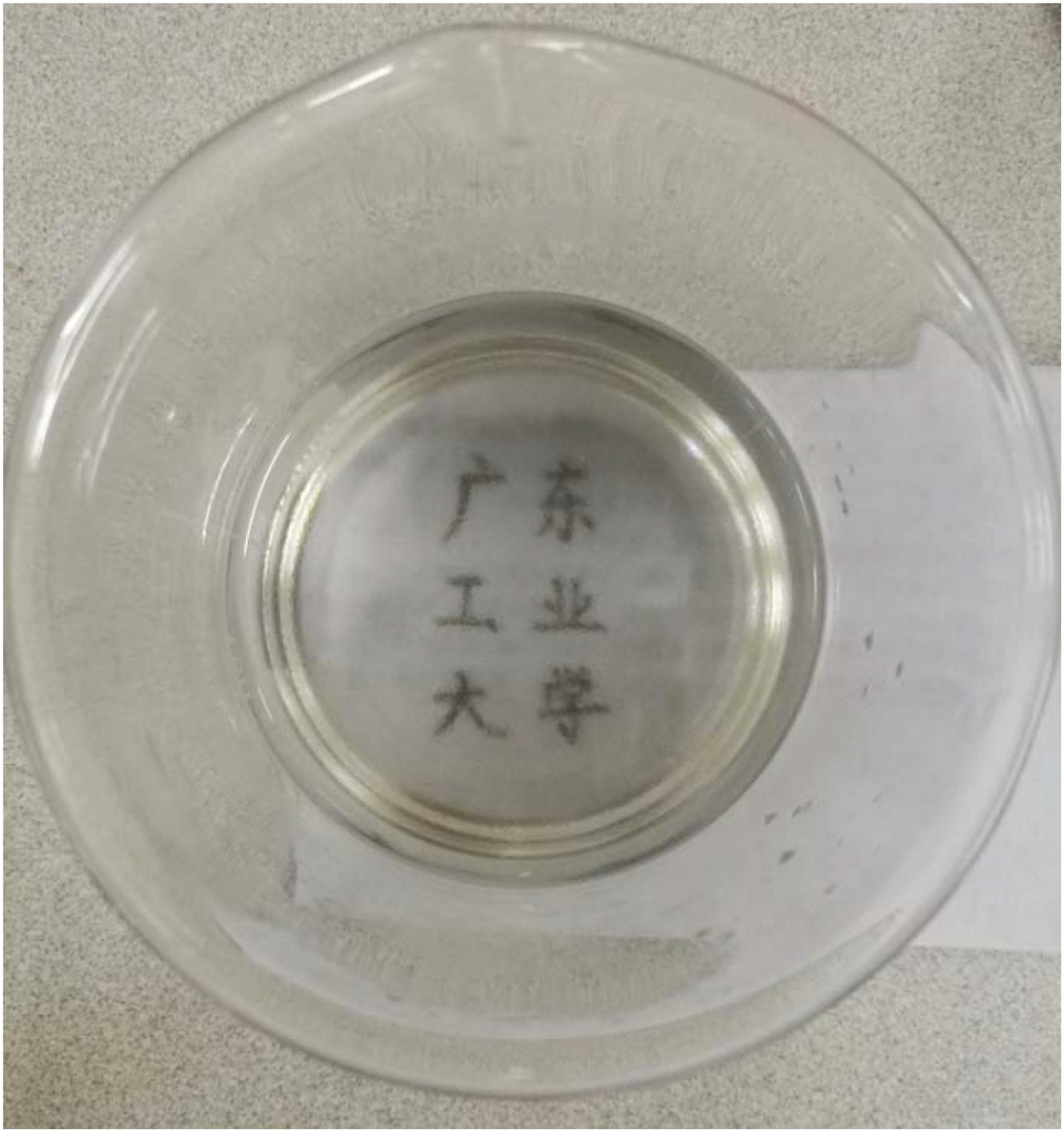
Figure 2. Target viewed through transparent soil model: the words are visible through transparent soil model.
Application of Transparent Soil in Modeling of Soil-Structure Interaction
The continuous deformation measurement of natural soils can be traced back to the 1960s and the 1970s. Bransby and Milligan (1975) and Kirkpatrick and Belshaw (1968) made their first attempt to use X-ray to measure the deformation of interior soil. Orsi et al. (2015) introduced technology of X-ray, CAT scans and MRI scans and other advanced equipments through tracking target particles to obtain the non-intrusive pictures of soil sample. Then the deformation paths of the target particles can be calculated by the deformation analysis techniques. However, the disadvantage is that it is limited by its high cost.
As noted above, various test results indicate that transparent soils exhibit geotechnical properties similar to those of natural soils and can be used to study a wide range of internal soil problems. In the transparent soil techniques, an artificial speckle pattern is generated by the interaction of the laser light and transparent soil. This process relies on an optical system consisting of a laser source, a line-generating lens and a digital camera (Figure 3). Amorphous silica power and silica gel have the same refractive index, which can be used to model stratified conditions in the same model, and the pore fluids, a calcium bromide solution and a 1:1 blend by weight of mineral oil and a normal-paraffinic solvent are not miscible, which permits studying multi-phase flow problems such as the contamination of an aquifer with petroleum products.
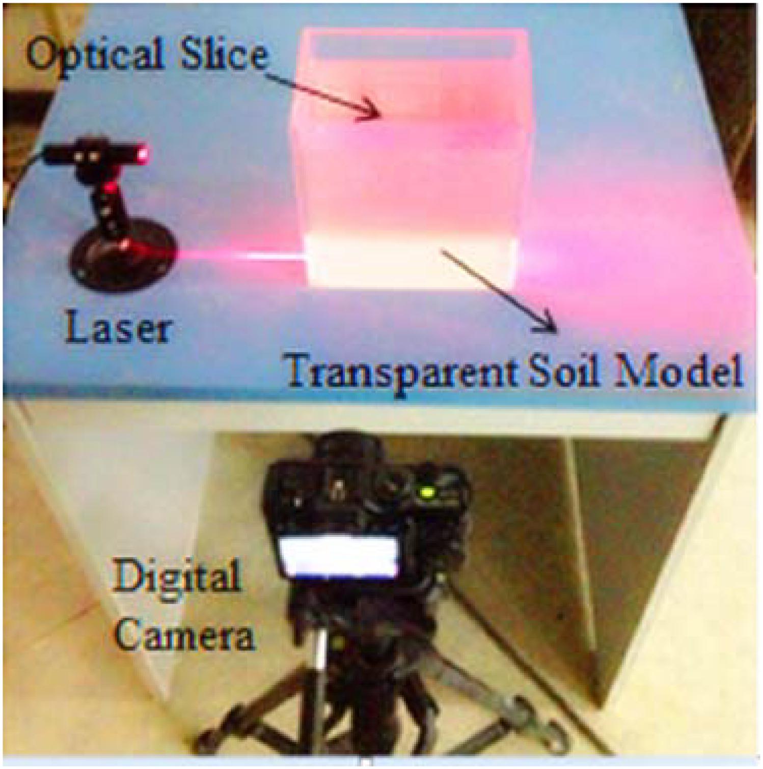
Figure 3. Schematic diagram showing setup for slicing transparent synthetic soils.
For several years, transparent soils have been successfully applied to investigate geotechnical problems. In their fundamental study of tri-axial tests, Wu (2006) proved that transparent soil was similar to natural soil. In addition, Xiang et al. (2018) studied the influence of surrounding rock strength and depth on the deformation and failure mechanism of shallow tunnels through transparent soil technology.
Recently, the digital image technology and optical equipment have been widely used in industry and academia. Tang et al. (2019) developed a method for automatically generating 3D deformed images of the RACSTC surface under low cyclic loading through digital image technology and optical devices. In addition, research on related issues of lining during tunnel excavation. Based on the simulation experiment, Li Y. et al. (2019) used the digital speckle method to measure the surrounding rock fracture zone of the mixed foundation tunnel, and provided suggestions for different support of different regional design for the whole tunnel support. Particle Image Velocimetry (PIV), one of the digital image measurement techniques, can be used to measure the flow field in fluid mechanics (Adrian, 1991). The measurement of the displacement field is based on image pattern matching, which is a classic pattern recognition technique in which two continuous images are correlated to calculate the relative displacement field between them (Yuan et al., 2017). Thus, in the laterally loaded pile modeling test, both horizontal and vertical soil displacement fields can be computed from two pairs of consecutive images captured during the pile movement. According to it, Yuan et al. (2016) investigated the responses of a laterally loaded pile and sand displacement fields in a model test (Figure 4). The results proved the accuracy of the measurement and the feasibility of solving soil-pile interaction problems. By using this model test with natural sand, the internal displacement field could not be observed though the photos of the surface and vertical profile captured during the loading procedure (Yuan et al., 2019). To overcome the limitation of previous study, transparent soil, combined with the PIV technique, was used to study the interior 2D displacement of the sand around the laterally loaded pile. The interior displacement fields at different depth were calculated, as shown in Figure 5. In terms of foundation deformation and bearing capacity, by combining the technologies of PIV and close-range photography, Qi et al. (2015) made a study on the mechanism of soil deformation, analyzing the soil deformation caused by the shallow foundation settlement and proving the modeling test is feasible.
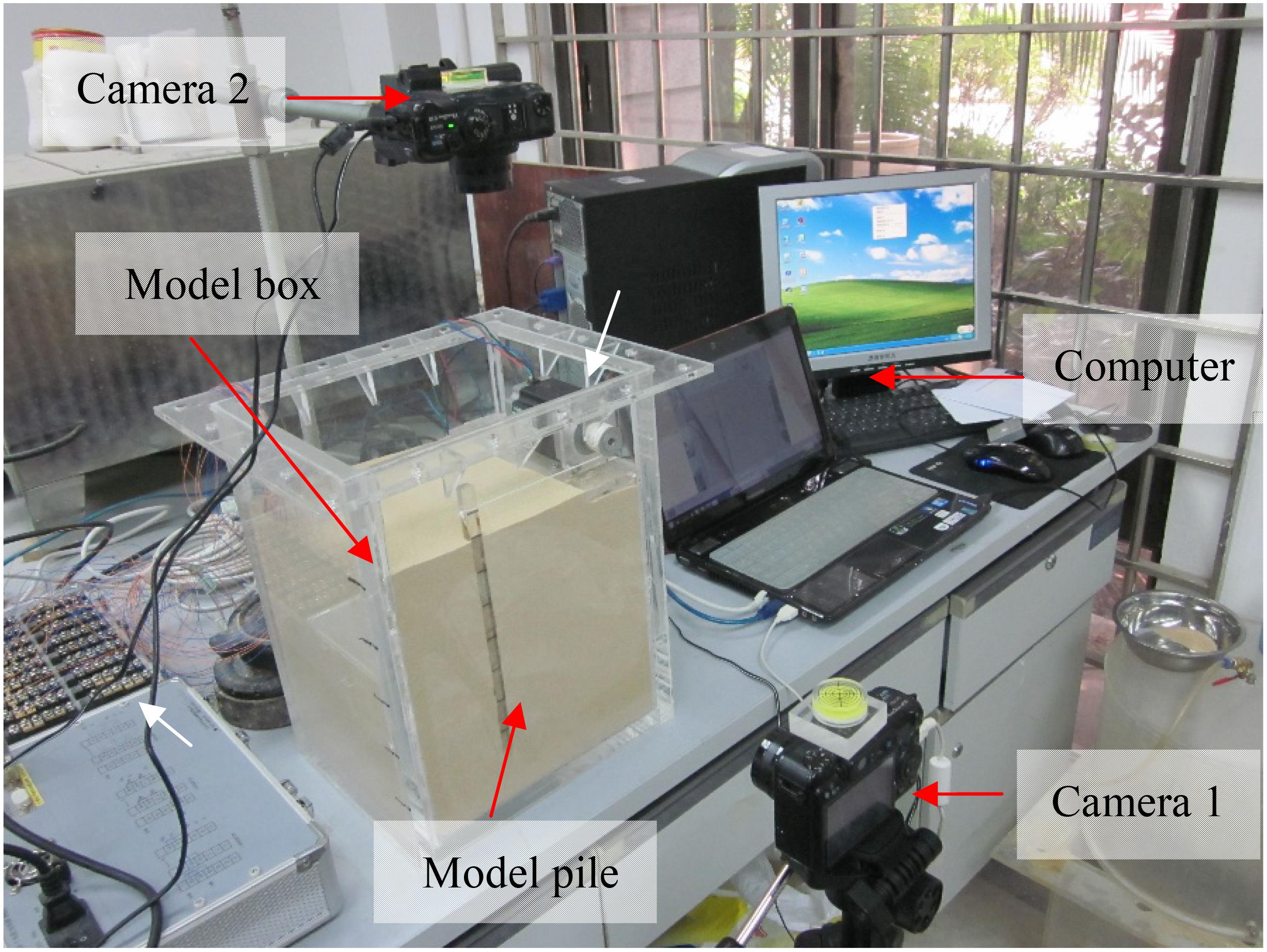
Figure 4. Equipments of the model test.
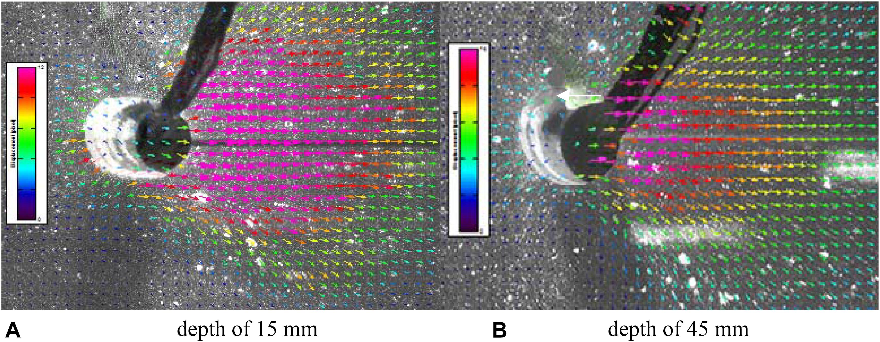
Figure 5. Displacement vector of the soil around the pile at two depths. (A) Depth of 15 mm and (B) depth of 45 mm.
Using the interior 2D displacement fields of the horizontal and vertical profiles (Figure 6), an improved three dimensional (3D) displacement measuring system has been developed to measure the full 3D displacement fields around a laterally loaded pile in transparent soil. The reconstructive procedure of 3D displacement fields includes interpolation of 2D displacements at the profiles, reconstruction of 3D displacement vectors in the intersection points, and interpolation of 3D displacement in the unknown points. In PIV, the position of soil particles is captured continuously by high-definition camera at different time points (Abdi and Mirzaeifar, 2017). Then, combined with PIV analysis program, the displacement of the same particle between two digital images is calculated, and the instantaneous velocity of particles is calculated with time, so the displacement vector map of particles is obtained (Li H. et al., 2019). Thus, the displacement of the pile and soil can be easily observed and calculated from the laboratory test. Figure 7 shows the variation of displacement of piles under loading and Figure 8 shows the full 3D displacement field and contour plots of three slices of XZ plane in the interior transparent soil around the laterally loaded pile. These figures are keys to solving the pile-soil interaction problem.
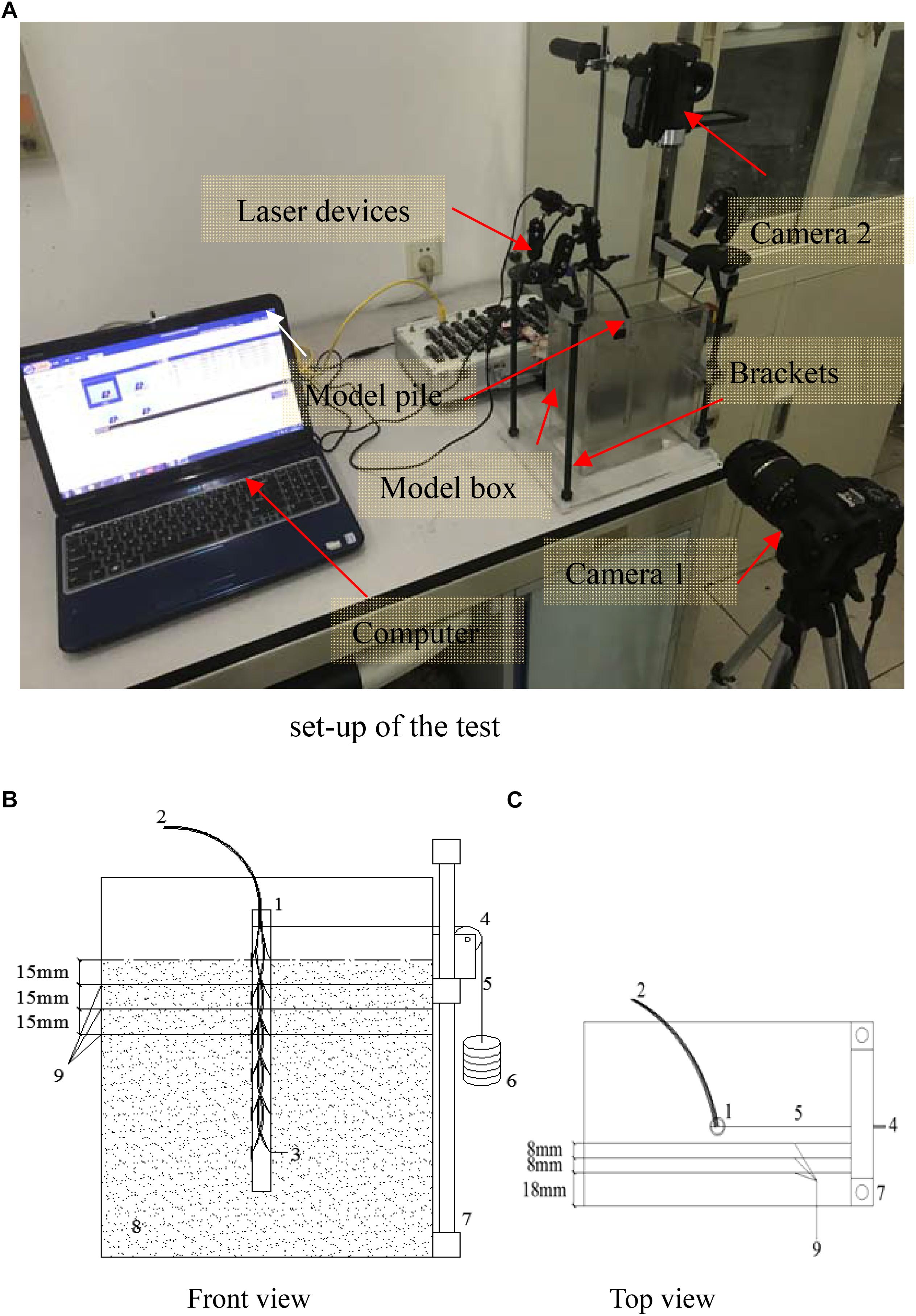
Figure 6. Set-up of the 3D displacement field test: 1. model pile; 2. wire; 3. strain gauge; 4. pulley; 5. line; 6. weight; 7. bracket; 8. transparent soil; 9. laser irradiating surface. (A) Set-up of the test, (B) front view, and (C) top view.
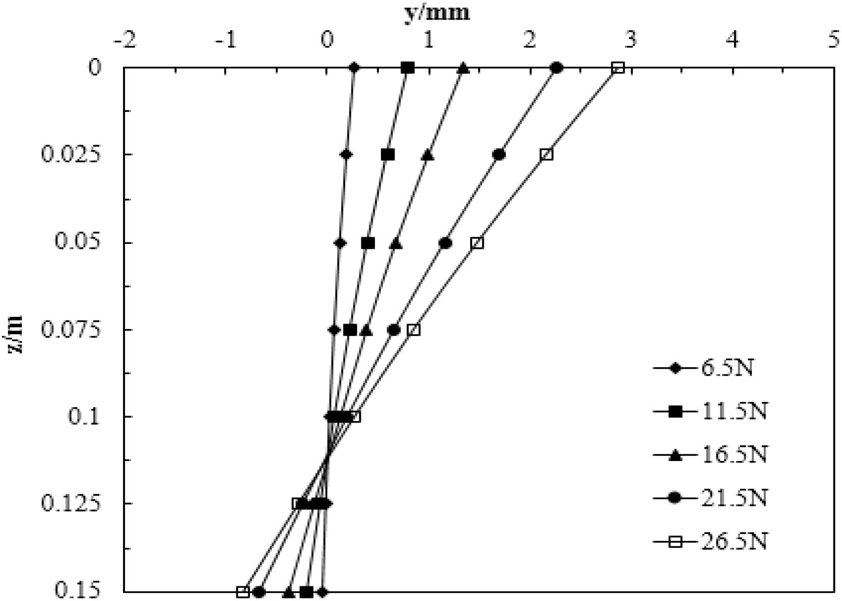
Figure 7. Variation of the pile displacement under lateral load.
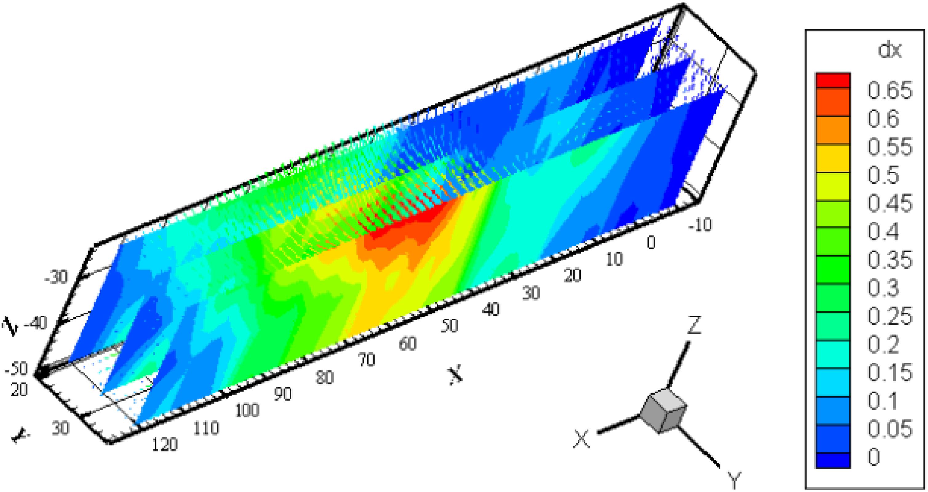
Figure 8. 3D displacement field and contour plots of three slices of XZ plane.
In a pull-out study of anchorages, Xia et al. (2017) set comparative modeling tests by using transparent soil. Using the physical modeling test, different ultimate bearing capacities of anchorages can be analyzed. Using transparent soil, Song et al. (2009) analyzed the change of anchoring force based on centrifuge test. The distribution of interior soil deformation on a transverse section perpendicular to the tunnel was studied using transparent synthetic materials (Sun and Liu, 2014), which showed influence zone in a shallow tunnel was very different from that in a deep tunnel. In the study of flow problems, the grout injection into soil and its permeation process were represented visually by using transparent porous media (Liu et al., 2013). With regard to soil-structure interaction, Ni et al. (2009) studied the soil-pile interaction during penetration and compared the test results with the theoretical predictions of the shallow strain path method. Qi et al. (2015) observed the complete curves of buckling of fully embedded slender piles with different constraint types with transparent soil, finally verifying the movement rule of soil unit was agree with the classical Rankine’s earth pressure theory. All these studies demonstrated that transparent soil techniques can be used to study geotechnical problems.
Based on the feasibility of transparent soil in physical models and the ability to visually represent the internal 3D deformation and flow movements non-intrusively, the understanding of internal soil problems such as deformation mechanism within the soil and failure mechanism has been significantly improved. But transparent soil techniques also have problems, which limit the range of application in the study of geotechnical properties and modeling test. Many large geotechnical projects, which are related to solving geotechnical engineering problems, cannot be analyzed with this technique. Besides, making a good transparency of transparent soil is a hard task. Generally speaking, the models used in modeling tests are small-sized. For a large model, getting appropriate transparency of soil will present problems, such as transparency degradation, transparent samples turning yellow with time, the fault in materials. The test accuracy also deserves more investigations in the future. In order to further promote the transparent soil techniques, there is an urgent need to solve these problems.
Conclusion
Visual enhancement and representation of deformation and flow characteristics within a soil mass in model tests are possible because the response of a transparent continuum model can be measured using non-intrusive optical visualization techniques. Many tests have been performed to study the geotechnical properties of transparent materials. Utilizing the modern optical systems and the techniques of image processing, the internal deformation of soil can be observed accurately. The results validate the feasibility of transparent soil for modeling natural soil if suitable transparent materials are selected, as summarized in Table 1. Transparent soil technique has been successfully applied to study a wide range of soil-structure interaction. A series of modeling tests show the soil-pile interaction mechanism in the internal soil and other relevant geotechnical engineering projects. With a good understanding of the basic theory, the technique can be further improved for more investigations of internal soil problems. Such as the slurry infiltration mechanism and how the slurry infiltration influences the pore water pressure during the construction of shield tunnel. Thus, the promotion of this technology will certainly make a significant difference in internal soil deformation under all kinds of geological conditions.
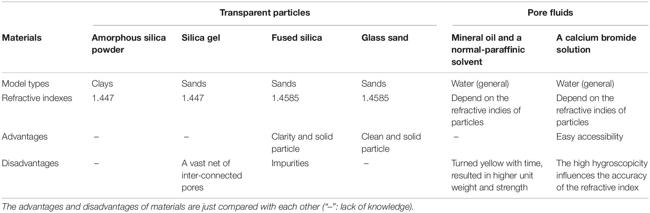
Table 1. Summary of transparent materials.
It is anticipated that transparent soil techniques will play an important role in enhancing the visualization research of soil-structure interaction problems. Therefore, it is suggested to establish a comprehensive test system, including material selection, sample preparation, test index and analog theory.
Data Availability Statement
All datasets generated for this study are included in the article/supplementary material.
Author Contributions
BY wrote the manuscript. LX and XG prepared the test. LZ and YZ prepared the application in civil engineering of the transparent soil. GC and WZ wrote and edited the manuscript.
Funding
The authors would gratefully like to acknowledge the support provided by the CRSRI Open Research Program (Program SN: CKWV2019745/KY), by the National Natural Science Foundation of China (Nos. 51978177 and 51774107), by the Science and Technology Plan Project of Guangdong Provincial Department of Transportation (2017-02-018), and by Natural Science Foundation of Guangdong Province (Nos. 2018A030313839 and 2016A030310345).
Conflict of Interest
The authors declare that the research was conducted in the absence of any commercial or financial relationships that could be construed as a potential conflict of interest.
Acknowledgments
The editorial help from Prof. Galen Leonhardy of the Black Hawk College and Penghui Wen of Guangdong University of Technology is greatly appreciated.
References
Abdi, M. R., and Mirzaeifar, H. (2017). Experimental and PIV evaluation of grain size and distribution on soil–geogrid interactions in pullout test. Soils Foundations 57, 1045–1058. doi: 10.1016/j.sandf.2017.08.030
Adrian, R. (1991). Particle-imaging techniques for experimental fluid mechanics. Annu. Rev. Fluid Mech. 23, 261–304. doi: 10.1146/annurev.fluid.23.1.261
Bransby, P., and Milligan, G. (1975). Soil deformations near cantilever sheet pile walls. Géotechnique 25, 175–195. doi: 10.1680/geot.1975.25.2.175
Cai, Y., Hao, B., Gu, C., Wang, J., and Pan, L. (2018). Effect of anisotropic consolidation stress paths on the undrained shear behavior of reconstituted wenzhou clay. Eng. Geol. 242, 23–33. doi: 10.1016/j.enggeo.2018.05.016
Cao, Z., Liu, J., and Liu, H. (2011). “Transparent fused silica to model natural sand,” in Proceedings of the 2011 Pan Am CGS Geotechnical Conference, (Toronto, TO: Canadian Geotechnical Society, 2011).
Chang, Y., Lei, Z., Zhao, H., and Yu, S. (2017). Influences of grain sizes of fused quartz on displacement measurement accuracy of transparent soil. Rock Soil Mech 38, 493–500.
Chen, J., Quan, W., Yao, G., and Cui, T. (2013). Retrieval of absorption and backscattering coefficients from HJ-1A/CCD imagery in coastal waters. Opt. Express 21, 5803–5821. doi: 10.1364/OE.21.005803
Chen, Y., Wang, X., and Chen, L. (2011). Overview on transparent soil and its application in model tests in geotechnical engineering. Adv. Sci. Tech. Water Res. 31, 69–73.
Cui, C., Meng, K., Liang, Z., Xu, C., Yang, G., and Zhang, S. (2018a). Effect of radial homogeneity on low-strain integrity detection of a pipe pile in a viscoelastic soil layer[J]. Int. J. Distribut. Sens. Netw. 14, 1–8.
Cui, C., Meng, K., Wu, Y., Chapman, D., and Liang, Z. M. (2018b). Dynamic response of pipe pile embedded in layered visco-elastic media with radial inhomogeneity under vertical excitation[J]. Geomech. Eng. 16, 609–618.
Iskander, M., Liu, J., and Sadek, S. (2002a). Transparent amorphous silica to model clay. J. Geotech. Geoenviron. Eng. 128, 262–273. doi: 10.1061/(asce)1090-0241(2002)128:3(262)
Iskander, M., Sadek, S., and Liu, J. (2002b). Optical measurement of deformation using transparent silica gel to model sand. Int. J. Phys. Model. Geotech. 2, 13–26. doi: 10.1680/ijpmg.2002.2.4.13
Iskander, M., Sadek, S., and Ge, L. (2010). Geotechnical Properties of Silica Gels. Berlin: Springer, 85–115.
Iskander, M. G., and Liu, J. (2003). Consolidation and permeability of transparent amorphous silica. Geotech Testing J. 26, 390–401.
Kirkpatrick, W. M., and Belshaw, D. J. (1968). On the interpretation of the triaxial test. Géotechnique 18, 336–350. doi: 10.1680/geot.1968.18.3.336
Kong, G., Liu, L., Liu, H., and Cao, Z. (2014). Comparative analysis of the strength characteristics of transparent glass sand and standard sand. J. Build. Mat. 17, 250–255.
Kong, G., Sun, X., Li, H., and Cao, Z. (2016). Effect of pore fluid on strength properties of transparent soil. Chin. J. Geotech. Eng. 38, 377–384.
Li, H., Tang, C., Cheng, Q., Li, S., Gong, X., and Shi, B. (2019). Tensile strength of clayey soil and the strain analysis based on image processing techniques. Eng. Geo. 253, 137–148. doi: 10.1016/j.enggeo.2019.03.017
Li, Y., Tang, X., Yang, S., and Chen, J. (2019). Evolution of the broken rock zone in the mixed ground tunnel based on the DSCM. Tunnel. Undergr. Space Tech. 84, 248–258. doi: 10.1016/j.tust.2018.11.017
Liu, J., Gao, Y., and Sui, W. (2013). “Visualization of grout permeation inside transparent soil,” in Proceedings of the International Conference on Geotechnical and Earthquake Engineering, Vol. 129, (Virgini, VA: ASCE), 188–194.
Liu, J., Zhang, C., Yu, X., Fu, H., and Zhang, J. (2009). “Visualizing 3-D internal soil deformation using laser speckle and transparent soil techniques,” in Proceedings of the Geohunan International Conference: Challenges and Recent Advances in Pavement Technologies and Transportation Geotechnics, (Changsha Hunan: ASCE), 123–128.
Lu, M., Li, D., Jing, H., and Deng, Y. (2019). Analytical solution for consolidation of band-shaped drain based on an equivalent annular drain. Int. J. Geomech. 19:04019043. doi: 10.1061/(asce)gm.1943-5622.0001423
Mandava, S. S., Watson, A. T., and Edwards, C. M. (2010). NMR imaging of saturation during immiscible displacements. Aiche J. 36, 1680–1686. doi: 10.1016/j.mri.2014.01.021
Ni, Q., Hird, C., and Guymer, I. (2009). Physical modelling of pile penetration in clay using transparent soil and particle image velocimetry. Géotechnique 60, 121–132. doi: 10.1680/geot.8.p.052
Orsi, T. H., Aubrey, L., John, N., William, R., and Edwards, C. (2015). “Use of X-Ray computed tomography in the study of marine sediments,” in Proceedings of the Civil Engineering in The Oceans V International Conference, (College Station, TX: American Society of Civil Engineers).
Pillai, R. J., Bushra, I., and Robinson, R. G. (2013). Undrained triaxial behavior of cement treated marine clay. Geotech. Geol. Eng. 31, 801–808. doi: 10.1007/s10706-012-9605-3
Qi, C., Chen, Y., Wang, X., and Zuo, D. (2015). Physical modeling study on buckling of slender pile using transparent soil. Chin. J. Rock Mech. Eng. 34, 1–10.
Qi, C., Zheng, J., Zuo, D., and Chen, G. (2017). Measurement on soil deformation caused by expanded-base pile in transparent soil using particle image velocimetry (PIV). J. Mountain Sci. 14, 1655–1665. doi: 10.1007/s11629-016-4025-0
Song, Z., Hu, Y., Oloughlin, C., and Randolph, M. (2009). Loss in anchor embedment during plate anchor keying in clay. J. Geotech. Geoenviron. Eng. 135, 1475–1485. doi: 10.1061/(asce)gt.1943-5606.0000098
Suits, L. D., Sheahan, T. C., Iskander, M., and Liu, J. Y. (2010). Spatial deformation measurement using transparent soil. Geotech. Test. J. 33, 314–321.
Sun, J., and Liu, J. (2014). Visualization of tunnelling-induced ground movement in transparent sand. Tunnel. Undergr. Space Technol. 40, 236–240. doi: 10.1016/j.tust.2013.10.009
Tang, Y., Li, L., Wang, C., Chen, M., Feng, W., Zou, X., et al. (2019). Real-time detection of surface deformation and strain in recycled aggregate concrete-filled steel tubular columns via four-ocular vision. Robot Comput.Integr. Manuf. 59, 36–46. doi: 10.1016/j.rcim.2019.03.001
Wang, Y., Guo, P., Dai, F., Li, X., Zhao, Y., and Liu, Y. (2018). Behavior and modeling of fiber-reinforced clay under triaxial compression by combining the superposition method with the energy-based homogenization technique. Int. J. Geomech. 18:04018172. doi: 10.1061/(asce)gm.1943-5622.0001313
Wang, Y., Guo, P., Ren, W., Yuan, B., Yuan, H., Zhao, Y., et al. (2017). Laboratory investigation on strength characteristics of expansive soil treated with jute fiber reinforcement. Int. J. Geomech. 17:04017101. doi: 10.1061/(asce)gm.1943-5622.0000998
Wang, Y., Shan, S., Zhang, C., and Guo, P. (2019). Seismic response of tunnel lining structure in a thick expansive soil stratum. Tunnel. Undergr. Space Technol. 88, 250–259. doi: 10.1016/j.tust.2019.03.016
Wong, R. C. K. (1999). Mobilized strength components of Athabasca oil sand in triaxial compression. Can. Geotech. 36, 718–735. doi: 10.1139/cgj-36-4-718
Wu, M. (2006). Study on Transparent Synthetic Sand and Its Triaxial Test. Master Dissertation, Dalian University of Technology, Dalian.
Xia, Y., Chen, C., and Ni, Q. (2017). Comparative modelling of pull-out process of four different anchorages by using transparent soil. Chin. J. Geotech. Eng. 39, 399–407.
Xiang, Y., Liu, H., Zhang, W., Chu, J., Zhou, D., and Xiao, Y. (2018). Application of transparent soil model test and DEM simulation in study of tunnel failure mechanism. Tunnel. Undergr. Space Techonol. 74, 178–184. doi: 10.1016/j.tust.2018.01.020
Yuan, B., Chen, R., Li, J., Wang, Y., and Chen, W. (2016). A hydraulic gradient similitude testing system for studying the responses of a laterally loaded pile and soil deformation. Environ. Earth Sci. 75, 1–7.
Yuan, B., Sun, M., Wang, Y., Zhai, L., Luo, Q., and Zhang, X. (2019). Full 3D displacement measuring system for 3D displacement field of soil around a laterally loaded pile in transparent soil. ASCE. Int. J. Geomech. 19:04019028. doi: 10.1061/(asce)gm.1943-5622.0001409
Yuan, B., Xu, K., Wang, Y., Chen, R., and Luo, Q. (2017). Investigation of deflection of a laterally loaded pile and soil deformation using the PIV technique. Int. J. Geomech. 17:04016138. doi: 10.1061/(asce)gm.1943-5622.0000842
Zhao, H., and Ge, L. (2007). “Dynamic properties of transparent soil,” in Dynamic Response and Soil Properties, ASCE Geotechnical Special Publication No. 160, eds M. M. Dewoolkar and J. P. Koester (Virginia, VA: ASCE).
Zhao, Y., Wang, Y., Wang, W., Tang, L., Liu, Q., and Cheng, G. (2019). Modeling of rheological fracture behavior of rock cracks subjected to hydraulic pressure and far field stresses. Theor. Appl. Fracture Mech. 101, 59–66. doi: 10.1016/j.tafmec.2019.01.026
Zhao, Y., Wang, Y., Wang, W., Wan, W., and Tang, J. (2017). Modeling of non-linear rheological behavior of hard rock using triaxial rheological experiment. Int. J. Rock Mech. Min. Sci. 93, 66–75. doi: 10.1016/j.ijrmms.2017.01.004
Keywords: transparent synthetic soil, amorphous silica powder, amorphous silica gel, fused silica, transparent glass sand, optical test
Citation: Yuan B, Xiong L, Zhai L, Zhou Y, Chen G, Gong X and Zhang W (2019) Transparent Synthetic Soil and Its Application in Modeling of Soil-Structure Interaction Using Optical System. Front. Earth Sci. 7:276. doi: 10.3389/feart.2019.00276
Received: 01 August 2019; Accepted: 11 October 2019;
Published: 24 October 2019.
Edited by:
Yanlin Zhao, Hunan University of Science and Technology, ChinaReviewed by:
Chunyi Cui, Dalian Maritime University, ChinaYong Hong Wang, Qingdao University of Technology, China
Feifan Ren, Tongji University, China
Copyright © 2019 Yuan, Xiong, Zhai, Zhou, Chen, Gong and Zhang. This is an open-access article distributed under the terms of the Creative Commons Attribution License (CC BY). The use, distribution or reproduction in other forums is permitted, provided the original author(s) and the copyright owner(s) are credited and that the original publication in this journal is cited, in accordance with accepted academic practice. No use, distribution or reproduction is permitted which does not comply with these terms.
*Correspondence: Xing Gong, OTgyNTU1MjEyQHFxLmNvbQ==