 Matthew A. Thomas1*†
 Alejandro Mota2
 Benjamin M. Jones3
 R. Charles Choens2Jennifer M. Frederick2Diana L. Bull2
- 1U.S. Geological Survey, Geologic Hazards Science Center, Golden, CO, United States
- 2Sandia National Laboratories, Albuquerque, NM, United States
- 3Institute of Northern Engineering, College of Engineering and Mines, University of Alaska Fairbanks, Fairbanks, AK, United States
Scientific knowledge and engineering tools for predicting coastal erosion are largely confined to temperate climate zones that are dominated by non-cohesive sediments. The pattern of erosion exhibited by the ice-bonded permafrost bluffs in Arctic Alaska, however, is not well-explained by these tools. Investigation of the oceanographic, thermal, and mechanical processes that are relevant to permafrost bluff failure along Arctic coastlines is needed. We conducted physics-based numerical simulations of mechanical response that focus on the impact of geometric and material variability on permafrost bluff stress states for a coastal setting in Arctic Alaska that is prone to toppling mode block failure. Our three-dimensional geomechanical boundary-value problems output static realizations of compressive and tensile stresses. We use these results to quantify variability in the loci of potential instability. We observe that niche dimension affects the location and magnitude of the simulated maximum tensile stress more strongly than the bluff height, ice wedge polygon size, ice wedge geometry, bulk density, Young's Modulus, and Poisson's Ratio. Our simulations indicate that variations in niche dimension can produce radically different potential failure areas and that even relatively shallow vertical cracks can concentrate displacement within ice-bonded permafrost bluffs. These findings suggest that stability assessment approaches, for which the geometry of the failure plane is delineated a priori, may not be ideal for coastlines similar to our study area and could hamper predictions of erosion rates and nearshore sediment/biogeochemical loading.
Introduction
Permafrost coastlines account for one-third of the global coastline (Lantuit et al., 2012). Declining sea ice in the Arctic Ocean has increased the length of the open-water season, exposing permafrost coastlines to more frequent and intense forms of wave energy and storm surge (Maslanik et al., 2007; Serreze et al., 2007; Overeem et al., 2011; Simmonds and Rudeva, 2012; Stammerjohn et al., 2012; Vermaire et al., 2013; Barnhart et al., 2014a). Annual rates of erosion along ice-rich portions of the Arctic Alaska coast have doubled since the middle of the twentieth century (Jorgenson and Brown, 2005; Mars and Houseknecht, 2007; Jones et al., 2009, 2018; Ping et al., 2011; Gibbs and Richmond, 2015; Gibbs et al., 2017) and are accelerating to values that are among the highest in the world (up to 20–30 m yr−1; Reimnitz et al., 1988; Wobus et al., 2011; Barnhart et al., 2014b). Elevated erosion rates in the Arctic are projected to have significant environmental impacts on global carbon fluxes and marine food webs (Vonk et al., 2012; Fritz et al., 2017).
Much of Arctic Alaska is inaccessible by all-season roads; therefore, people and infrastructure are concentrated near the coastline. Native coastal villages in Alaska are now more frequently affected by erosion, with more than 30 facing relocation (U.S. Government Accountability Office, 2004, 2009). Active U.S. Department of Defense long-range Arctic coastal radars, which are dedicated to maintaining national sovereignty in the air, are experiencing higher-than-expected rates of bluff retreat (Hughes, 2016). Coastal erosion in Arctic Alaska is projected to increase the cost of maintaining infrastructure (e.g., roads and pipelines) by billions of dollars in the coming decades (Larsen et al., 2008). The financial impact of enhanced coastal erosion will likely be further exacerbated by emerging geopolitical pressures, including the discovery of natural resources (e.g., hydrocarbons and minerals) and the opening of new shipping routes and the construction of support facilities in the Arctic (Clement et al., 2013).
Thermo-denudation and thermo-abrasion are two thermal-mechanical processes that dominate the Arctic coastal erosion problem (Aré, 1988a,b; Günther et al., 2013). Thermo-denudation refers to the subaerial degradation of permafrost, which triggers ground failure that proceeds under the influence of gravity, typically in the form of subsidence or slumping. Thermo-abrasion refers to the combined effect of thermal and mechanical erosion of ice-rich permafrost bluffs due to wave action. Here, the parent material at the base of the bluff is warmed by the ocean and removed by the mechanical action of waves. A recess at the base of the bluff, commonly referred to as a “thermo-erosional niche,” progresses landward until the overhanging material fails via translational or toppling mode block failure (Hoque and Pollard, 2009).
Pioneering studies that focused on simulating niche formation in frozen coastal bluffs developed an analytical solution for one-dimensional heat transfer that predicts niche depth as a function of nearshore oceanographic conditions including water temperature, water level, and storm duration (Kobayashi, 1985; Kobayashi and Aktan, 1986). Due to the high ice content of many permafrost bluffs, more recent studies that have focused on simulating niche formation (e.g., Wobus et al., 2011) have adopted empirical equations that were originally designed to predict the melting rate of free-drifting icebergs (e.g., Russell-Head, 1980; White et al., 1980). These computationally efficient, rule-based niche advancement models have been paired with geometric criteria, such a critical niche depth (Ravens et al., 2012), or limit-equilibrium expressions to develop stability nomograms (Hoque and Pollard, 2009, 2016) and quantify bluff retreat rates (e.g., Barnhart et al., 2014b). An important theme that has emerged from these scientific contributions is the episodic nature of block failure in coastal permafrost systems, a key factor in estimating coastal erosion rates meant to guide land-use decisions (Thomas and Loague, 2016).
A less-studied component of permafrost bluff erosion is the mechanical behavior of the bluff leading up to failure. Stress is an important mechanical factor because it is the physical state variable that responds to the oceanographic forcings that affect the spatiotemporal characteristics of niche development and subsequent bluff failure (Frederick et al., 2016). Herein, we employ physics-based geomechanical simulation, in a concept-development mode (Loague et al., 2010), to quantify the impact of bluff geometry and material variability on stress states for coastal permafrost coastlines that are susceptible to toppling mode block failure. Our numerical simulation approach is advantageous in that it is based on measurable physical properties (as opposed to indirect analytical or empirical proxies). Furthermore, the potential failure does not need to be defined a priori, but rather, can be interpreted from the multidimensional patterns of stress produced by the model. The value of the work we present here lies in its ability to (1) improve process-based understanding of coastal permafrost bluff failure characteristics and (2) provide a foundation for more complex simulation scenarios geared toward resolving long-term erosion rates from an event-based perspective.
Drew Point, Alaska
The geomechanical simulation scenarios that we formulated are informed by observations from Drew Point, Alaska. Located ~100 km east of Utqiagvik (formerly known as Barrow; Figure 1A), the 9-km stretch of coastline at Drew Point consists of low-lying (~5 m average height; Jones et al., 2018) bluffs that are set amid a broad coastal plain (Figure 1B). The bluffs host a network of ice wedges (1–3 m wide, 3–5 m deep; Jones et al., 2018) and ice wedge polygons (15 m average width; Jones et al., 2018) with fine-grained, ice-bonded marine sediments (~40–90% ice by volume; Ping et al., 2011; Wobus et al., 2011; Kanevskiy et al., 2013; Barnhart et al., 2014b; Figure 1C) that were deposited in the late Quaternary (Jones et al., 2018). These bluff height and ice-content characteristics are typical for ~25% of the Beaufort Sea coast (Barnhart et al., 2014b). The bluff stratigraphy at Drew Point includes vegetative matting, an active (seasonably unfrozen) surficial layer, and a complex sequence of terrestrial- and marine-derived sediments. Nearshore water depths at Drew Point are shallow (<2 m within 0.5 km of the shoreline; Jones et al., 2018) and exhibit microtidal (~15 cm, daily to monthly; Barnhart et al., 2014b) fluctuations. During the sea ice-free summer/fall season, storms raise nearshore water levels and undercut the bluffs via thermo-abrasion (Figures 2A,B) until a toppling mode block failure occurs (Figure 2C). Although small-scale shear modes may exist, toppling appears to be the dominant failure mechanism at Drew Point. Typically, the failed blocks disintegrate in the nearshore environment (Figure 2D) over the course of days to weeks, providing only short-term armoring against further retreat (Barnhart et al., 2014b; Jones et al., 2018).
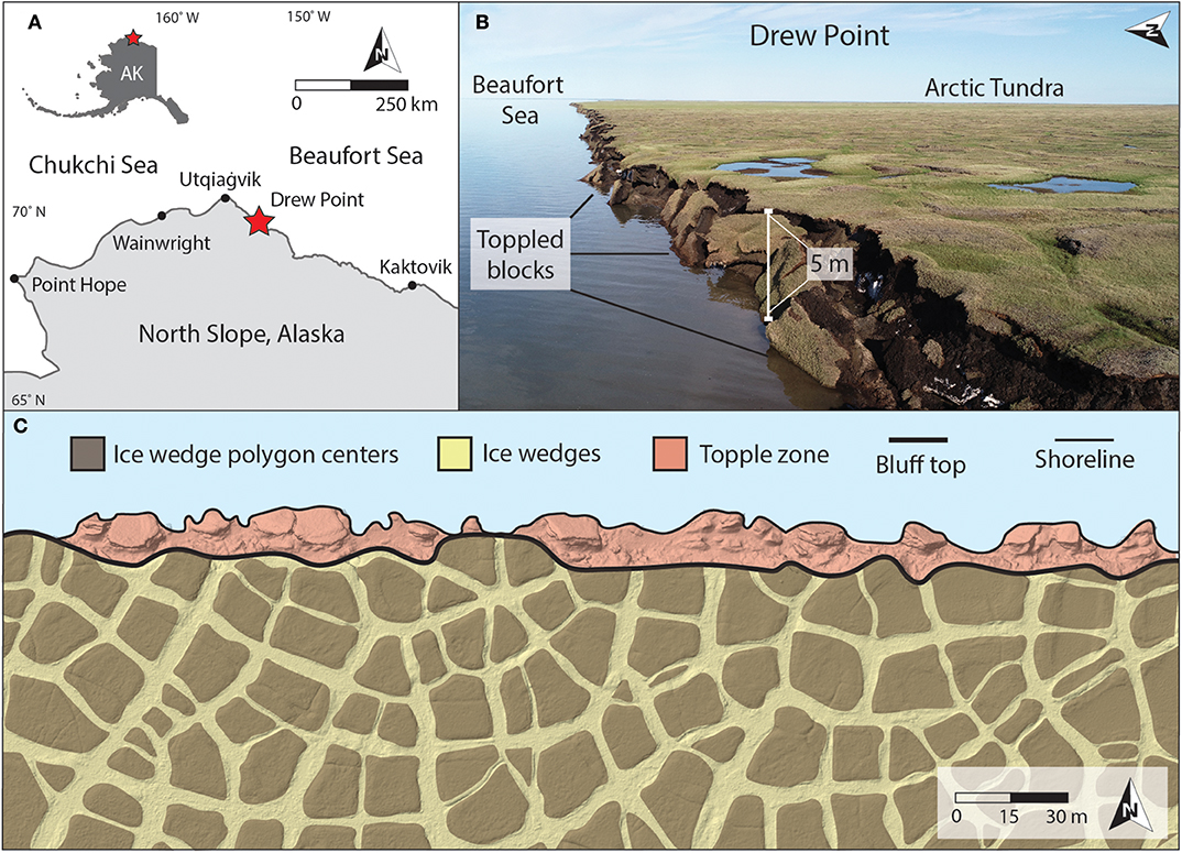
Figure 1. (A) Location of the Drew Point study area (red star) along the north coast of Alaska, USA. (B) Oblique aerial view acquired by unmanned aerial vehicle (UAV) showing toppling mode block failure that is typical along the coastline at Drew Point. (C) UAV orthophoto mosaic showing the permafrost terrain configuration at Drew Point consisting of ice wedges, ice wedge polygon networks, and the topple zone. Roughly 75% of the block failures in this example occurred along an ice wedge, whereas 25% occurred in an ice wedge polygon center.
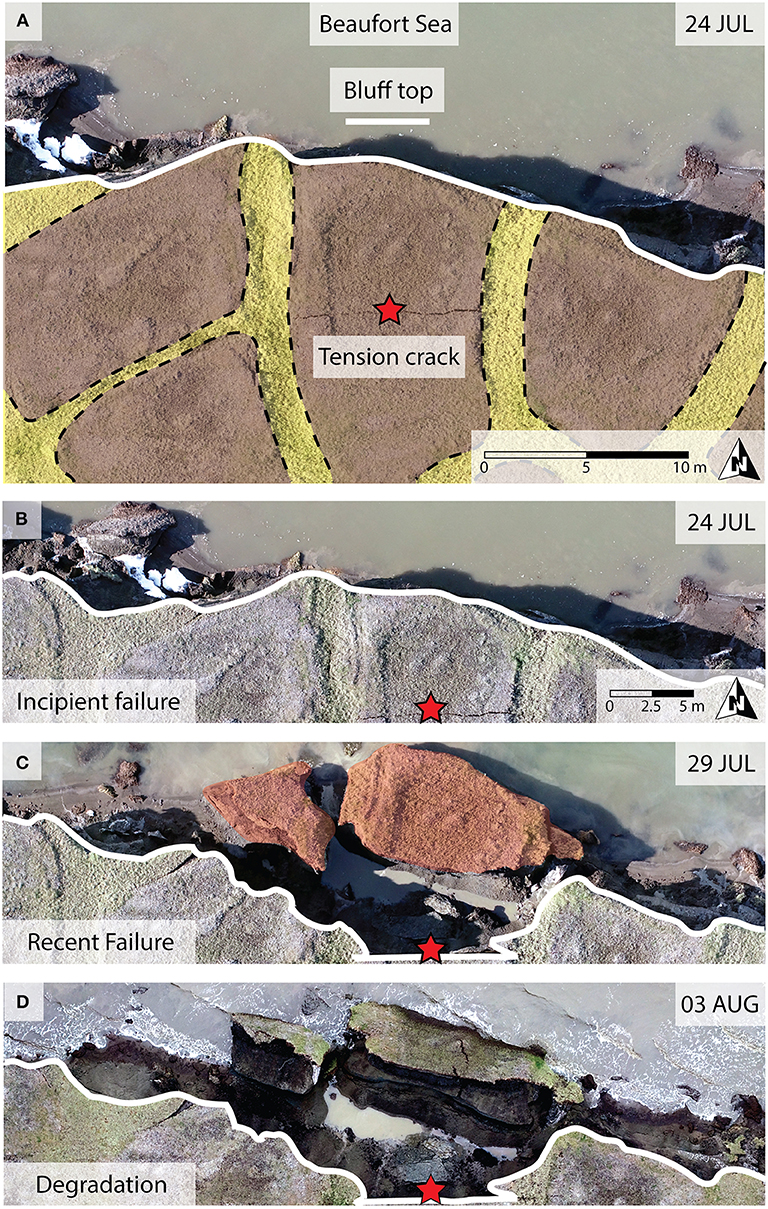
Figure 2. (A) Unmanned aerial vehicle (UAV)-based orthophoto mosaic of a tension crack (red star) visible on 24 July 2018. The local bluff height, niche height, and niche depth are approximately 4.9, 1.9, and 4.5 m, respectively. Yellow and brown shaded areas highlight ice wedges and polygon centers, respectively. Sequence of repeat UAV-based orthophoto mosaics showing (B) incipient failure (24 July), (C) recent failure (29 July), and (D) degradation of the permafrost block in the nearshore environment (03 August).
Methods
We applied continuum mechanics theory with static simulations of three-dimensional (3D) heterogeneous elastic finite deformation to assess the impacts of bluff geometry and material variability on stress states leading up to permafrost bluff failure. We present the modeled state of stress here with the linear elastic equation, as the extent of deformation prior to the toppling block failure of the rigid, ice-rich permafrost bluff materials in our study area is relatively small over short (i.e., daily to weekly) timescales and well-approximates elastic finite deformation theory. Linear elastic theory has been used to examine stresses for vertical bluff geometries in a number of lower latitude, non-permafrost settings (e.g., Young and Ashford, 2008; Collins and Sitar, 2011; Lu et al., 2012). Static 3D linear elastic stress with a gravitational body force can be expressed (see Rao, 2007) as:
where σ is the stress [M/LT2], ρb is the (permafrost or ice wedge) bulk density [M/L3], g is the acceleration due to gravity [L/T2], and x-y-z are the map-view and vertical coordinates [L]. The nine components of stress within the equilibrium equations are defined by:
where ε is the strain [dimensionless], λ and μ are Lamé parameters [M/LT2], and Δ = εxx + εyy + εzz. The nine components of strain are given as:
where u, v, and w are displacement components [L] parallel to the x, y, z axes. The Lamé parameters are:
and
where E is the Young's modulus [M/LT2] and υ is Poisson's Ratio [dimensionless] for permafrost or ice wedge.
The numerical code that we used is Albany, an open-source implicit unstructured finite-element application (Salinger et al., 2016; Sandia National Laboratories, 2017). The simulation domain is made up of square permafrost blocks intersected by a regular network of ice wedges (simplified as rectangular prisms) and is discretized with ~2 ×10⁴ nodes at 1-m average grid spacing (Figure 3). We did not include the active layer in our simulation framework for this study because its vertical extent is minimal (~25 cm depth compared to the 5 m average bluff height) and its mechanical properties are poorly constrained for our study region. The lateral and rear surfaces, which include half ice wedge thicknesses, are symmetry-type displacement boundary conditions which mirror stress across the boundary. The basal surface is a fixed boundary with zero displacement, while the topographic surface and bluff face are free surfaces subject to displacement. The central portion of the bluff face is laterally separated by at least one permafrost block to reduce the impact of the displacement-type boundary conditions on the area of interest (i.e., cross section X-X″ in Figure 3). The geomechanical boundary-value problem produces steady-state snapshots of stress and displacement (Figure 4). These simulations facilitated examination of stress patterns within the bluff and identification of the location and magnitude of the maximum tensile stress (σTmax) that forms along the topographic surface. The σTmax, created by a bending moment along the bluff face (Figure 4A), is an important metric because it reflects a likely initiation location for toppling mode block failure.
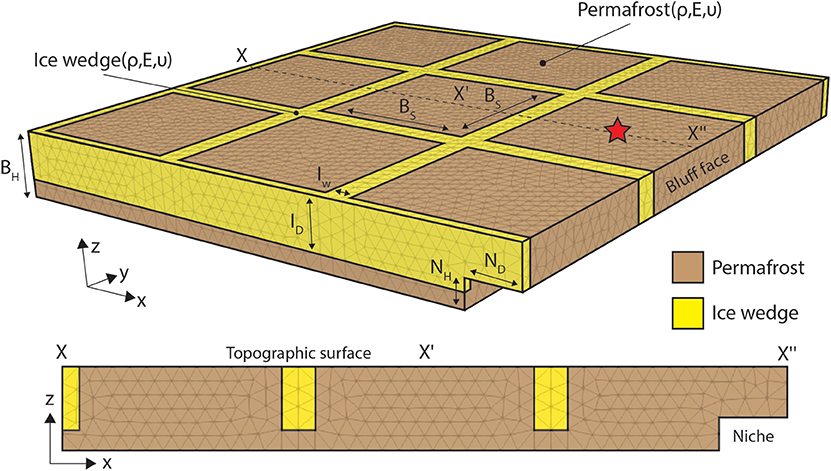
Figure 3. Schematic of the base case three-dimensional geomechanical boundary-value problem (BVP). Geometric properties include the niche height (NH), niche depth (ND), ice wedge depth (ID), ice wedge width (IW), permafrost block size (BS), and bluff height (BH). Material properties include the bulk density (ρ), Young's Modulus (E), and Poisson's Ratio (υ) for ice wedges (yellow) and permafrost (brown). The red star corresponds to the approximate location of the tension crack that is visible in Figure 2.
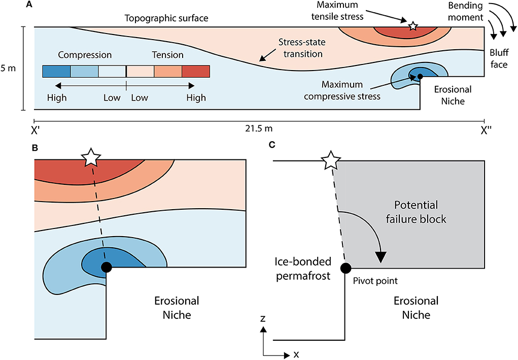
Figure 4. (A) Conceptual cross section (X′-X″ in Figure 3) of patterns of stress based on elastic geomechanical simulation. (B) Enlargement of stress field in the vicinity of the bluff face and erosional niche. Dashed black line connects the points of maximum tensile and compressive stress. (C) Diagram of potential toppling mode block failure (gray area) about a pivot point (black circle).
The modeling strategy that we adopted for this study was not an event-based reconstruction of stress encompassing bluff failure, but rather an evaluation of how the σTmax is influenced by plausible variations in bluff geometry and the material properties. These variations are not meant to serve as validation cases for Drew Point or encompass all possibilities, but rather, serve as a set of plausible, internally consistent numerical experiments to quantify the relative impact of geometric and material variability on the bluff's stress state. The geometric characteristics that we considered (Figure 3) are niche height (NH), niche depth (ND), bluff height (BH), permafrost block size (BS), ice wedge thickness (IW), and ice wedge depth (ID). These characteristics were informed by field observations (e.g., hand survey methods such as a tape measure) and visual inspection of UAV-based aerial photography, as opposed to a formal statistical analysis. A series of UAV-derived orthophoto mosaics were created with Pix4D Mapper version 4.3.31 using ~750 images in each survey acquired on 24 July 2018, 29 July 2018, and 03 August 2018, from a DJI Phantom 4 Pro V2 UAV for a 0.3 km2 area located at Drew Point (Figure 2). We used the photos to examine ice wedge geometries, ice wedge polygon dimensions, niche dimensions, block failure locations relative to ice wedges, and block failure sizes. The ice wedge and permafrost mechanical properties that we considered (Figure 3) are bulk density (ρb), Young's Modulus (E), and Poisson's Ratio (υ). The base case geometric and material parameter values (Table 1) represent the median of the bounding values that we observe in the field and laboratory, respectively. The base case geometric parameter values also approximate geometric conditions that we have observed just prior to bluff failure (Figure 2). The mechanical property values (Table 2) are based on unconfined compressive strength and direct tension tests that were conducted on intact permafrost core from the study region or literature-based values for pure crystalline ice (i.e., Schulson, 1999; Randhawa, 2018). While not comprehensive, the experimentally obtained mechanical and material properties are illustrative of a potential range of values. We provide a description of the permafrost mechanical tests in the Supplementary Material.
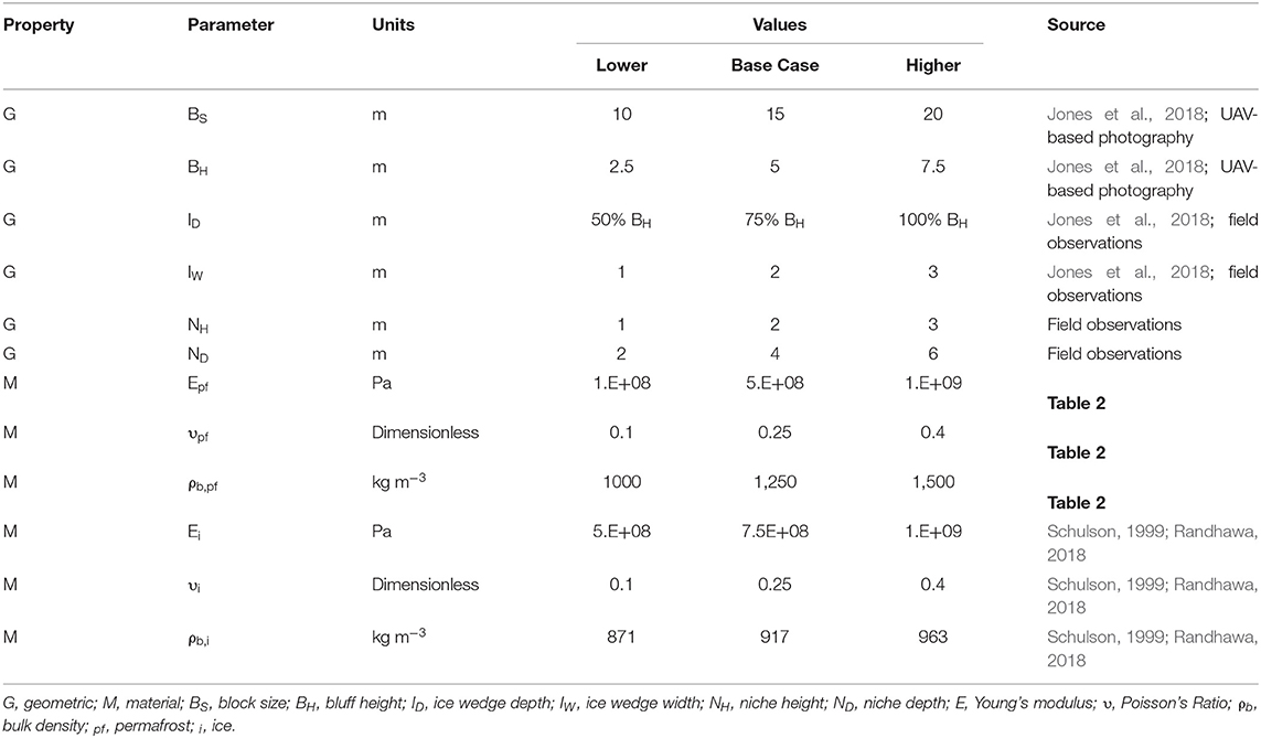
Table 1. Parameter values used to evaluate the impact of variability in geometric and material properties on the magnitude and location of the simulated maximum tensile stress.
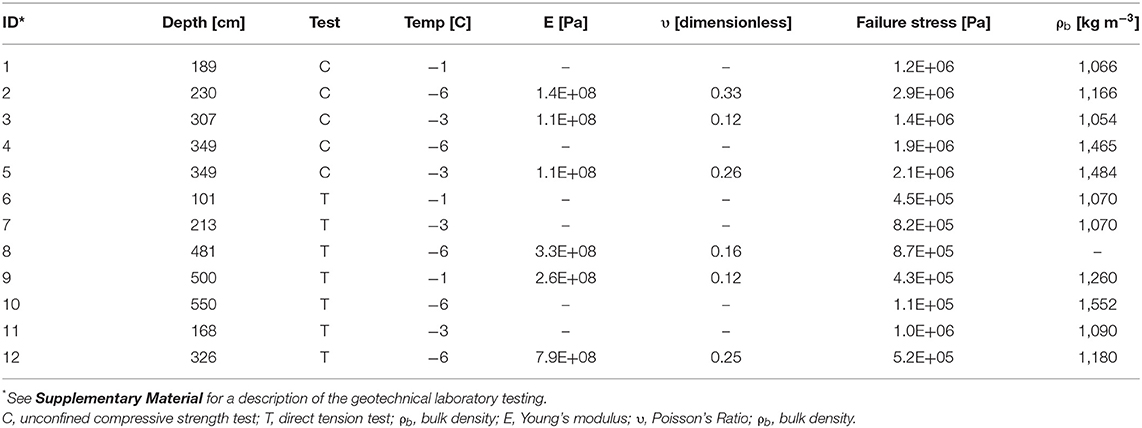
Table 2. Observed permafrost material property values used to inform the parameter ranges in Table 1.
Our initial simulation ensemble targeted variability in geometric characteristics. Here, we constrained our analysis to variability within bounding-type parameter pairs (i.e., niche height vs. niche depth, bluff height vs. permafrost block size, and ice wedge thickness vs. ice wedge depth) to elucidate first-order impacts on the σTmax. Specifically, we simulated all combinations of the low, base case, and high values for each geometric pair to evaluate how the location and magnitude of the σTmax changes across the solution space. We simulated a similar ensemble for the material property pairs (i.e., ice wedge vs. permafrost ρb, E, and υ), and if we did not vary a physical parameter as part of the given pair, we applied the base case values.
After evaluating bulk sensitivities of tensile stress to variability in geometric and material properties, we focused on how niche formation affects the potential failure geometry. We manually advanced (via remeshing) the inland extent of the niche (at 0.5 m increments) for six erosional niche heights ranging from 0.1 to 3 m, tracking the σTmax, as well as the overall shape of the tensile vs. compressive stress fields. At each stage of niche advancement for the simulations, we noted whether or not the σTmax exceeded the lower bound (~100 kPa) tensile strength that was measured in the laboratory (Table 2). Our field observations suggest that once a tension crack forms at the surface, the permafrost bluff material on the ocean-facing side of the crack will eventually topple (Figure 2). Therefore, to compare the potential failure geometry for two end-member scenarios of niche height (i.e., 0.5 and 3 m) for cases where the tensile strength had been met (or exceeded), we drew a line from the point of σTmax to the apex of the niche (Figure 4C) and used this geometry to estimate potential failure areas. This simple failure geometry, which assumes that the failure blocks are rigid, is a reasonable approximation based on our field observations (Figure 2).
To assess how a vertical crack could alter displacement within the vicinity of the potential failure block, we imposed a void in our finite-element mesh that originates at the point of σTmax for the base case simulation scenario and extended it vertically downward. Our hypothetical fracture scenarios include voids that extend laterally in a straight line across a single permafrost block (parallel to the coast) and terminate at the bordering ice wedges, with a constant width (5 cm) and variable fracture depth (0–125 cm; FD). The plan-view geometry of the simulated tension crack approximates conditions that we have observed in the field (Figure 2A). The depths represent 0–25% of the base case BH (5 m). Because our simulations are governed by elastic principles that do not encompass permanent deformation, we focus on how patterns (as opposed to absolute values) of displacement are manifested in the vicinity of the potential failure block in the presence of a fracture.
Results
Our geometric and material property simulation ensembles (Figure 5) indicate that niche characteristics exert the largest impact on the location and magnitude of the σTmax, with the strongest gradient in simulated σTmax following variability in niche depth (ND). The σTmax for our niche pairs ranges from 2.6 to 6.2 m (Δ 3.6 m) inland of the bluff face (Figure 5A) and 29–281 kPa (Δ 252 kPa; Figure 5B). The block size (BS) vs. bluff height (BH) geometric characteristics impose the second greatest impact to the σTmax, which ranges from 3.5 to 6.2 m (Δ 2.7 m) inland of the bluff face (Figure 5A) and 88 to 125 kPa (Δ 37 kPa; Figure 5B). Whereas, BS and BH influence the location of the σTmax, BH dominates the overall impact to the magnitude of the σTmax. Variability in the ice wedge width (IW) and depth (ID) impose ≤1 m and ≤15 kPa of change for the location and magnitude of the σTmax, respectively (Figure 5). The reduction in σTmax for cases of increasing IW and ID reflects an overall stiffening of the bluff in the presence of more massive ice wedge networks. For our simulation scenarios, variability in material properties influences the magnitude of the σTmax. The σTmax ranges from 94 to 139 kPa (Δ 45 kPa), 89 to 126 kPa (Δ 37 kPa), and 112 to 118 kPa (Δ 6 kPa) for the ice wedge vs. permafrost bulk density (ρb), Young's modulus (E), and Poisson's ratio (υ) material pairs (Figure 5B), with sensitivity gradients that are more strongly tied to the permafrost characteristics. The 89–139 kPa (Δ 50 kPa) σTmax range for ρb and E, as opposed to the 112–118 kPa (Δ 6 kPa) σTmax range for υ, highlights the importance of body forces and stiffness (as opposed to differences in lateral vs. axial strain characteristics) for our cantilever-type bluff conditions.
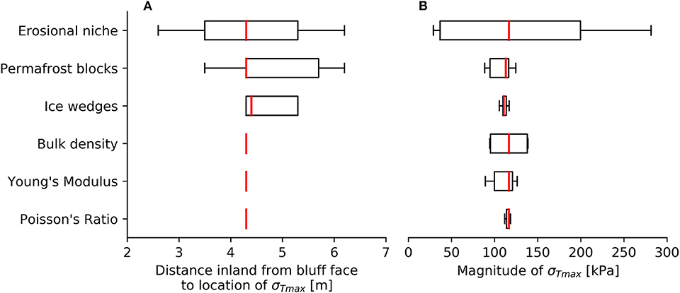
Figure 5. Boxplots showing the impact of variability in geometric (i.e., erosional niche, permafrost block, and ice wedge) characteristics and ice/permafrost material properties (i.e., bulk density, Young's Modulus, and Poisson's Ratio) on the (A) location and (B) magnitude of the simulated maximum tensile stress (σTmax). Geometric and material parameter values are reported in Table 1.
Based on the strong relationship between niche characteristics and σTmax, we conducted geometric simulations with more incremental, quasi-temporal increases in ND (0–10 m) for a wider range of NH values (0.1–3 m; Figure 6). The σTmax for the suite of niche advancement scenarios remain within ~10 kPa of each other up until the ND reaches ~1.5 m (Figure 6A). The tallest and shortest niches (NH = 3 and 0.1 m) exceed our lower bound tensile strength estimate when the ND reaches 3.5 and 4.6 m, respectively (shaded area in Figure 6A). Niche advancement for end-member scenarios of NH reveal systematic differences in the patterns of tensile/compressive stress, as well as the variability in the simulated σTmax. During the advancement of a short (NH = 0.5 m) niche (Figures 6B–D), the σTmax consistently remains inland of the niche and results in a 21.8 m2 potential failure area (Figure 6D). The advancement of the tall (NH = 3 m) niche (Figures 6E–G) results in a considerably smaller, 8.7 m2 potential failure area (Figure 6G). Throughout niche advancement, the shorter niche imparts a deeper and wider zone of tension, reflective of the greater extent of unsupported material. The highest compressive stresses generally coincide with the niche apex (Figure 4), although for the taller (≥3 m) and deeper niches (≥6 m), the maximum compressive stress moved slightly oceanward (up to ~1 m).
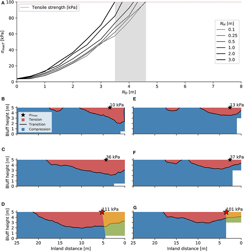
Figure 6. (A) Simulated maximum tensile stress (σTmax) for six niche height (NH) scenarios throughout incremental stages of niche depth (ND) advancement. Snapshots of compressive/tensile stress fields along cross section X-X″ (Figure 3) during niche advancement for the (B–D) short and (E–G) tall niche cases. The stars in (B–G) are the σTmax location, with a red star indicating a value that the σTmax met or exceeded the tensile strength. Yellow shading in (D,G) highlights potential failure areas.
We introduced vertical fractures (FD ranging from 0 to 25% BH) that extend downward from location of the σTmax for our base case scenario (Table 1) to consider the impact of fracture geometries on displacement patterns for our geomechanical simulation framework (Figure 7). We tracked the percent increase in maximum displacement for each FD (Figure 7A). As FD increases, tension is focused near the tip of the fracture and the displacement field transitions from a relatively uniform (along-bluff) pattern to a more concentrated pattern with the maximum displacement located in the section of the bluff face that is directly seaward of the plan-view fracture midpoint (Figures 7B–D). The highest FD (25% BH) produces ~40% more displacement than the lowest FD (0% BH), suggesting that the presence of a tension crack prior to failure can induce localized displacement.
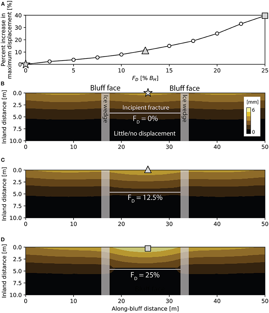
Figure 7. (A) Percent increase in maximum simulated displacement for fracture depth (FD) scenarios ranging from 0 to 25% of the total (5 m) bluff height. The light gray star, triangle, and square symbols correspond to locations in (B–D), respectively. Plan-view perspective of displacement within the vicinity of a fracture with a FD of (B) 0%, (C) 12.5%, and (D) 25%.
Discussion
Cross-Sectional Niche Characteristics
Among the geometric cases that we considered, the σTmax is most sensitive to the cross-sectional niche characteristics (Figure 5). This result is physically consistent, as the niche geometry controls the degree to which the coastal bluff face acts as a cantilever with a bending moment that facilitates toppling mode block failure (Figure 4A). Based on our simulations, which include systematic variations of niche dimension (Figure 6), we found that bluffs with taller and narrower niches should fail in smaller masses compared to those with shorter and deeper niches (Figures 6D,G). Exposure of the bluff face to varying degrees of wave action and surge height is hypothesized to influence niche development (Kobayashi, 1985; Wobus et al., 2011; Ravens et al., 2012; Barnhart et al., 2014b; Hoque and Pollard, 2016). High-intensity, short-duration storm energy may create tall and narrow niches, whereas low-intensity, long-duration storm energy may create short and deep niches. Therefore, an important implication of our work is that the location and shape of the potential failure plane could be modulated by the transient characteristics of the oceanographic forcings (e.g., wave power, water depth, and water temperature) that are delivered to a coastline. This suggests that a stability assessment approach, for which the failure plane is assumed to coincide with a constant geometric feature (e.g., a geologic discontinuity such as an ice wedge) or a particular niche depth, may not be ideal for coastlines similar to our study area. The impact of storm-based metrics (e.g., surge height, dwell time, and water temperature) on niche morphology could be examined with a physics-based modeling approach that expands upon ours to include transient simulations of oceanographic conditions.
Vertical Tension Cracks
A vertical tension crack in a bluff can increase the likelihood of failure because the extent of material available to resist the bending moment prior to toppling has decreased. Whereas ice wedges have been invoked as preferential failure planes for toppling mode block failure (e.g., Hoque and Pollard, 2009, 2016; Barnhart et al., 2014b; Jones et al., 2018), we have observed that failure also occurs along tension cracks in ice wedge polygon centers (Figure 2A). Given laboratory-based estimates of permafrost tensile strength (Table 2), our simulations suggest that tension cracks can form within the range of ND vs. NH that we considered for this study (i.e., 2–6 m and 1–3 m, respectively). For example, the σTmax for a simulation scenario with a 2 m NH and 3.75 m ND exceeds 100 kPa (Figure 6A) within 0.75 m of our field case, which shows a tension crack present for a bluff with a ~1.9 m NH and ~4.5 m ND (Figure 2A). Although the formation and propagation of tension cracks in coastal permafrost bluffs is currently not well-constrained, their presence is important because it signals that some amount of permanent deformation occurs prior to a topple. Neglecting this effect as part of a transient stability assessment approach could result in an underestimate of bluff failure potential.
Thermo-Mechanical Coupling
The numerical experiments that we present here do not include calculations of the thermodynamic state of the permafrost and ice wedge materials. However, the thermodynamic state of permafrost material is important because it determines the amount of frozen and unfrozen water content within the pore space, which has been shown to directly affect bulk mechanical properties (Arenson et al., 2007). In general, unfrozen water content weakens a partially frozen soil, resulting in a strength decrease and the possibility of larger deformations, because the presence of water reduces ice cementation. Fine-grained sediments, such as clays, tend to have the highest unfrozen water content even at temperatures well below the freezing point (Kruse and Darrow, 2017). The thermodynamic state of the permafrost material likely plays a role in niche development via the thermo-abrasion process and, therefore, the bluff geometry, which we have shown to have the largest impact on the location and magnitude of the σTmax. We hypothesize that the time-varying temperature/ice content of the permafrost markedly influences the timing of block failure. Future studies which include tightly coupled thermo-mechanical simulations could improve our ability to resolve the transient nature of the niche formation and quantify the impact of more realistic niche geometries (e.g., tapered wedges) on the stress field. This transient framework could also be used to explore how niche development occurs in the presence of multiple soil types (e.g., coarse- and fine-grained material), internal structures (e.g., sediment warping in the vicinity of ice wedges), and more realistic ice wedge geometries.
Conclusion
We simulated the impacts of variability in coastal permafrost bluff geometry and material properties on stress states leading up to block failure using continuum mechanics theory with static simulations of 3D elastic finite deformation. Our simulation framework tracked the maximum simulated tensile stress (σTmax) that forms along the topographic surface of a permafrost coastal bluff because it is a metric that reflects a likely initiation location for toppling mode block failure. We found that the geometric characteristics of the erosional niche exert the largest impact on the location and magnitude of the σTmax, whereas material properties only influenced the magnitude of the σTmax. Taller and narrower erosional niches promote smaller failure masses compared to those with shorter and deeper niches, suggesting that block failure characteristics could be tied to variations in the intensity and duration of storm energy that interacts with the coastline. We also observe that even relatively shallow vertical cracks can concentrate displacement within ice-bonded permafrost coastal bluffs, highlighting how deformation processes that create non-uniform patterns of displacement may play a role in localizing block failure. Taken together, our geomechanical simulations facilitate new hypothesis-testing regarding the prediction of decadal-scale erosion rates for increasingly dynamic coastal permafrost systems. We propose that developing a tightly coupled thermo-mechanical model to solve heat transfer and finite deformation over the elastic-plastic regime for observed atmospheric/oceanographic conditions is a logical next step to (1) explore more complex geometric characteristics of the basal erosional niche and (2) track the development of tension cracks for coastal permafrost bluffs that are prone to toppling mode block failure. Comprehensive simulations of transient thermal-mechanical response could enable an investigation of stress states that encompass bluff failure.
Data Availability Statement
All datasets generated for this study are included in the article/Supplementary Material.
Author Contributions
The idea for this manuscript arose from discussions between all of the coauthors. MT conducted the simulations and drafted the manuscript. AM developed the mechanical simulation framework. BJ constrained the geometric model inputs with field observations and core sampling. RC constrained the material property model inputs with geotechnical laboratory testing. JF and DB provided valuable input on simulation ensemble design.
Funding
This project was supported by the Laboratory Directed Research and Development program at Sandia National Laboratories and National Science Foundation grants OISE-1927553 and OPP-1745369. Sandia National Laboratories is a multimission laboratory managed and operated by National Technology and Engineering Solutions of Sandia, LLC, a wholly owned subsidiary of Honeywell International Inc., for the U.S. Department of Energy's National Nuclear Security Administration under contract DE-NA0003525.
Conflict of Interest
The authors declare that the research was conducted in the absence of any commercial or financial relationships that could be construed as a potential conflict of interest.
Acknowledgments
Rex Baum, Li Erikson, and two reviewers provided constructive comments on an earlier version of this work. We appreciate thoughtful conversations with Ben Leshchinsky, Sam Johnstone, and Katy Barnhart during the course of this study. Any use of trade, firm, or product names is for descriptive purposes only and does not imply endorsement by the U.S. Government.
Supplementary Material
The Supplementary Material for this article can be found online at: https://www.frontiersin.org/articles/10.3389/feart.2020.00143/full#supplementary-material
References
Aré, F. E. (1988a). Thermal abrasion of sea coasts (part I). Polar Geol. Geol. 12:1. doi: 10.1080/10889378809377343
Aré, F. E. (1988b). Thermal abrasion of sea coasts (part II). Polar Geol. Geol. 12:2. doi: 10.1080/10889378809377352
Arenson, L. U., Springman, S. M., and Sego, D. C. (2007). The rheology of frozen soils. Appl. Rheol. 17, 1–14. doi: 10.1515/arh-2007-0003
Barnhart, K. R., Anderson, R. S., Overeem, I., Wobus, C., Clow, G. D., and Urban, F. E. (2014b). Modeling erosion of ice-rich permafrost bluffs along the Alaskan Beaufort Sea coast. J. Geophys. Res. Earth Surface 119, 1155–1179. doi: 10.1002/2013JF002845
Barnhart, K. R., Overeem, I., and Anderson, R. S. (2014a). The effect of changing sea ice on the physical vulnerability of Arctic coasts. Cryosphere 8, 1777–1799. doi: 10.5194/tc-8-1777-2014
Clement, J. P., Bengtson, J. L., and Kelly, B. P. (2013). Managing for the Future in a Rapidly Changing Arctic. A Report to the President. Washington, DC: Interagency Working Grouping on Coordination of Domestic Energy Development and Permitting in Alaska, 59.
Collins, B. D., and Sitar, N. (2011). Stability of steep slopes in cemented sands. J. Geotech. Geoenviron. Eng. 137, 43–51. doi: 10.1061/(ASCE)GT.1943-5606.0000396
Frederick, J. M., Thomas, M. A., Bull, D. L., Jones, C. A., and Roberts, J. D. (2016). The Arctic Coastal Erosion Problem. Albuquerque, NM: Sandia National Laboratories SAND2016-9762, 122. doi: 10.2172/1431492
Fritz, M., Vonk, J. E., and Lantuit, H. (2017). Collapsing Arctic coastlines. Nat. Clim. Change 7, 6–7. doi: 10.1038/nclimate3188
Gibbs, A. E., Ohman, K. A., Coppersmith, R., and Richmond, B. M. (2017). National Assessment of Shoreline Change: A GIS Compilation of Updated Vector Shorelines and Associated Shoreline Change Data for the North Coast of Alaska, U.S. Canadian Border to Icy Cape. Reston, VA: U.S. Geological Survey. doi: 10.5066/F72Z13N1
Gibbs, A. E., and Richmond, B. M. (2015). National Assessment of Shoreline Change-Historical Shoreline Change Along the North Coast of Alaska, U.S.-Canadian Border to Icy Cape. Reston, VA: U.S. Geological Survey, Open-File Report 2015-1048, 96. doi: 10.3133/ofr20151048
Günther, F., Overduin, P. P., Sandakov, A. V., Grosse, G., and Grigoriev, M. N. (2013). Short- and long-term thermo-erosion of ice-rich permafrost coasts in the Laptev Sea region. Biogeosciences 10, 4297–4318. doi: 10.5194/bg-10-4297-2013
Hoque, M. A., and Pollard, W. H. (2009). Arctic coastal retreat through block failure. Can. Geotech. J. 46, 1103–1115. doi: 10.1139/T09-058
Hoque, M. A., and Pollard, W. H. (2016). Stability of permafrost dominated coastal cliffs in the Arctic. Polar Sci. 10, 79–88. doi: 10.1016/j.polar.2015.10.004
Hughes, Z. (2016). Erosion Threat Are Remote Military Radars Decades Ahead of Schedule. Alaska Public Media. Available online at: https://www.alaskapublic.org/2016/07/04/erosion-threat-at-remote-military-radars-decades-ahead-of-schedule/ (accessed April 30, 2020).
Jones, B. M., Arp, C. D., Jorgenson, M. T., Hinkel, K. M., Schmutz, J. A., and Flint, P. L. (2009). Increase in the rate and uniformity of coastline erosion in Arctic Alaska. Geophys. Res. Lett. 36:L03503. doi: 10.1029/2008GL036205
Jones, B. M., Farquharson, L. M., Baughman, C. A., Buzard, R. M., Arp, C. D., Grosse, G., et al. (2018). A decade of remotely sensed observations highlight complex processes linked to coastal permafrost bluff erosion in the Arctic. Environ. Res. Lett. 13:115001. doi: 10.1088/1748-9326/aae471
Jorgenson, M. T., and Brown, J. (2005). Classification of the Alaskan Beaufort Sea Coast and estimation of carbon and sediment inputs from coastal erosion. Geo Mar. Lett. 25, 1432–1157. doi: 10.1007/s00367-004-0188-8
Kanevskiy, M., Shur, Y., Jorgenson, M. T., Ping, C. L., Michaelson, G. J., Fortier, D., et al. (2013). Ground ice in the upper permafrost of the Beaufort Sea coast of Alaska. Cold Reg. Sci. Technol. 85, 56–70. doi: 10.1016/j.coldregions.2012.08.002
Kobayashi, N. (1985). Formation of thermoerosional niches into frozen bluffs due to storm surges on the Beaufort Sea Coast. J. Geophys. Res. 90, 11983–11988. doi: 10.1029/JC090iC06p11983
Kobayashi, N., and Aktan, D. (1986). Thermoerosion of frozen sediment under wave attack. J. Waterway Port Coastal Ocean Eng. 112, 140–158. doi: 10.1061/(ASCE)0733-950X(1986)112:1(140)
Kruse, A. M., and Darrow, M. M. (2017). Adsorbed cation effects on unfrozen water in fine-grained frozen soil measured using pulsed nuclear magnetic resonance. Cold Reg. Sci. Technol. 142, 42–54. doi: 10.1016/j.coldregions.2017.07.006
Lantuit, H., Overduin, P. P., Couture, N., Wetterich, S., Aré, F., Atkinson, D., et al. (2012). The Arctic coastal dynamics database: a new classification scheme and statistics on Arctic permafrost coastlines. Estuaries Coasts 35, 383–400. doi: 10.1007/s12237-010-9362-6
Larsen, P. H., Goldsmith, S., Smith, O., Wilson, M. L., Strzepek, K., Chinowsky, P., et al. (2008). Estimating future costs for Alaska public infrastructure at risk from climate change. Glob. Environ. Change 18, 442–457. doi: 10.1016/j.gloenvcha.2008.03.005
Loague, K., Heppner, C. S., Ebel, B. A., and VanderKwaak, J. E. (2010). The quixotic search for a comprehensive understanding of hydrologic response at the surface: Horton, Dunne, Dunton, and the role of concept-development simulation. Hydrol. Process. 24, 2499–2505. doi: 10.1002/hyp.7834
Lu, N., Sener-Kaya, B., Wayllace, A., and Godt, J. W. (2012). Analysis of rainfall-induced slope instability using a field of local factor of safety. Water Resour. Res. 48:9524. doi: 10.1029/2012WR011830
Mars, J. C., and Houseknecht, D. W. (2007). Quantitative remote sensing study indicates doubling of coastal erosion rate in past 50 yr along a segment of the Arctic coast of Alaska. Geology 35, 583–586. doi: 10.1130/G23672A.1
Maslanik, J. A., Fowler, C., Stroeve, J., Drobot, S., Zwally, J., Yi, D., et al. (2007). A younger, thinner Arctic ice cover: increased potential for rapid, extensive sea-ice loss. Geophy. Res. Lett. 34:L24501. doi: 10.1029/2007GL032043
Overeem, I., Anderson, R. S., Wobus, C. W., Clow, G. D., Urban, F. E., and Matell, N. (2011). Sea ice loss enhances wave action at the Arctic coast. Geophys. Res. Lett. 38:L17503. doi: 10.1029/2011GL048681
Ping, C., Michaelson, G. J., Guo, L., Jorgenson, M. T., Kanevskiy, M., Shur, Y., et al. (2011). Soil carbon and material fluxes across the eroding Alaska Beaufort Sea coastline. J. Geophys. Res. Biogeosci. 116:G02004. doi: 10.1029/2010JG001588
Randhawa, K. S. (2018). The measurement of the Young's modulus of ice with ultrasonic waves (thesis). Hamburg University of Technology, Hamburg, Germany, 75. doi: 10.15480/882.1656
Rao, S. S. (2007). “Basic equations of elasticity” in Vibrations of Continuous Systems, 2nd Edn, ed S. S. Rao (Hoboken, NJ: John Wiley and Sons, Inc., 700–706.
Ravens, T. M., Jones, B. M., Jinlin, Z., Arp, C. D., and Schmutz, J. A. (2012). Process-based coastal erosion modeling for Drew Point, North Slope, Alaska. J. Waterway Port Coastal Ocean Eng. 138, 122–130. doi: 10.1061/(ASCE)WW.1943-5460.0000106
Reimnitz, E., Graves, S. M., and Barnes, P. W. (1988). Beaufort Sea Coastal Erosion, Shoreline Evolution, and Sediment Flux. Reston, VA: U.S. Geological Survey Miscellaneous Investigations Series, Report I-1182-G, 22. doi: 10.3133/i1182G
Russell-Head, D. D. (1980). The melting of free-drifting icebergs. Ann. Glaciol. 1, 119–122. doi: 10.3189/S0260305500017092
Salinger, A. G., Bartlett, R. A., Bradley, A. M., Chen, Q., Demeshko, I. P., Gao, X., et al. (2016). Albany: using component-based design to develop a flexible, generic multiphysics analysis code. Int. J. Multiscale Comput. Eng. 14, 415–438. doi: 10.1615/IntJMultCompEng.2016017040
Sandia National Laboratories (2017). Sandia's Open Source Software Portal, “Albany.” Available online at: https://software.sandia.gov/drupal/software/ (accessed January 17, 2020).
Schulson, E. M. (1999). The structure and mechanical behavior of ice. J. Miner. Metals Mater. Soc. 51, 21–27. doi: 10.1007/s11837-999-0206-4
Serreze, M. C., Holland, M. M., and Stroeve, J. (2007). Perspectives on the Arctic's shrinking sea-ice cover. Science 315, 1533–1536. doi: 10.1126/science.1139426
Simmonds, I., and Rudeva, I. (2012). The great Arctic cyclone of August 2012. Geophys. Res. Lett. 39:23709. doi: 10.1029/2012GL054259
Stammerjohn, S., Massom, R., Rind, D., and Martinson, D. (2012). Regions of rapid sea ice change: an inter-hemispheric seasonal comparison. Geophys. Res. Lett. 39:L06501. doi: 10.1029/2012GL050874
Thomas, M. A., and Loague, K. (2016). Landscape change as recorded by the Ocean Shore Railroad. Eng. Environ. Geol. 22, 209–223. doi: 10.2113/gseegeosci.22.3.209
U.S. Government Accountability Office (2004). Alaska Native Villages: Villages Affected by Flooding and Erosion Have Difficulty Qualifying for Federal Assistance. Washington, DC: U.S. Government Accountability Office, GAO 04-895T, 17.
U.S. Government Accountability Office (2009). Alaska Native Villages: Limited Progress Has Been on Relocating Villages Threatened by Flood and Erosion. Washington, D.C.: U.S. Government Accountability Office, GAO 09-551, 53.
Vermaire, J. C., Pisaric, M. F. J., Thienpont, J. R., Courtney, M., Colin, J., Kokelj, S. V., et al. (2013). Arctic climate warming and sea ice declines lead to increased storm surge activity. Geophys. Res. Lett. 40, 1386–1390. doi: 10.1002/grl.50191
Vonk, J. E., Sánchez-García, L., van Dongen, B. E., Alling, V., Kosmach, D., Charkin, A., et al. (2012). Activation of old carbon by erosion of coastal and subsea permafrost in Arctic Siberia. Nature 489, 137–140. doi: 10.1038/nature11392
White, F. M., Spaulding, M. L., and Gominho, L. (1980). Theoretical Estimates of Various Mechanism Involved in Iceberg Deterioration in the Open Ocean Environment. Washington, DC: U.S. Coast Guard Technical Service Information Service Publication CG-D-62-8081-20571, 126.
Wobus, C., Anderson, R., Overeem, I., Matell, N., Clow, G., and Urban, F. (2011). Thermal erosion of a permafrost coastline: improving process-cased models using time-lapse photography. Arctic Antarctic Alpine Res. 43, 474–484. doi: 10.1657/1938-4246-43.3.474
Keywords: Arctic Alaska, coastal erosion, permafrost, bluff failure, numerical modeling, mechanics
Citation: Thomas MA, Mota A, Jones BM, Choens RC, Frederick JM and Bull DL (2020) Geometric and Material Variability Influences Stress States Relevant to Coastal Permafrost Bluff Failure. Front. Earth Sci. 8:143. doi: 10.3389/feart.2020.00143
Received: 29 October 2019; Accepted: 17 April 2020;
Published: 12 May 2020.
Edited by:
Felix Ng, University of Sheffield, United KingdomReviewed by:
Sebastian Westermann, University of Oslo, NorwayIrina Overeem, University of Colorado Boulder, United States
Copyright © 2020 Thomas, Mota, Jones, Choens, Frederick and Bull. This is an open-access article distributed under the terms of the Creative Commons Attribution License (CC BY). The use, distribution or reproduction in other forums is permitted, provided the original author(s) and the copyright owner(s) are credited and that the original publication in this journal is cited, in accordance with accepted academic practice. No use, distribution or reproduction is permitted which does not comply with these terms.
*Correspondence: Matthew A. Thomas, bWF0dGhld3Rob21hc0B1c2dzLmdvdg==
†ORCID: Matthew A. Thomas orcid.org/0000-0002-9828-5539