 Zhenxiao Li
 Jiading Wang*
- State Key Laboratory of Continental Dynamics, Department of Geology, Northwest University, Xi’an, China
Several high-fill projects are carried out on the Loess Plateau, China, accompanying the progressive failure of slopes due to excavation. The compelling need requires a deep understanding of variation in the creeping behaviors of intact loess exposed to unloading. A series of creep tests of intact loess were performed under two separated unloading paths: decrease in confining pressure at constant deviator stress and decrease in confining pressure at axial stress. The results demonstrated that axial deformation followed the first unloading path always appears as compression while the three forms of axial deformation followed the second path, depending on the applied axial stress level. At a low unloading stress level, the elongation of axial deformation was observed. At a relatively unloading stress level, the axial deformation of the soil experienced the first elongation and then compression. At a high unloading stress level, the axial deformation appeared as compression, and finally, failure occurred with the increase of the unloading stress level. The failure approach index was introduced to use as the criterion for the loess to transform from stable to accelerated creeping. Finally, a modified Burgers model was proposed to characterize the creeping behavior of intact loess followed unloading paths. There was a good comparison between the calculated and measured data of the soil that establishes the rationality and validity of the proposed model.
Introduction
In recent years, with the rapid economic development, many engineering construction activities have been carried out in the Loess Plateau area, accompanied by a large number of loess slopes subjected to excavation and high-fill projects. Due to the unique physical properties of loess, once improperly disposed of, engineering accidents and damage to the local ecological environment can quickly occur. When soils are subjected to long-term loading, creep deformation increases over time, posing a safety hazard to the actual project. Therefore, the study of creep deformation of loess has tremendous significance for the construction of loess projects. With the rapid development of economic construction, it is necessary to broaden its development space, and then the project of gully control and land construction has been carried out in Yan’an New Area, China. Yan’an New Area is divided into three parts: the North District, the East District, and the West District (Figure 1). The total amount of excavation and filling in the first phase of the construction project in the north district is 363 × 106 m3, and the maximum filling height is 100 m. Due to the difference between the original loess on its sides and bottom and the compacted fill in the middle and upper part, the soil is very easy to produce deformation under the rainfall and long duration loading, which causes foundation deformation and uneven settlement. It is beneficial to alleviate the shortage of land reserve resources in the urban area and is also conducive to protecting the revolutionary sites in the old urban area, promoting the development of the tourism industry, stimulating the healthy and sustainable growth of the economy, and improving the living environment.
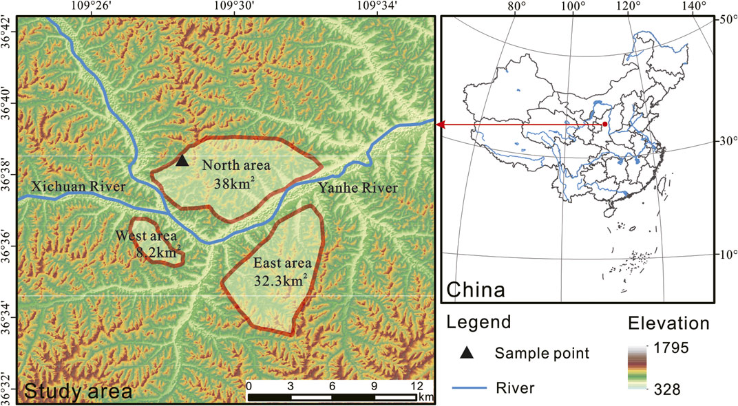
FIGURE 1. Study area and location of soil samples.
Yan’an City is located in the north-central part of the Loess Plateau and belongs to the hilly and gully area of the Loess Plateau. Quaternary Aeolian loess is exposed in the area, mainly loess hills and gullies. The terrain in the area is high in the west and low in the east, with some uplifts in the central part and relatively large ups and downs in the north relative to the south. The geomorphology can be divided into the valley stage area and the loess beam area according to the geomorphic unit. Landforms can be divided into river landforms and loess landforms according to their genesis, and loess landforms can be subdivided into loess erosion landforms, submerged landforms, gravity landforms, and accumulation landforms. Due to the uplift of the stratum (Late Pleistocene-Holocene) in the Loess Plateau, more water systems and valleys were formed, and the erosion effect of water flow (tracing erosion, lateral erosion, and down erosion) continued to reshape the landform, leading to forming a comprehensive landscape with undulating terrain and ravines.
The excavation process is also the unloading process of the soil, and its deformation characteristics have unique laws. The traditional soil mechanics theory uses conventional triaxial test (loading test) parameters to calculate the slope deformation. This stress path is completely different for the slope excavation unloading stress path and cannot truly reflect the unloading process of the slope excavation. For example, due to excavation, some parts of the surrounding stratum have stress relaxation and rebound deformation, while other parts have stress concentration and compression or shear deformation, which changes the pore density. Due to the complexity of the problem, the current experimental research and theoretical analysis on the deformation and failure mechanism of the soil under unloading are not perfect. Therefore, it is necessary to strengthen the research on the unloading characteristics of the soil, a more comprehensive understanding of the deformation and failure mechanism of the soil under unloading state, providing the theoretical basis and reasonable calculation parameters for the calculation of soil deformation under unloading.
During slope excavation, the stress paths of the soil at different parts of the slope are completely different. In order to correctly simulate the stress path in excavation engineering, several kinds of typical stress paths are abstracted from the soil at different parts of the slope during the excavation process, carrying out unloading tests that simulate the slope excavation process. And there are relatively few studies on the creep behavior of soil under the unloading path. For excavated slopes, the unloading path is more consistent with the actual working conditions, and the creep behavior of the soil under the unloading path should be studied. In order to accurately simulate the change of the soil stress path during the slope excavation process, the drainage conditions during the test must first be determined. The slope excavation project should adopt a fast excavation method, the water in the outer soil body will not be discharged, and it is approximately regarded as an undrained process.
Excavation of slope is a typical excavation unloading problem. In slope excavation, the soil will exhibit different mechanical properties when it goes through different unloading paths from the same stress state. Therefore, it is necessary to carry out a creep test of soil under different unloading stress paths. In recent years, through long-term monitoring of landslides and other data, most landslides have creeping behavior (Sasaki et al., 2000; Mansour et al., 2011; Di Maio et al., 2013, 2015; Wen and Jiang, 2017). As creep accumulates in the soil of the most sensitive slip zone of the landslide, it may eventually trigger a large-scale slip of the slope under the action of external factors (Pytharouli and Stiros, 2010). It is recognized that the recent human casualties and property damage in loess areas are closely related to the creep behavior of landslides (Sun et al., 2016; Palmer, 2017). The porous structure and well-developed vertical cracks of loess contribute to the unique creep properties of loess (Tan and Yang, 1988; Derbyshire, 2001; Zhang et al., 2014; Zhou et al., 2014; Peng et al., 2015; Xu and Coop, 2016; Xu et al., 2018). Many researchers have analyzed the creep behavior of soils. Xin et al. (2016) conducted a kinematic analysis of large-scale landslides on the Loess Plateau in Baoji, China, and concluded that creep movements in the slip zone predispose to landslides. Yates et al. (2018) conducted a statistical analysis of landslides caused by loess creep in Canterbury, New Zealand, and found that loess landslides with creep behavior are mainly controlled by the liquid behavior of saturated loess, potential failure surfaces, and seasonal wetting/drying cycles. Wang et al. (2020) analyzed the creep behavior of loess at different water contents and proposed a modified Burgers model that accurately describes the accelerated creep stage curves. Xie et al. (2018) found that the creep behavior of loess is closely related to microstructural changes. Among them, elemental models are widely used in loess soils. Zhou et al. (2016) conducted creep tests under different confining pressure and temperature conditions and established a rate-dependent constitutive model for frozen loess. Tang et al. (2020) conducted triaxial creep tests using a rheological triaxial test apparatus and proposed a dual-element creep model to describe the creep process of loess. Zhu et al. (2014) investigated the creep properties of red-layer slip zone soils under different vertical loading and water content conditions through direct shear creep tests. In addition, many scholars have also achieved many results in the experimental study of the creep behavior of different geotechnical materials (LO PRESTI, 1996; Gasc-Barbier et al., 2004; Fabre and Pellet, 2006; Wang et al., 2014, 2015; Ye et al., 2015; Yu et al., 2015; Zheng et al., 2015). Although scholars have studied the strength of loess extensively, research on the creep properties of loess has been relatively limited. The progress of creep test on loess is mainly based on loading principal stress in steps under constant confining pressure. There is rarely research on unloading confining pressure creep test under different stress paths, while for the actual engineering construction of filling and excavation process, the surrounding soil is in the state of cyclic unloading and loading relative to the stress state before mining.
The mechanical properties of soils under unloading stress paths from different perspectives have been analyzed. Li and Kong (2019) analyzed the creep properties of Nanyang expansive soil under different levels of deviator stress by unloading creep tests and proposed a nonlinear four-element model to describe the creep deformation of soil. Yang et al. (2020) conducted an undrained unloading test to analyze the effects of different unloading stress paths and unloading rates on the mechanical properties of the Tianjin blowing soil and proposed a prediction formula for soil damage strength considering these two factors. Mei et al. (2010) pointed out that the shear strength parameters of the soil under different unloading paths were significantly different. Zhen et al. (2008). analyzed the stress-strain curve of clay soil, based on triaxial unloading tests under K0 consolidation undrained and pointed out that its initial tangential modulus is proportional to the soil consolidation perimeter pressure.
Furthermore, some researchers have also constructed creep models based on empirical, yielding surfaces, and damage effects (Sivasithamparam et al., 2015; Chang et al., 2020). For loess, creep models have been proposed, based on the results of triaxial creep tests and theoretical analysis (Li et al., 2011), and there are four creep models, including Cam–Clay model, Duncan–Chang model, Kelvin model, and Burgers model (Graham et al., 2001; Liu and Carter, 2002; Nguyen et al., 2011; Wan et al., 2011). Among these creep models, the Burgers model is widely used to describe the creep behavior of various rocks and soils due to its intuitive concept, clear parameters and physical implications, and simple calculations. However, in the Burgers model, the deformation of the loess followed unloading paths is generally not considered, and the compelling need requires a modified Burgers model to characterize the creeping behavior of the loess followed unloading paths.
The objectives of this work are to understand the creep behavior of intact loess followed the unloading path. The unloading creep tests with constant principal stress and deviator stress are carried out on undisturbed Malan loess. The creep deformation characteristics of the undisturbed Malan loess under the two stress paths were analyzed. The failure approach index was introduced to evaluate the degree of soil damage during the unloading creep test. An improved Burgers model was proposed by connecting a nonlinear dashpot element in series with the Burgers model and combining the functional relationship between the viscoelastic modulus and creep behavior.
Sample and Test Methods
Sample Preparation
The loess specimen was taken from the construction site of Yan’an New Area, which belongs to the late Pleistocene loess (Q3, Malan loess), and the coordinates of the sampling point are N36°45′13.5″, E109°11′4.2″. To prevent the soil from being affected by the external environment (frost, rainfall, sunshine), excavate 0.5 m horizontally before sampling, and avoid disturbing the soil. After removal, soil samples were marked top-bottom, then quickly sealed by wrapping with cling film, and subsequently wrapped with bubble film to avoid soil disturbance during transportation. Soil samples were placed in a dry and ventilated place after being transported back to the room to avoid direct sunlight.
The liquid limit of the soil was 27.9%, and the plastic limit was 18.6%, as determined by the LG-100D combined liquid-plastic limit tester. Using the compaction test, the optimum moisture content and maximum dry density of loess in the study area were measured as 16.3% and 1.82 g/cm3, respectively (Table 1).
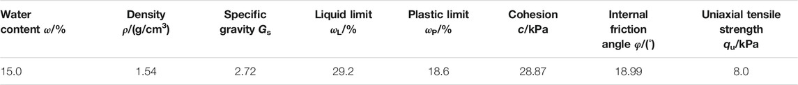
TABLE 1. Physical and mechanical properties of soil in the study area.
Testing Programs
The three groups of the creep tests were performed by following unloading paths to investigate the creep behavior of intact loess. The first groups involved unloading the confining pressure in steps with constant deviator stress. The
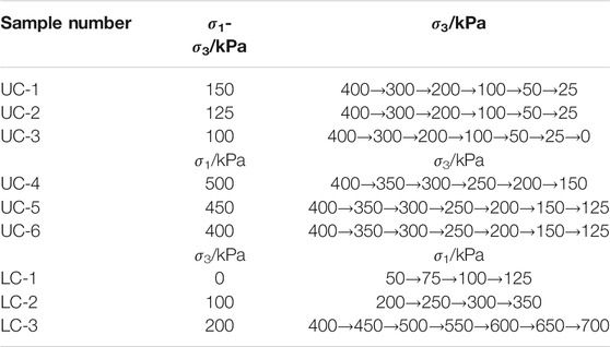
TABLE 2. Loading and unloading programs.
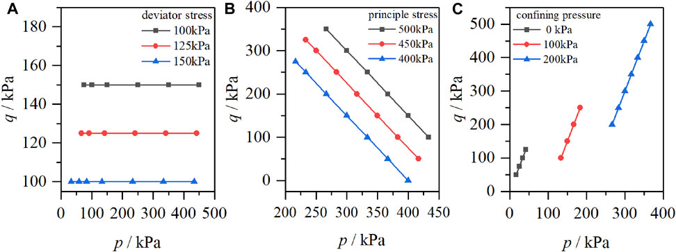
FIGURE 2. Stress path of the testing program.
Testing Method
The equipment selected for this creep test is the FSR-20 triaxial creep meter for unsaturated soil. The instrument mainly consists of a pressurization system, data acquisition system, and air compressor. The maximum axial load that the equipment can provide is 2,000 kPa, the maximum pore air pressure is 500kPa, the maximum axial deformation that can be measured is 18 mm, and the volume deformation is 50 cm3. For the preparation of undisturbed loess triaxial creep type samples: take out the cling film-wrapped loess original soil sample, determine the upper and lower position of the soil sample, cut it flat and place it in the triaxial chipper, and cut the soil sample into a cylinder of 61.8 mm diameter (Figure 3).
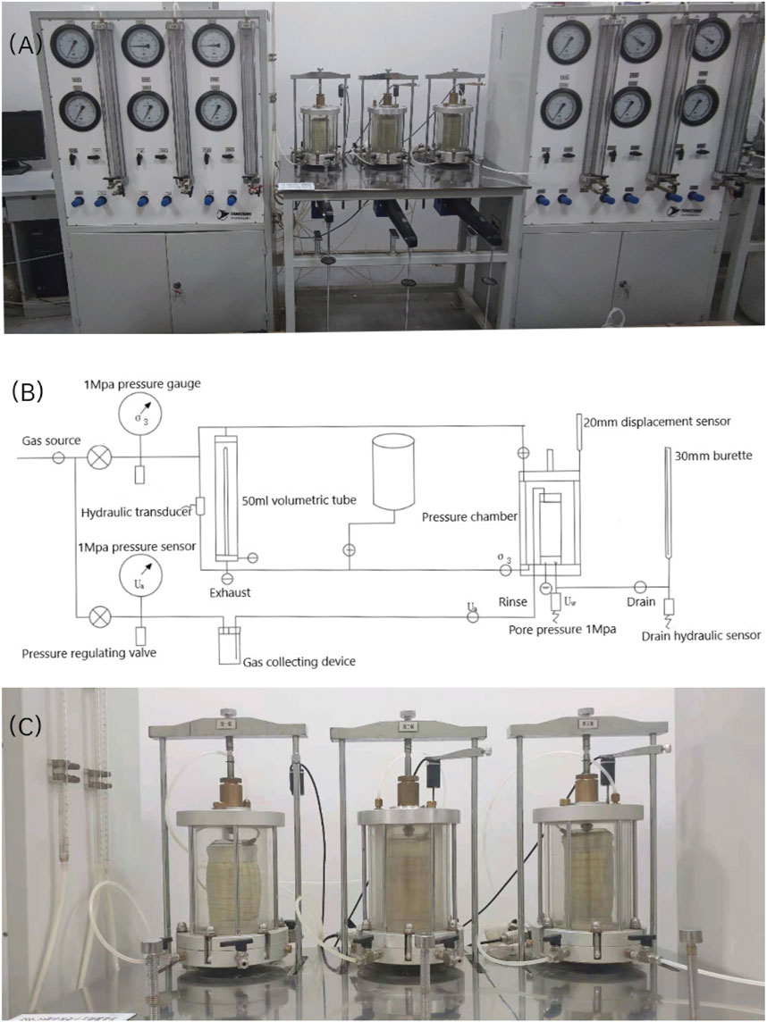
FIGURE 3. (A) FSR-20 Unsaturated Soil Triaxial Creep Apparatus. (B) Schematic diagram of creep apparatus. (C) Creep experiment.
The unloading stress path of slope excavation can be generally simplified into three paths (Figure 4). The first unloading path is the stretching path, and it can be considered that the horizontal load decreases while the vertical load remains unchanged under the limit condition; the second unloading path is a triaxial shearing path, which shows that the horizontal and vertical loads are unloaded at the same time, and it can be considered that the partial stress remains unloaded under the limit condition; the third unloading path is the direct shearing path, which corresponds to the bottom area in Figure 4 and can be considered as vertical unloading and transverse unloading. Comprehensive existing research, most of the current research on unloading characteristics is based on direct shearing path, and the reduction of vertical load while the lateral load remains unchanged generally does not cause damage to the soil, so this article focuses on zone stretching and triaxial shearing path.
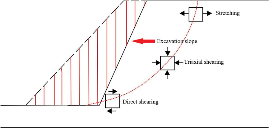
FIGURE 4. Sketch map of unloading stress paths.
Testing Results
Unloading the Confining Pressure in Steps With Constant Deviator Stress
Assuming that the soil is mainly deformed in elasticity at the beginning of unloading, the deformation law of the axial strain of the soil during the unloading process can be analyzed according to the linear elasticity theory. For the first type of triaxial creep test with constant deviator stress, the axial strain
According to the generalized Hooke’s law, as the unloading stress level increases (the confining pressure
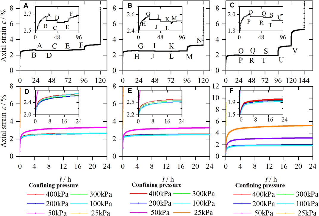
FIGURE 5. Strain-time curves of samples, (A) UC-1, (B) UC-2, (C) UC-3, and creep curves of samples, (D) UC-1, (E) UC-2, (F) UC-3.
Figures 5A–C show the strain-time curves of deviator stress under the control of 150, 125, and 100 kPa, respectively. Figures 5D–F are obtained according to the Boltzmann superposition principle. As can be seen from Figure 4, the axial strain variation of unloading confining pressure in steps under different deviator stresses is similar, which is manifested in three forms of deformation. As shown in Figures 5A,D, the variation of axial strain is slight at the initial unloading stage, the confining pressure is gradually unloaded from 400 kPa to 300 kPa, and the axial strain decreases (shown as axial elongation, corresponding to the ABD section in Figure 5A, which is the same as the above analysis results based on the generalized Hooke’s law. When the confining pressure is unloaded from 300 kPa to 200 kPa, the axial strain decreases at the moment of unloading (shown as axial elongation) and gradually increases over time (axial compression, corresponding to the DCE section in Figure 5A). When the confining pressure is unloaded from 100 kPa to 50 kPa, the axial strain increases significantly (shown as axial compression, corresponding to the EF section in Figure 5A), and noticeable creep occurs. With the further increase of unloading stress level, the soil samples show an accelerated creep stage, and the soil is damaged.
By comparing Figures 5A–C, it can be seen that the unloading stress points of soil under the above three deformation forms are different under different deviator stresses. The curve segments ABD, GHIJK, and OPQRSTU showed axial elongation deformation; the curve segments DCE and KLM showed axial elongation deformation followed by axial compression deformation; and the curve segments EF, MN, and UV showed axial compression deformation. When the deviator stress is 100 kPa, the second deformation form does not appear, and the axial elongation deformation is directly transformed into axial compression deformation.
The reason for the above phenomenon is that, at the initial stage of unloading the confining pressure, the soil can be considered to be in an elastic deformation stage, which corresponds to the first deformation form (axial extension) mentioned above; as the level of unloading stress increases, tiny cracks appear inside the soil, and the deformation of the soil gradually changes from elastic deformation to plastic deformation, which corresponds to the second form of deformation (first axial extension and then axial compression); with the further increase of the unloading stress level, the internal micro-cracks of the soil are penetrated, and the deformation of the soil is mainly plastic deformation, which corresponds to the third form of deformation (axial compression).
Unloading the Confining Pressure in Steps With Constant Principal Stress
Refer to the analysis in the previous section, assuming that the soil is mainly elastically deformed in the initial stage of unloading, so the deformation law of the axial strain of the soil during the unloading confining pressure can be analyzed according to the linear elasticity theory. For the second type of triaxial creep test with constant principal stress, the axial strain
According to the generalized Hooke’s law, as the unloading stress level increases (the confining pressure decreases), the axial strain increases (shown as axial compression).
Figures 6A–C show the strain-time curves when the first principal stress is controlled at 500kPa, 450 kPa, and 400 kPa, respectively. Figures 6D,E,F are obtained according to the Boltzmann superposition principle. It can be seen from Figure 6 that the axial strain of the unloading confining pressure under different
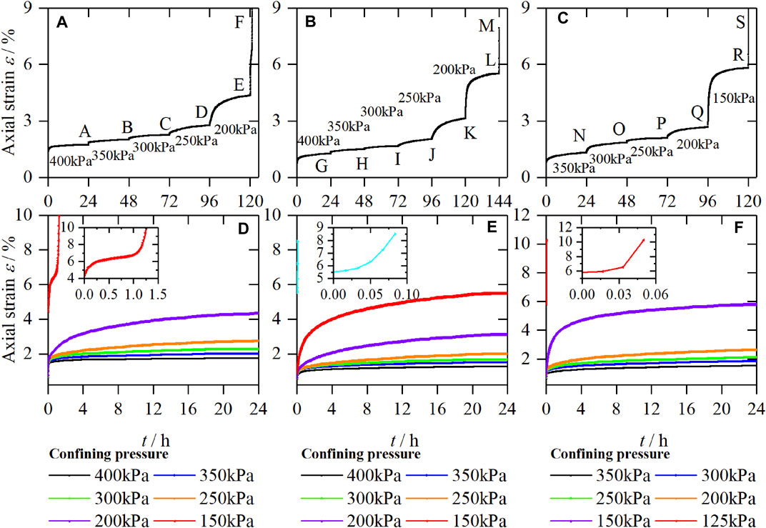
FIGURE 6. Strain-time curves of samples, (A) UC-4 (B) UC-5, (C) UC-6, and creep curves of samples, (D) UC-4, (E) UC-5, (F) UC-6.
Analyzing the above reasons, it can be seen that removing the confining pressure
Loading the Principal Pressure in Steps With Constant confining Pressure
Under different confining pressures and different deviator stress, the creep curves of loess all show prominent creep deformation characteristics: first is instantaneous deformation, then deformation at the decaying creep stage, and the deformation at the stable creep stage. The loess is dominated by instantaneous deformation under the deficient deviator stress level (generally the first deviator stress level). The instantaneous deformation of the soil occurs at the moment of loading, and with the increase of time, a tiny creep deformation occurs. With the increase of time, the creep deformation rate gradually decreases, and approaching zero, the creep curve shows the decay type. Under a higher deviator stress level, the loess first produces instantaneous deformation. As time increases, its creep deformation rate decreases, gradually approaching a specific value greater than zero, and the creep curve presents a steady flow type. Under high deviator stress levels, the deformation rate of loess increases rapidly, and the soil is damaged. Under the same confining pressure, the greater the deviator stress, the greater the instantaneous deformation of loess, the more severe the creep deformation, and the more significant the creep effect. Increasing deviator stress under constant confining pressure, referring to the analysis in the former section, and assuming that the soil is predominantly deformed elastically at the beginning of loading, the deformation pattern of the axial strain in the soil during the increase of the first principal stress can be analyzed according to the theory of linear elasticity (Figure 7).
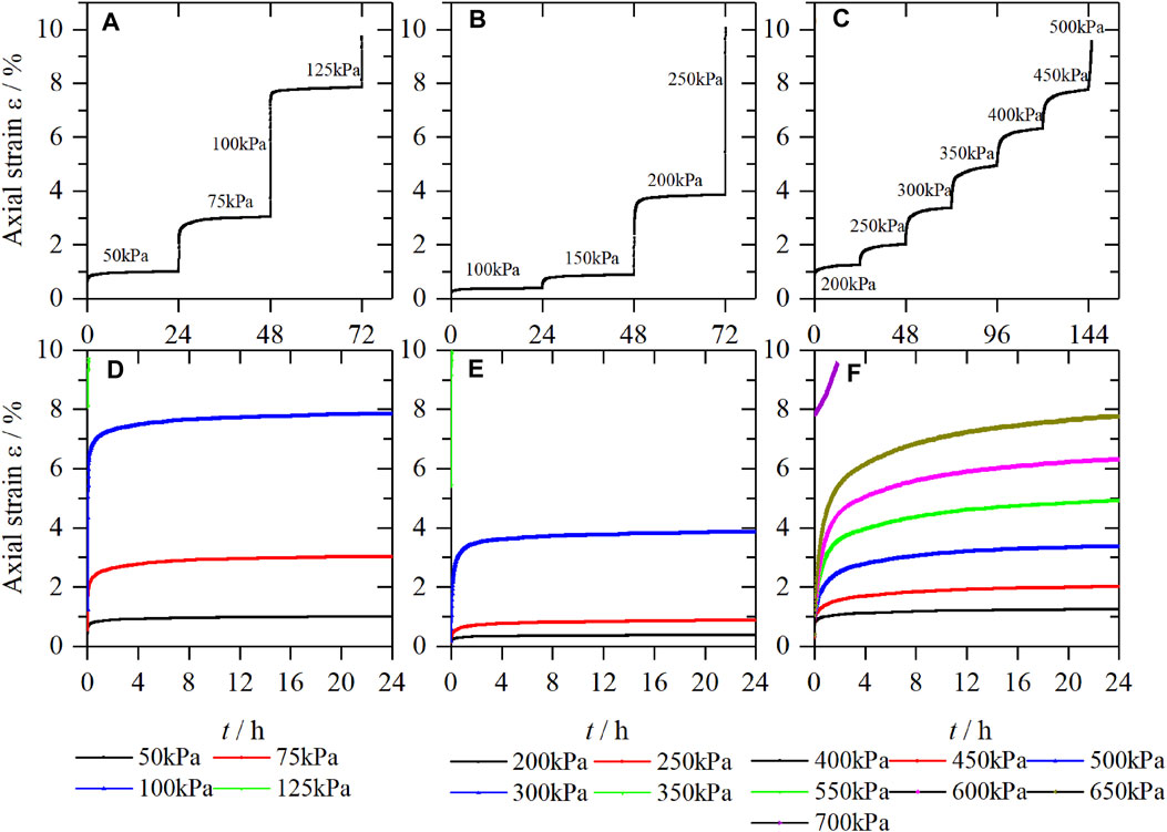
FIGURE 7. Strain-time curves of samples, (A) LC-1 (B) LC-2, (C) LC-3, and creep curves of samples, (D) LC-1, (E) LC-2, (F) LC-3.
Results Analysis
By analyzing the test curves, when keeping the principal stress and the deviator stress constant, the creep test law of soil unloading confining pressure is different. Unloading the confining pressure in steps with constant principal stress, the axial deformation shows an increasing trend (manifested as axial compression). Unloading the confining pressure in steps with constant deviator stress, when the unloading stress level is low, the axial deformation will show a decreasing trend (shown as axial elongation); while the unloading stress level is high, it will first decrease and then increase (shown as the first axial elongation and then axial compression). When the loading stress level is higher, it shows an increasing trend (shown as axial compression).
Both unloading methods will damage the soil, but their stress paths are not the same. Unloading the confining pressure in steps with constant principal stress, the axial deformation of the soil has been increasing and the change rule is obvious, which is suitable for studying the unloading creep characteristics of the soil. Unloading the confining pressure in steps while keeping the deviator stress constant, according to the different unloading levels, the variation law of axial deformation presents three forms. The transition stress state points of the first deformation form (axial elongation) and the second deformation form (axial elongation followed by axial compression) can be used to distinguish the elastic deformation from the plastic deformation.
In order to describe the dangerous degree of the stress state of the soil under different stress loading paths, this article analyzes the damage proximity based on the Mohr-Coulomb strength criterion, where the parameters are as shown in Eqs 5–9:
The failure approach index R refers to the state function of soil material damage, and its value range is (0, 1). When R=0, the stress point is on the yield surface, and the soil yields; when R=1, the stress point is in a three-dimensional isostatic stress state, which is relatively safe.
The creep test curves of UC-1, UC-2, and UC-3 are analyzed by the failure approach index. Figure 8A shows the failure approach analysis of each soil sample under different stress states. Comparing Figure 5 and Figure 8A, it can be seen that when R > 0.4, unloading the confining pressure in steps while keeping the deviator stress constant will only cause the soil to produce axial tension; when 0.1 < R < 0.4, the soil has obvious creep deformation; when R < 0.1, the soil has an accelerated creep stage, the axial deformation of the soil increases rapidly, and the soil is damaged. Similarly, the creep test curves of UC-4, UC-5, and UC-6 are analyzed by the failure approach index. Comparing Figure 6 and Figure 8B, it can be seen that when R > 0.4, the confining pressure is removed while principal stress remains unchanged, and only a small axial deformation is generated in the soil. When 0.1 < R < 0.4, the axial deformation of soil increases obviously. When R < 0.1, the soil shows accelerated creep stage.
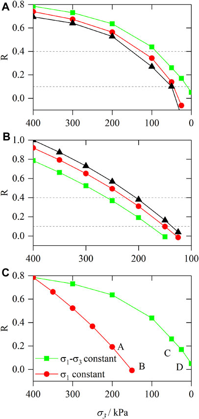
FIGURE 8. (A) Comparison of R under different deviator stress. (B) Comparison of R under different principal stress. (C) Comparison of R in different stress paths.
Based on the above analysis, it can be seen that when R < 0.4, the soil gradually changes from elastic deformation to plastic deformation; when R < 0.1, the soil enters the accelerated creep stage. Therefore, the failure approach index R = 0.4 can be used as the critical value to distinguish between elastic deformation and plastic deformation; use R = 0.1 as the critical value to distinguish the stable creep stage and accelerated creep stage of the soil.
Discussion
This study found that the creep characteristics of soil are different under different stress paths. When principal stress is constant, the deviator stress increases gradually under unloading confining pressure, and the soil exhibits prominent creep characteristics, which is consistent with the creep behavior of soil under the stress path of increasing deviator stress in steps when confining pressure is constant; however, when deviator stress is constant, the soil exhibits different creep characteristics under unloading confining pressure. The reason is that when the unloading stress level is low, the stress state of the soil is far away from the Mohr-Coulomb failure surface. At this time, the application of deviator stress only causes the relative dislocation among the soil particles, and the internal structure of the soil is reorganized and balanced, so when the unloading stress is low, the soil only shows axial elongation; with the increase of the unloading stress, the stress state of the soil gradually approaches the Mohr-Coulomb failure surface. At this time, the lateral limit of the soil decreases, and the soil particles are easy to move around, resulting in tiny cracks in the soil. The macroscopic performance is lateral swelling and axial compression, so when the unloading stress is high, the soil will be firstly elongated and then compressed. With the further increase of the unloading stress level, the internal cracks of the soil are penetrated, and the axial deformation rapidly increases, which leads to the destruction of the soil. Therefore, when the unloading stress level is higher, the soil directly shows axial compression.
With the gradual increase of the axial strain caused by unloading, it is accompanied by the adjustment of the soil structure. Micro-cracks are weak structural planes in loess, and the unloading effect causes loess to have a tendency to expand along the cracks, and the cracked planes are softened, resulting in a certain deformation of the soil along with the cracked planes, and serious damage to the integrity of the soil sample. Under the same axial strain, the existence of cracks magnifies the unloading damage effect at the same axial strain. In the same way, When the principal stress remains and unloading the confining pressure, due to the simultaneous axial and radial action, microcrack generation and expansion are stronger than other stress paths, and damage and degradation effects are relatively enhanced.
Figure 8C shows the comparison of the closeness of soil damage under two stress paths (
The path of unloading confining pressure stress with constant principal stress can be considered as stepwise increasing deviator stress is superimposed on the stress path of unloading confining pressure with constant deviator stress, and the removed confining pressure ∆
Comparative Analysis of Different Stress Paths for Loading
The loading and unloading experiments under different stress paths are unloading the confining pressure with constant deviator stress and loading the deviator stress with constant confining stress. Align the following three comparisons: the relationship of mean net stress and deviator stress, strain-time curves, and double logarithmic curves of strain time. Observe the law of curve change and draw the following conclusions.
Comparing the curves under different stress paths, it can be seen that the strain-time curve is obviously non-linear; the shape of the curve is roughly similar before the soil is damaged, showing an attenuation stable type (hyperbolic type). From the strain-time diagrams of the two stress paths when the soil sample reaches the confining pressure of 0 kPa and the axial pressure of 100 kPa (Figures 8E, 9C), it can be seen that unloading the confining pressure in steps with constant deviator pressure will destroy first compared to loading deviator pressure in steps with constant confining pressure. Meanwhile, from the strain-time diagrams of the two stress paths when the soil sample reaches the confining pressure of 400 kPa and the deviator stress of 100 kPa (Figures 8F, 9D, it can be seen that loading the axial pressure with constant confining pressure will cause more deformation. This is because the soil has accumulated a certain deformation in the case of deviator pressure of 100 kPa and confining pressure of 400 kPa. It shows that in the stress path of unloading the confining pressure with constant deviator stress, the deformation is not as obvious as in the stress path of increasing the deviator pressure with constant confining pressure, due to the accumulation of internal damage, loading (unloading) to the same stress state, and unloading the confining pressure state of the soil damage required for the minor deviator stress.
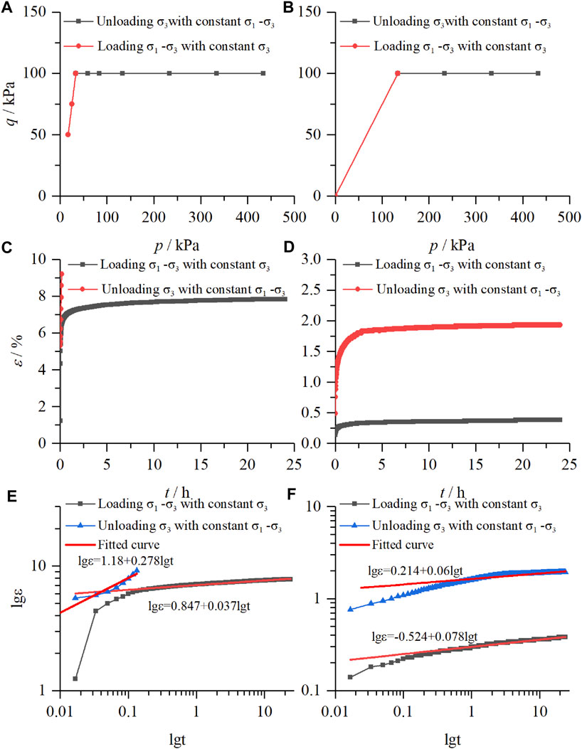
FIGURE 9. Comparison of unloading the confining pressure in steps with constant deviator stress and loading the deviator stress in steps with constant confining pressure, (A) (B) the relationship of mean net stress and deviator stress, (C) (D) strain-time curves, (E) (F) double logarithmic curves of strain time.
Meanwhile, use the same method to compare the unloading experiments of the following two stress paths: unloading the confining pressure with constant deviator stress and principal stress. The following conclusions can be drawn from comparing the relationship of mean net stress and deviator stress, strain-time curves, and double logarithmic curves of strain time.
Form the strain-time diagrams of the two stress paths when the soil sample reaches the confining pressure of 300kPa and the principal stress of 450 kPa (Figures 9E, 10C, the curve shows that the deformation of unloading confining pressure with constant deviator stress is immense; meanwhile, the following steady-state creep rate is low, it is due to the fact that the unloading confining pressure with constant deviator stress has accumulated a certain amount of deformation in the initial state, and the creep deformation is evident in this case. The curves (Figures 9F, 10D) reach another final stress via the same stress path (
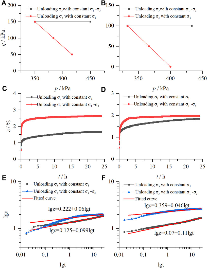
FIGURE 10. Comparison of unloading the confining pressure in steps with constant deviator stress and unloading the confining pressure in steps with constant principal stress, (A) (B) the relationship of mean net stress and deviator stress, (C) (D) strain-time curves, (E) (F) double logarithmic curves of strain time.
Constitutive Model
Analysis of the results of the unloading confining pressure in steps creeping test with constant principal stress shows the following:
1) At each stress level, the soil sample produces instantaneous strain, and the value increases with enhancing the unloading stress level.
2) When the unloading level is low, the soil sample goes through the decay creep phase and the stable creep phase (its stable creep rate is close to 0).
3) When the unloading stress level is high, the soil goes through the decay creep phase and the stabilization creep phase and then enters the accelerated creep phase; eventually, the soil is destroyed.
The complete creep curve of soil sample includes decay creep phase, stable creep phase, and accelerated creep phase; Burgers model can describe the decay creep phase and stable creep phase of soil well. However, because the elements in the Burgers model are linear elements, the accelerated creep phase of the soil cannot be described. The whole process of creep deformation is the process of gradual cracking and damage accumulation inside the soil until the crack propagation is destroyed. Therefore, a parameter can be introduced to characterize the microstructure change of the soil due to irreversible deformation until failure. Considering that the stress-strain relationship often loses its one-to-one correspondence after the soil enters the nonlinear characteristic, and the creep deformation of the soil is irreversible, the strain parameter can be chosen to indicate whether the soil enters the accelerated creep phase and a nonlinear accelerated dashpot Liu et al. (2018) is introduced to describe the deformation of the soil in the accelerated creep phase, as shown in Figure 11A. The stress-triggered means, the nonlinear viscous pot is rigid when the strain generated by the model is less than
where
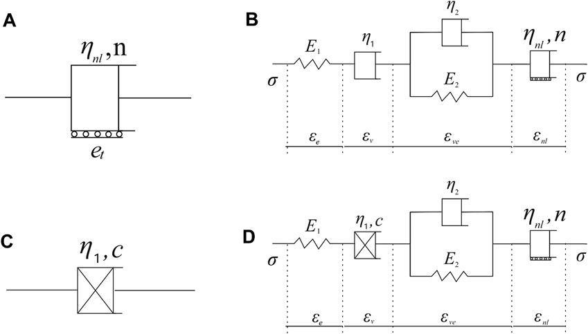
FIGURE 11. (A) Nonlinear accelerated dashpot. (B) Improved Burgers component model. (C) Nonlinear accelerated dashpot. (D) Improved Burgers component model.
Based on the previous analysis on the failure approach index of soil, when R < 0.1, the soil enters the accelerated creep stage. Therefore, classify whether the soil enters the accelerated creep stage according to R.
Based on the above analysis, the improved Burgers component model for the loading creep process of the high-fill loess in this area is shown in Figure 11B, and the total strain and differential form of the constitutive equation of this model can be expressed as follows:
1) when
2) When
Under the action of constant stress
1) When
2) When
3) When
Carry out Laplace inverse transformation on Eqs 13–15 to obtain the creep constitutive equation:
According to the research on the viscosity coefficient in soil creep, the viscosity coefficient is the attenuation function of stress and an increasing function of time. The nonlinear formula of the viscosity coefficient is
Figure 1(C) is the constitutive equation shown by the nonlinear viscous element constructed by the above formula.
In order to avoid mathematical problems on the derivation of nonlinear creep model from former research Xia et al. (2011), the above equation can be obtained:
The nonlinear dashpot element is used to replace the
Fit the creep test curves under the four stress states of A, B, C, and D in Figure 8A, Figure 12 is the fitting results under different stress paths, and Table 3 is fitting parameters.
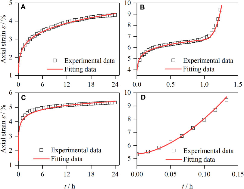
FIGURE 12. Fitting curve of unloading confining pressure in steps with constant principal stress. (A) Stress state at point A. (B) Stress state at point B. (C) Stress state at point C. (D) Stress state at point D.
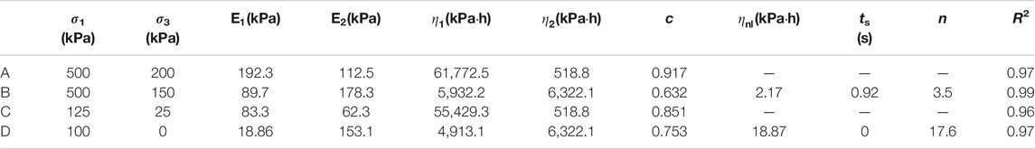
TABLE 3. Fitting parameters.
The fitted results in Figure 12 and the fitted data in Table 3 show that the theoretical values of the improved Burgers model are in good agreement with the experimental results. It not only fully reflects the instantaneous elastic deformation of the soil after loading but also reflects the initial creep of the first stage and the stable creep of the second stage; especially, the model overcoming the traditional linear element model cannot describe the difficulty of the accelerated creep stage, and the deformation of the accelerated creep stage of the soil is successfully fitted. The result is significantly better than the traditional Burgers model. Since accelerated creep is the key stage of slope failure prediction, the successful description of the accelerated creep stage by this model shows that it has a certain guiding significance for slope failure prediction.
Conclusion
In this article, the undisturbed Malan loess from Yan’an is taken as the research subject, and the unloading creep tests are carried out to analyze the creep deformation characteristics of undisturbed Malan loess under different stress paths by progressively unloading confining pressure in steps under constant principal stress and constant deviator stress; the conclusions are as follows:
1) Under the two unloading stress paths, the axial deformation of soil is different. Under constant
2) By introducing the concept of the failure approach index, the stress state of the soil under the two unloading stress paths and the degree of near failure of the soil can be well described. The failure approach index R=0.4 can be used as the critical value for distinguishing between elastic deformation and plastic deformation, and R=0.1 is used as the critical value for distinguishing between the stable creep stage and the accelerated creep stage of the soil.
3) By comparing the failure approach index of the soil under the two stress states, it is found that the failure approach index R of unloading confining pressure when the principal stress
4) The Burgers model is widely used to describe the creep behavior of soils due to its intuitive concept, clear parameters, physical implications, and simple calculations. By connecting a nonlinear dashpot element in series with the Burgers model and combining the functional relationship between the viscoelastic modulus and creep behavior. It can be concluded that the improved Burgers model proposed in this article has higher relevant results and can more accurately describe the creep characteristics under different unloading stress paths by comparing the modeling results to the testing results.
Data Availability Statement
The original contributions presented in the study are included in the article/Supplementary Material; further inquiries can be directed to the corresponding author.
Author Contributions
ZL is responsible for experimental design and conduct and article writing. JW and DZ are responsible for providing theoretical guidance and article revision.
Funding
This research was supported by the National Natural Science Foundation of China (grant numbers 42027806 and 41630639) and the National Key Research and Development Plan (grant number 2018YFC1504703).
Conflict of Interest
The authors declare that the research was conducted in the absence of any commercial or financial relationships that could be construed as a potential conflict of interest.
Publisher’s Note
All claims expressed in this article are solely those of the authors and do not necessarily represent those of their affiliated organizations, or those of the publisher, the editors, and the reviewers. Any product that may be evaluated in this article, or claim that may be made by its manufacturer, is not guaranteed or endorsed by the publisher.
References
Chang, Z., Gao, H., Huang, F., Chen, J., Huang, J., and Guo, Z. (2020). Study on the Creep Behaviours and the Improved Burgers Model of a Loess Landslide Considering Matric Suction. Nat. Hazards 103, 1479–1497. doi:10.1007/s11069-020-04046-0
Derbyshire, E. (2001). Geological Hazards in Loess Terrain, with Particular Reference to the Loess Regions of China. Earth-Science Rev. 54, 231–260. doi:10.1016/S0012-8252(01)00050-2
Di Maio, C., Scaringi, G., and Vassallo, R. (2015). Residual Strength and Creep Behaviour on the Slip Surface of Specimens of a Landslide in marine Origin clay Shales: Influence of Pore Fluid Composition. Landslides 12, 657–667. doi:10.1007/s10346-014-0511-z
Di Maio, C., Vassallo, R., and Vallario, M. (2013). Plastic and Viscous Shear Displacements of a Deep and Very Slow Landslide in Stiff clay Formation. Eng. Geology. 162, 53–66. doi:10.1016/j.enggeo.2013.05.003
Fabre, G., and Pellet, F. (2006). Creep and Time-dependent Damage in Argillaceous Rocks. Int. J. Rock Mech. Mining Sci. 43, 950–960. doi:10.1016/j.ijrmms.2006.02.004
Gasc-Barbier, M., Chanchole, S., and Bérest, P. (2004). Creep Behavior of Bure Clayey Rock. Appl. Clay Sci. 26, 449–458. doi:10.1016/j.clay.2003.12.030
Graham, J., Tanaka, N., Crilly, T., and Alfaro, M. (2001). Modified Cam-Clay Modelling of Temperature Effects in Clays. Can. Geotech. J. 38, 608–621. doi:10.1139/t00-125
Li, D.-W., Fan, J.-H., and Wang, R.-H. (2011). Research on Visco-Elastic-Plastic Creep Model of Artificially Frozen Soil under High Confining Pressures. Cold Regions Sci. Technology 65, 219–225. doi:10.1016/j.coldregions.2010.08.006
Li, J. J., and Kong, L. W. (2019). Creep Properties of Expansive Soil under Unloading Stress and its Nonlinear Constitutive Model. Rock Soil Mech. 40, 3465–3473. doi:10.16285/j.rsm.2018.2306
Liu, K. Y., Xue, Y. T., and Zhou, H. (2018). Study on 3D Nonlinear Visco-Elastic -plastic Creep Constitutive Model with Parameter Unsteady of Soft Rock Based on Improved Bingham Model. Rock Soil Mech. 39, 4157–4164. doi:10.16285/j.rsm.2017.0572:
Liu, M. D., and Carter, J. P. (2002). A Structured Cam Clay Model. Can. Geotech. J. 39, 1313–1332. doi:10.1139/t02-069
Lo Presti, D. C. F. (1996). Rate and Creep Effect on the Stiffness of Soils. Measuring And Modeling Time Dependent Soil Behavior. Geotech. Spec. Publ. 61, 166–180.
Mansour, M. F., Morgenstern, N. R., and Martin, C. D. (2011). Expected Damage from Displacement of Slow-Moving Slides. Landslides 8, 117–131. doi:10.1007/s10346-010-0227-7
Mei, G. X., Chen, H., Lu, T. H., and Yin, Z. Z. (2010). Research on Lateral Stress-Strain Relation on Side of Foundation Pit with Lateral Unloading. Chin. J. Rock Mech. Eng. 29, 3108–3112.
Nguyen, S. T., Dormieux, L., Pape, Y. L., and Sanahuja, J. (2011). A Burger Model for the Effective Behavior of a Microcracked Viscoelastic Solid. Int. J. Damage Mech. 20, 1116–1129. doi:10.1177/1056789510395554
Palmer, J. (2017). Creeping Earth Could Hold Secret to Deadly Landslides. Nature 548, 384–386. doi:10.1038/548384a
Peng, J., Fan, Z., Wu, D., Zhuang, J., Dai, F., Chen, W., et al. (2015). Heavy Rainfall Triggered Loess-Mudstone Landslide and Subsequent Debris Flow in Tianshui, China. Eng. Geology. 186, 79–90. doi:10.1016/j.enggeo.2014.08.015
Pytharouli, S. i., and Stiros, S. c. (2010). Kinematics and Rheology of a Major Landslide Based on Signal Analysis. Géotechnique 60, 207–222. doi:10.1680/geot.8.P.049
Sasaki, Y., Fujii, A., and Asai, K. (2000). “Soil Creep Process and its Role in Debris Slide Generation-Field Measurements on the north Side of Tsukuba Mountain in Japan,” in In Developments In Geotechnical Engineering Engineering Geological Advances in Japan for the New Millennium. Editors Y. Kanaori, K. Tanaka, and M. Chigira (Elsevier), 199–219. doi:10.1016/S0165-1250(00)80017-6
Sivasithamparam, N., Karstunen, M., and Bonnier, P. (2015). Modelling Creep Behaviour of Anisotropic Soft Soils. Comput. Geotechnics 69, 46–57. doi:10.1016/j.compgeo.2015.04.015
Sun, M., Tang, H., Wang, M., Shan, Z., and Hu, X. (2016). Creep Behavior of Slip Zone Soil of the Majiagou Landslide in the Three Gorges Area. Environ. Earth Sci. 75, 1199. doi:10.1007/s12665-016-6002-x
Tan, R. Y., and Yang, C. H. (1988). Structural Responses of Underground Pipelines to Dynamic Loadings. Mech. Structures Machines 16, 103–122. doi:10.1080/08905458808960255
Tang, H., Duan, Z., Wang, D., and Dang, Q. (2020). Experimental Investigation of Creep Behavior of Loess under Different Moisture Contents. Bull. Eng. Geol. Environ. 79, 411–422. doi:10.1007/s10064-019-01545-8
Wan, L. H., Cao, P., Huang, Y. H., Wang, Y. X., and Zhang, X. Y. (2011). Creep Test of Hard Rock and Modified Generalized Kelvin Creep Model. Amm 90-93, 626–632. doi:10.4028/www.scientific.net/AMM10.4028/www.scientific.net/amm.90-93.626
Wang, G., Zhang, L., Zhang, Y., and Ding, G. (2014). Experimental Investigations of the Creep-Damage-Rupture Behaviour of Rock Salt. Int. J. Rock Mech. Mining Sci. 66, 181–187. doi:10.1016/j.ijrmms.2013.12.013
Wang, J.-a., Wang, Y.-x., Cao, Q.-j., Ju, Y., and Mao, L.-t. (2015). Behavior of Microcontacts in Rock Joints under Direct Shear Creep Loading. Int. J. Rock Mech. Mining Sci. 78, 217–229. doi:10.1016/j.ijrmms.2015.05.002
Wang, X., Wang, J., Zhan, H., Li, P., Qiu, H., and Hu, S. (2020). Moisture Content Effect on the Creep Behavior of Loess for the Catastrophic Baqiao Landslide. CATENA 187, 104371. doi:10.1016/j.catena.2019.104371
Wen, B.-P., and Jiang, X.-Z. (2017). Effect of Gravel Content on Creep Behavior of Clayey Soil at Residual State: Implication for its Role in Slow-Moving Landslides. Landslides 14, 559–576. doi:10.1007/s10346-016-0709-3
Xia, C. C., Jin, L., and Guo, R. (2011). Nonlinear Theoretical Rheological Model for Rock a Review and Some Problems. Chin. J. Rock Mech. Eng. 30, 454–463.
Xie, X., Qi, S., Zhao, F., and Wang, D. (2018). Creep Behavior and the Microstructural Evolution of Loess-like Soil from Xi'an Area, China. Eng. Geology. 236, 43–59. doi:10.1016/j.enggeo.2017.11.003
Xin, P., Liang, C., Wu, S., Liu, Z., Shi, J., and Wang, T. (2016). Kinematic Characteristics and Dynamic Mechanisms of Large-Scale Landslides in a Loess Plateau: a Case Study for the north Bank of the Baoji Stream Segment of the Wei River, China. Bull. Eng. Geol. Environ. 75, 659–671. doi:10.1007/s10064-015-0824-8
Xu, L., and Coop, M. R. (2016). Influence of Structure on the Behavior of a Saturated Clayey Loess. Can. Geotech. J. 53, 1026–1037. doi:10.1139/cgj-2015-0200
Xu, L., Coop, M. R., Zhang, M., and Wang, G. (2018). The Mechanics of a Saturated Silty Loess and Implications for Landslides. Eng. Geology. 236, 29–42. doi:10.1016/j.enggeo.2017.02.021
Yang, A. W., Yang, S. K., and Zhang, Z. D. (2020). Experimental Study of Mechanical Properties of Dredger Fill under Different Unloading Rates and Stress Paths. Rock Soil Mech. 41, 2891–2900+2912. doi:10.16285/j.rsm.2019.1992
Yang, W. D., Zhang, Q. Y., and Chen, F. (2011). Research on Nonlinear Rheological Model of Debase and Treatment for Creep Loading History. Chin. J. Rock Mech. Eng. 30, 1405–1413.
Yates, K., Fenton, C. H., and Bell, D. H. (2018). A Review of the Geotechnical Characteristics of Loess and Loess-Derived Soils from Canterbury, South Island, New Zealand. Eng. Geology. 236, 11–21. doi:10.1016/j.enggeo.2017.08.001
Ye, G.-l., Nishimura, T., and Zhang, F. (2015). Experimental Study on Shear and Creep Behaviour of green Tuff at High Temperatures. Int. J. Rock Mech. Mining Sci. 79, 19–28. doi:10.1016/j.ijrmms.2015.08.005
Yu, H. D., Chen, W. Z., Gong, Z., Tan, X. J., Ma, Y. S., Li, X. L., et al. (2015). Creep Behavior of Boom clay. Int. J. Rock Mech. Mining Sci. 76, 256–264. doi:10.1016/j.ijrmms.2015.03.009
Zhang, F., Wang, G., Kamai, T., and Chen, W. (2014). Effect of Pore-Water Chemistry on Undrained Shear Behaviour of Saturated Loess. Q. J. Eng. Geology. Hydrogeology 47, 201–210. doi:10.1144/qjegh2013-085
Zhen, G., Yan, Z. X., Lei, H. Y., and Wang, P. (2008). Experimental Studies on Unloading Deformation Properties of Silty clay of First marine Layer in Tianjin Urban Area. Rock Soil Mech. 5, 1237–1242. doi:10.16285/j.rsm.2008.05.058
Zheng, H., Feng, X.-T., and Hao, X.-j. (2015). A Creep Model for Weakly Consolidated Porous sandstone Including Volumetric Creep. Int. J. Rock Mech. Mining Sci. 78, 99–107. doi:10.1016/j.ijrmms.2015.04.021
Zhou, Y. F., Tham, L. G., Yan, R. W. M., and Xu, L. (2014). The Mechanism of Soil Failures along Cracks Subjected to Water Infiltration. Comput. Geotechnics 55, 330–341. doi:10.1016/j.compgeo.2013.09.009
Zhou, Z., Ma, W., Zhang, S., Du, H., Mu, Y., and Li, G. (2016). Multiaxial Creep of Frozen Loess. Mech. Mater. 95, 172–191. doi:10.1016/j.mechmat.2015.11.020
Keywords: creep behaviors, unloading paths, failure approach index, constitutive model, intact loess
Citation: Li Z, Wang J and Zhang D (2021) Creep Behavior of Intact Loess Followed Unloading Paths. Front. Earth Sci. 9:744864. doi: 10.3389/feart.2021.744864
Received: 21 July 2021; Accepted: 25 August 2021;
Published: 20 September 2021.
Edited by:
Fanyu Zhang, Lanzhou University, ChinaReviewed by:
Zhiwei Zhou, University of Chinese Academy of Sciences, ChinaRubén Galindo, Polytechnic University of Madrid, Spain
Copyright © 2021 Li, Wang and Zhang. This is an open-access article distributed under the terms of the Creative Commons Attribution License (CC BY). The use, distribution or reproduction in other forums is permitted, provided the original author(s) and the copyright owner(s) are credited and that the original publication in this journal is cited, in accordance with accepted academic practice. No use, distribution or reproduction is permitted which does not comply with these terms.
*Correspondence: Jiading Wang, d2FuZ2ppYWRpbmcwMjlAMTYzLmNvbQ==