 Xinglong Zhao
 Bingxiang Huang
 Giovanni Grasselli
- 1State Key Laboratory of Coal Resources and Safe Mining, China University of Mining and Technology, Xuzhou, China
- 2Department of Civil and Mineral Engineering, University of Toronto, Toronto, ON, Canada
Fracturing induced by disturbing stress of hydraulic fracturing is the frontier common core scientific problem of reservoir stimulation of coal bed methane and shale gas. The finite-discrete element method, numerical calculation method, is used to analyze the basic law of shear failure and tension failure of natural fractures induced by the disturbing stress of the hydraulic fracture. The simulation results show that when natural fractures and other weak structures exist on the front or both sides of hydraulic fracture, the shear stress acting on the surface of natural fracture will increase until the natural fracture failure, which is caused by the disturbing stress of hydraulic fracturing. The seepage area on the front and both sides of the hydraulic fracture did not extend to the natural fracture while the natural fracture failure occurred. It indicates that the shear failure of natural fractures is induced by the disturbing stress of hydraulic fracturing. When the hydraulic fracture propagates to the natural fracture, the hydraulic tension fracture and disturbed shear fractures are connected and penetrated. As the fluid pressure within the natural fracture surface increases, the hydraulic fracture will continue to propagate through the natural fracture. Meanwhile, due to the action of fluid pressure, a tensile stress concentration will occur at the tip of the natural fracture, which will induce the airfoil tension failure of the natural fracture. With the increase of the principal stress difference, the range of the disturbing stress area and the peak value of the disturbing stress at the front of the hydraulic fracture tip increase, as well as the shear stress acting on the natural fracture surface. During the process of hydraulic fracture approaching natural fracture, the disturbing stress is easier to induce shear failure of natural fracture. With the increase of the cohesive force of natural fracture, the ability of natural fractures to resist shear failure increases. As the hydraulic fracture approaches natural fractures, the disturbing stress is more difficult to induce shear failure of natural fracture. This study will help to reveal the formation mechanism of the fracture network during hydraulic fracturing in the natural fractures developed reservoir.
Introduction
Hydraulic fracturing technology was first applied to the development of oil and gas wells to improve the flow capacity of fluids in oil and gas reservoirs. It is a key measure for increasing the production of oil and gas wells with broad application prospects. At present, it is also the main reservoir stimulation technology for oil and natural gas exploitation (Burrows et al., 2020; Liu et al., 2020; Zhang et al., 2020). In order to achieve sufficient gas flow rates in shale gas, tight gas, tight oil, and coalbed methane wells, it is usually necessary to perform hydraulic fracturing to improve the permeability of the reservoir. In recent years, it has been widely used in the coal industry. Significant results have been achieved in the use of hydraulic fracturing technology for hard roof control, hard top coal weakening, coal seam permeability improvement, coal and gas outburst prevention, and rock burst prevention (Huang et al., 2015; Huang et al., 2016; Huang et al., 2017).
In the process of hydraulic fracturing, with the initiation and propagation of hydraulic fractures, the magnitude and distribution of stress around the hydraulic fractures also change. It is called the “stress disturbance” effect of hydraulic fracturing, which is known as the “stress shadow” effect in the oil industry (Roegiers and Bennaceur, 1990; Cheng, 2007). The stress caused by the stress disturbance effect of hydraulic fracturing is called disturbing stress.
There are complex natural fractures in the coal seam, including joints, bedding, and cleats. These naturally developed weak structural planes together form the natural fracture network structure of the coal seam. When hydraulic fracturing is performed in the coal seam with developed natural fractures, the disturbing stress of hydraulic fracturing will induce the natural fractures breaking around the hydraulic fractures, that is, the fracturing effect induced by disturbing stress of hydraulic fracturing. The practice of hydraulic fracturing in underground coal seams with shock tendency shows that the process of hydraulic fracturing weakens the coal strength to prevent shock which may be accompanied by “coal cannon.” The position of the coal cannon is not necessarily exactly the same as the position of the hydraulic crack (Zhao, 2019) (Figure 1). It shows that the fractures formed during the hydraulic fracturing process not only include the fractures generated under the action of water pressure but also include the ruptures of natural fractures induced by the disturbing stress of hydraulic fracturing.
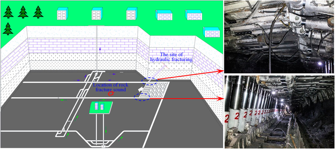
FIGURE 1. Position of “coal cannon” during hydraulic fracturing in underground coal mines.
Many studies have been done on the interaction between natural cracks and artificial cracks. Related experimental research results show that the propagation of hydraulic fractures becomes very irregular due to the interference of natural fractures. The existence of natural fracture media causes a large amount of fluid loss, which induce the main hydraulic fracture to propagate along the natural fractures (Chen et al., 2008; Yang et al., 2012; Chen et al., 2013; Hu and Ghassemi, 2021). These studies are all aimed at the object that high-pressure water drives the natural fractures to open and extend after the hydraulic fractures propagate to natural fractures and high-pressure water enters the natural fractures. There is no research involving the break of the natural fractures induced by the disturbing stress of hydraulic fracturing.
Based on the author’s previous study of the stress disturbance of hydraulic fracturing, this paper focuses on the disturbing stress of hydraulic fracturing inducing the break of natural fractures around the hydraulic fracture. The combined finite-discrete element method (FDEM) numerical calculation is utilized to analyze the basic law of shear failure and tension failure of natural fractures induced by the disturbing stress on the front and both sides of hydraulic fractures during the hydraulic fracturing process.
The fracturing induced by disturbing stress of hydraulic fracturing is a common and core scientific problem in the fracturing of coalbed methane, shale gas, and dry hot rock. The fractures caused by the disturbing stress are a component of the fracture network during fracturing in the natural fractures developed reservoir. The fractures induced by the disturbing stress and the hydraulic fractures together form a fracture network structure. Studying the fracturing effect induced by disturbing stress of hydraulic fracturing will help to reveal the formation mechanism of the fracture network during hydraulic fracturing in the natural fractures developed reservoir. The research result will provide a more comprehensive theoretical basis for determining the fracturing technology and parameters of coalbed methane and shale gas reservoirs.
FDEM Numerical Calculation Principle
FDEM is a numerical method originally developed by Munjiza et al. It allows dynamic simulation of the interaction between multiple objects. The simulated object can be a single complete domain or a complete domain composed of a group of discrete bodies. During the simulation process, these objects can undergo elastic deformation, translation, rotation, interaction, and fracture when the rupture criterion is met, thereby generating new discrete bodies. Then, the newly created object can move further, interact, deform, and fracture. FDEM can well simulate the transition from continuous to discontinuous behavior in rock masses. It combines the advantages of finite element method (FEM) in describing elastic deformation and the ability of discrete element method (DEM) to capture discontinuities. Finite element method (FEM) is used to deal with material deformation and the process of evaluating material failure. Discrete element method (DEM) is used to detect new contacts and deal with the translation, rotation, and interaction of discrete bodies (Munjiza et al., 1995; Munjiza and Andrews, 1998; Munjiza et al., 1999; Munjiza and Andrews, 2000; Munjiza and John, 2002). Therefore, the FDEM method can effectively realize the hydraulic fracturing simulation of coal and rock mass.
The Basic Principle of FDEM
In FDEM, the continuum is discretized into three-node triangular elements and four-node cohesive elements with no thickness initially embedded on the common side of adjacent triangular elements (Figure 2). The constant strain linear elastic triangle element is used to capture the elastic deformation of the material. The failure of the inelastic crack element is used to simulate the initiation and propagation of fractures in the continuum (Munjiza, 2004).
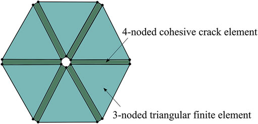
FIGURE 2. The continuum was discretized using cohesive elements interspersed throughout a mesh of triangular elements.
Control Equation
The triangular element updates the displacement and velocity of the node according to the unbalanced force of the node according to Newton’s second law. The generalized motion control equation can be expressed as follows (Lisjak and Grasselli, 2014):
where M and C are the system mass and damping matrix, respectively; x is the nodal displacement vector; and
Material Damage and Failure Modes
Nonlinear fracture mechanics is used to simulate the failure process of materials. When the stress in the front area of the fracture tip reaches the tensile strength of the material, a fracture process zone is formed at the front of the fracture tip (FPZ) (Figure 3A). The material force in this region exhibits nonlinear behavior. Although the material in the fracture process zone FPZ has been damaged, it can still transmit the load to the fracture wall (Lisjak et al., 2017). In FDEM, assuming that the fracture surface coincides with the edge of the triangular element, the fracture process zone is characterized by the four-node bond fracture element (Figure 3B).
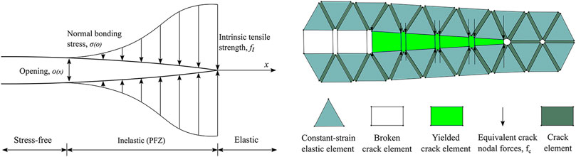
FIGURE 3. (A) Fracture process zone (FPZ) and (B) Numerical characterization in FDEM.
According to the local stress and deformation fields, the fracture unit will yield and fail. There are three failure modes, namely, Mode I tensile failure, Mode II shear failure, and mixed Mode I-II composite failure (Geomechanica Inc, 2018; Liu et al., 2018) (Figure 4).
(1) Mode I tensile failure: before the fracture initiates, the stress at the fracture tip has a linear relationship with the opening between the two triangular elements. When the opening
(2) Mode Ⅱ shear failure: the tangential cohesive force between triangular elements is a function of slip distance and normal stress (Figure 4B). When the tangential slip distance
where
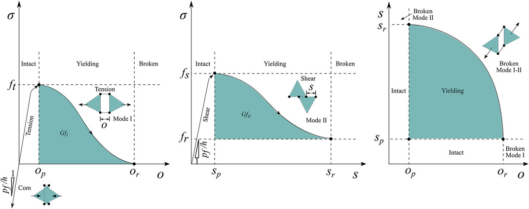
FIGURE 4. The failure modes in FDEM. (A) Mode I tensile failure; (B) Mode II shear failure; (C) mixed Mode I-II failure.
When the fracture slip distance is greater than the critical slip distance
where
(3) Mixed Mode I-II failure: in addition to pure tension failure and pure shear failure, the fracture unit will also have a mixed failure of two failure modes. Therefore, the coupling failure criterion of Mode I tensile failure and Mode II shear failure is defined (Figure 4C):
where
The residual opening distance
The Hydraulic-Mechanical Coupling Principle in FDEM
When FDEM is used to simulate hydraulic fracturing, fluid pressure is applied at the injection node. The nodal force as the external load is calculated by Eq. 1. After hydraulic fracturing, a fluid flow channel is created through the interface between adjacent triangular finite elements. The Darcy’s law and parallel plate cube law are utilized to calculate the fluid flow process in the flow channel. The fluid pressure at the nodes of the fracture network is updated to drive the continuous propagation of the fractures (Labuz et al., 1985; Liu et al., 2018).
The hydraulic-mechanical coupling analysis in FDEM adopts a two-way explicit coupling analysis method. Iterative sequential solution is performed through data exchange between the mechanical solver and the hydraulic solver. The calculation of the mechanical field is affected by the fluid pressure between the internal cells. Meanwhile, due to the deformation and destruction of the solid, the calculation of the fluid field is affected by the opening between the finite elements.
FDEM Numerical Model Design
The disturbing stress concentration areas in the process of hydraulic fracture propagation are mainly distributed in the front of the fracture tip and on both sides of the main fracture. Therefore, two situations will be analyzed by two cases. Case 1 is the opening and propagation of natural fractures in front of the hydraulic fractures tip induced by disturbing stress. Case 2 is the opening and propagation of natural fractures on both sides of the hydraulic fractures induced by disturbing stress. The size of the numerical model is 60 m × 60 m.
Case 1: Disturbing Stress at the Front of Hydraulic Fractures Induces Natural Fractures to Open and Propagate
Numerical Model
An inclined natural fracture is set up in the direction of hydraulic fracture propagation in case 1. The length of the natural fracture is 23 m, and the distance from the hydraulic fracturing injection point is 27 m. When the hydraulic fractures are approaching natural fractures, the failure process of natural fractures induced by the disturbing stress at the front of the hydraulic fracture tip will be analyzed (Figure 5).
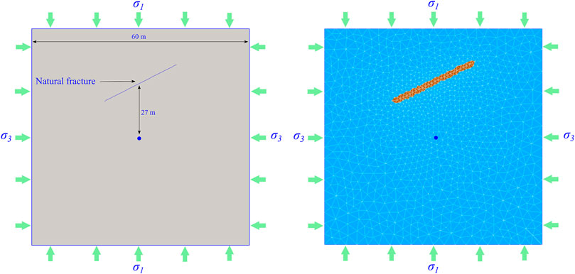
FIGURE 5. Numerical model for case 1. (A) Geometry model; (B) meshing.
Simulation Scheme and Parameter Setting
The numerical simulation scheme of case 1 is shown in Table 1. The influence of principal stress difference and natural fracture cohesion on the failure of natural fractures in the process of hydraulic fracture approaching natural fracture will be mainly studied. The fluid bulk modulus is 5 × 10⁷ Pa, and the kinematic viscosity is 1.004 × 10⁻⁶ m2/s. The pump rate is 0.3 L/s. The input parameters of the model are shown in Table 2.
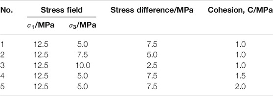
TABLE 1. Numerical simulation program for case 1.
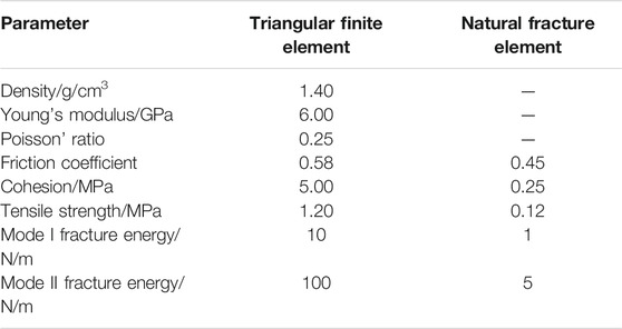
TABLE 2. The input parameter for FDEM model for case 1.
Case 2: Disturbing Stress on Both Sides of Hydraulic Fractures Induces Natural Fractures to Open and Propagate
Numerical Model
Two inclined natural fractures are set up on both sides of the hydraulic fracture propagation direction, respectively, in case 2. The length of the natural fracture is 5.6 m, and the distance from the hydraulic fracturing injection point is 6 m (Figure 6). The failure laws of natural fractures under the action of the disturbing stress on both sides of the hydraulic fractures will be analyzed.
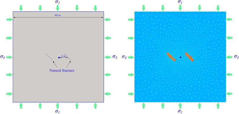
FIGURE 6. Numerical model for case 2. (A) Geometry model; (B) meshing.
Simulation Scheme and Parameter Setting
The stress field loading of case 2 is
Disturbing Stress at the Front of Hydraulic Fractures Induces Natural Fractures to Open and Propagate
The Failure Law of Natural Fractures in the Process of Hydraulic Fractures Approaching
The fracture shape and the distribution of fluid pressure, vertical stress, and shear stress in the process of hydraulic fracture approaching natural fracture are shown in Figure 7. When the injection time is 0.387 s, the peak water pressure in the hydraulic fracture is 8.1 MPa, the propagation length of the hydraulic fracture is 10.32 m, and the distance between the hydraulic fracture tip and the natural fracture is 10.05 m. At this time, the maximum vertical stress acting on the surface of the natural fracture is 14.2953 MPa, and the maximum shear stress is 1.05 MPa, both of which are located at the tip of the natural fracture (Figure 7A).
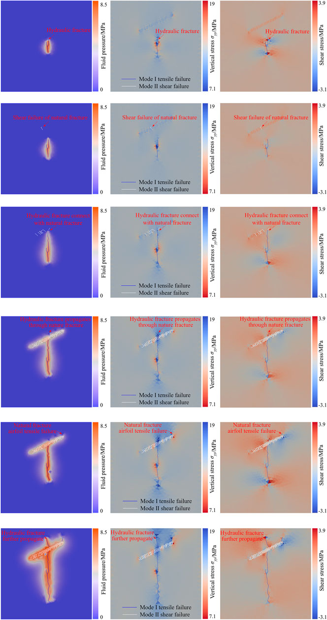
FIGURE 7. The distribution of fluid pressure, vertical stress, and shearing stress during hydraulic fractures propagation. (A) t = 0.387 s; (B) t = 0.430 s; (C) t = 0.882 s; (D) t = 1.462 s; (E) t = 1.634 s; (F) t = 3.354 s.
With the approach of hydraulic fractures, the shear stress acting on the natural fracture surface gradually increases. When the injection time is 0.430 s, the peak water pressure in the hydraulic fracture is 7.3 MPa, the propagation length of the hydraulic fracture is 11.18 m, and the distance between the hydraulic fracture tip and the natural fracture is 8.31 m. At this time, shear failure appears at the natural fracture. The maximum vertical stress acting on the natural fracture surface is 14.2967 MPa, and the maximum shear stress is 1.08 MPa, both of which are located at the shear fracturing (Figure 7B).
When shear failure appears at the natural fracture, the hydraulic fracture tip and frontier water seepage area have not propagated to the natural fractures, which indicates that the shear failure of natural fractures is not induced by water pressure, but the disturbing stress induced by the propagation of hydraulic fractures. That is, the disturbing stress at the front of the hydraulic fracture tip induces shear failure of the natural fracture.
With the hydraulic fracture tip gradually approaching the natural fracture, the shear stress on the natural fracture surface further increases and shear failure continues to occur. When the injection time is 0.882 s, the tip of the hydraulic fracture propagates to the natural fracture and connects with the natural fracture. Shear failure occurred at the junction of natural fractures and hydraulic fractures. At this time, the peak water pressure in the fracture is 7.1 MPa; the maximum vertical stress on the natural fracture surface is 14.50 MPa. The maximum shear stress is 1.74 MPa (Figure 7C).
After the hydraulic fracture is connected with the natural fracture, the water pressure gradually fills the natural fracture, which causes the water pressure acting on the surface of the natural fracture to gradually rise. When the injection time is 1.462 s, the hydraulic fracture propagates through the natural fracture. At this time, the peak water pressure in the fracture is 7.2 MPa, the maximum vertical stress on the natural fracture surface is 16.82 MPa, and the maximum shear stress is 2.73 MPa (Figure 7D).
When the injection time is 1.634 s, the airfoil tension failure occurs in the natural fracture. At this time, the peak water pressure in the fracture is 8.5 MPa, the maximum vertical stress on the natural fracture surface is 18.14 MPa, and the maximum shear stress is 3.60 MPa. After the hydraulic fracture propagates through the natural fracture, as the water pressure in the natural fracture increases, tensile stress concentration tends to occur at the tip of natural fracture. When the tensile stress reaches the tensile strength, the natural fracture will undergo airfoil tension failure (Figure 7E). As the pumping injection continues, hydraulic fracture and airfoil fractures of natural fracture alternately propagate (Figure 7F).
During the hydraulic fractures propagation, the front area of the hydraulic fracture tip is squeezed along the fracture propagation direction, resulting in a compressive stress concentration zone, that is, a disturbing stress area. When there are weak structures such as natural fractures in the propagation direction of hydraulic fractures, the disturbing stress generated by hydraulic fracturing will increase the shear stress of the natural fracture surface. It will induce shear failure of the natural fractures, that is, the fracturing effect induced by disturbing stress of hydraulic fracturing. With the propagation of hydraulic fractures, the disturbing stress on natural fractures gradually increases (Figure 8A). The shear stress also gradually increases (Figure 8B), and the range of shear failure of natural fractures increases accordingly. When the hydraulic fracture propagates to a natural fracture, the hydraulic tension fracture and the disturbed shear fracture will be connected.
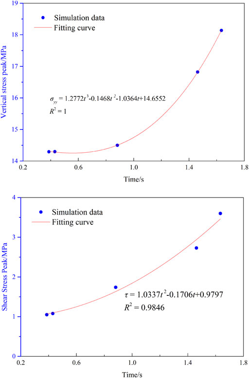
FIGURE 8. The stress peaks of natural fracture during hydraulic fracturing. (A) Vertical stress peak; (B) shear stress peak.
In the process of hydraulic fractures approaching natural fractures, the failure mode of natural fractures includes both shear failure and tensile failure. Because the disturbance range of matrix stress during hydraulic fracturing is larger than the range of water seepage (disturbance range of pore pressure), the shear failure of natural fractures occurs before hydraulic fractures and pressure water seepage area propagates to natural fractures. Therefore, the reason for the shear failure of natural fractures is that the disturbing stress of hydraulic fracturing causes the shear stress acting on the natural fractures to increase. When the hydraulic fractures propagate to natural fractures, the water pressure gradually fills up the natural fractures. With the increase of water pressure in natural fractures, due to the existence of water wedge effect, tensile stress concentration is generated at the tip of natural fracture, which eventually induces the airfoil tensile failure and propagation of natural fracture. Therefore, the tensile failure of natural fractures is caused by the action of fluid pressure. As the natural fractures are filled with water pressure, the failure mode of natural fractures changes from shear failure to tensile failure.
Influencing Factors
The Influence of Principal Stress Difference
The hydraulic fracture propagation process and the distribution of fluid pressure, vertical stress, and shear stress under different principal stress differences are shown in Figure 9. When the principal stress difference is 7.5 MPa, shear failure of the natural fracture appears at t = 0.387 s. When the natural fracture occurs for the first time, the hydraulic fracture has not yet propagated to the natural fracture. At this time, the peak water pressure in the fracture is 7.3 MPa. The propagation length of the hydraulic fracture is 11.18 m. The distance between the hydraulic fracture tip and the natural fracture is 8.31 m. The maximum vertical stress on the natural fracture surface is 14.2967 MPa, and the maximum shear stress is 1.08 MPa, both of which are located at the shear fracturing (Figure 9A). Afterward, with the increase of water pressure in the fracture, the hydraulic fracture first passes through the natural fracture and continues to propagate. Then, airfoil failure occurs at the natural fracture. When airfoil propagation occurs in the natural fracture, the peak water pressure in the fracture is 8.5 MPa. The maximum vertical stress on the natural fracture surface is 18.14 MPa, and the maximum shear stress is 3.60 MPa (Figure 9B).
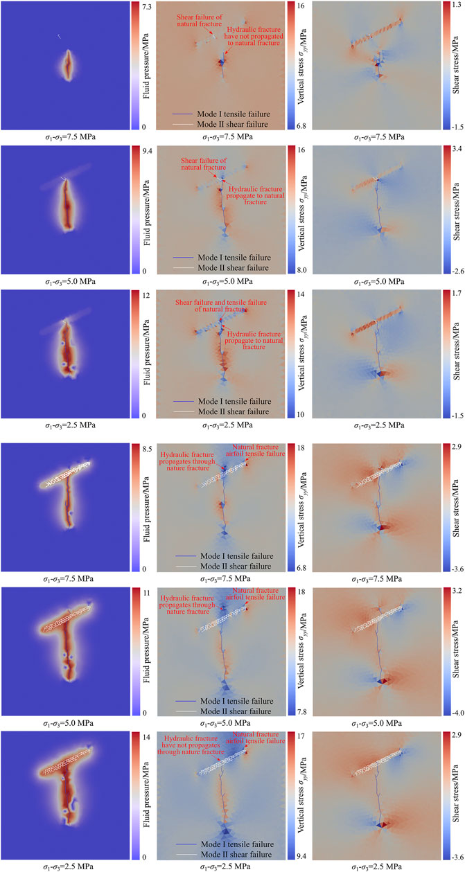
FIGURE 9. The distribution of fluid pressure, vertical stress, and shearing stress during hydraulic fractures propagation under different principal stress differences. (A) First failure of natural fractures; (B) airfoil propagation of natural fractures.
When the principal stress difference is 5.0 MPa, shear failure occurs at the natural fracture after the hydraulic fracture propagates to the natural fracture. At this time, the peak water pressure in the fracture is 9.4 MPa. The maximum vertical stress on the natural fracture surface is 14.32 MPa, and the maximum shear stress is 1.58 MPa (Figure 9A). Since then, as the pumping injection continues, the hydraulic fractures first pass through the natural fractures and continue to propagate, and then airfoil failure occurs at the natural fractures. When the airfoil propagation of the natural fracture occurs, the peak water pressure in the fracture is 11.0 MPa. The maximum vertical stress on the natural fracture surface is 17.97 MPa, and the maximum shear stress is 3.49 MPa (Figure 9B).
When the principal stress difference is 2.5 MPa, both shear and tensile failures occurs at the natural fracture after the hydraulic fracture propagates to the natural fracture. At this time, the peak water pressure in the fracture is 12.0 MPa, the maximum vertical stress on the natural fracture surface is 14.10 MPa, and the maximum shear stress is 1.41 MPa (Figure 9A). When the hydraulic fracture is connected to the natural fracture, due to the high water pressure in the fracture, the tensile stress at the fracture tip is relatively large so that the tensile failure and shear failure occur at natural fracture simultaneously. After that, as the pumping injection continued, airfoil failure occurs at the natural fractures. The hydraulic fractures did not propagate through the natural fractures. When airfoil crack propagates, the peak water pressure in the fracture is 14.0 MPa. The maximum vertical stress on the natural fracture surface is 17.00 MPa, and the maximum shear stress is 2.90 MPa (Figure 9B).
With the increase of the principal stress difference, the range and peak value of the disturbing stress in the front of the hydraulic fracture tip increase (Figure 10A), and the shear stress on the natural fracture surface also increases accordingly (Figure 10B). In the process of hydraulic fractures approaching natural fractures, the more easily the disturbing stress induces shear failure of natural fractures. On the other hand, as the principal stress difference decreases, the water pressure in the fracture rises accordingly. The tensile stress at the tip of the hydraulic fracture becomes larger. When the hydraulic fracture and the natural fracture are connected, natural cracks will also undergo tensile failure while shearing failure occurs. At the same time, the reduction of the principal stress difference leads to an increase in the ability of coal and rock mass to resist tensile failure during the hydraulic fracturing. After the hydraulic fracture propagates to the natural fracture, the ability to pass through the natural fracture is reduced. When the principal stress difference increases to a certain degree, after the hydraulic fracture propagates to the natural fracture, it will not pass through the natural fracture, but will undergo airfoil propagation along the natural fracture.
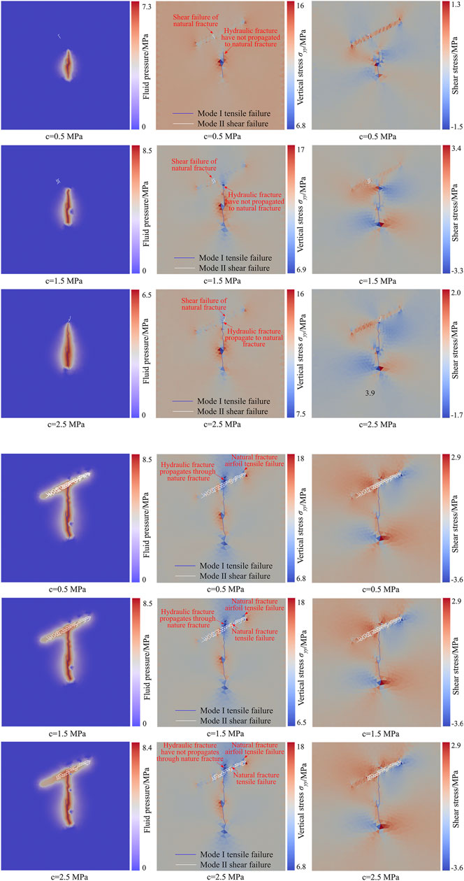
FIGURE 10. The relationship between the vertical stress peak of natural fracture and the difference of principal stress during hydraulic fracturing. (A) Vertical stress peak; (B) shear stress peak.
The Influence of Natural Fracture Cohesion
The hydraulic fracture propagation process and the distribution of fluid pressure, vertical stress, and shear stress under different natural fracture cohesions are shown in Figure 11. When the cohesion of a natural fracture is 1.0 MPa, shear failure of the natural fracture occurs at t = 0.387 s. When the natural fracture occurs for the first time, the hydraulic fracture has not yet propagated to the natural fracture. At this time, the peak water pressure in the fracture is 7.3 MPa. The propagation length of the hydraulic fracture is 11.18 m, and the distance between the hydraulic fracture tip and the natural fracture is 8.31 m. The maximum vertical stress on the natural fracture surface is 14.2967 MPa, and the maximum shear stress is 1.08 MPa, both of which are located at the shear fracturing (Figure 11A). Afterward, with the increase of water pressure in the fracture, the hydraulic fracture first passes through the natural fracture and continues to propagate, and then the airfoil failure occurs at natural fracture. When the airfoil propagation of the natural fracture occurs, the peak water pressure in the fracture is 8.5 MPa. The maximum vertical stress on the natural fracture surface is 18.14 MPa, and the maximum shear stress is 3.60 MPa (Figure 11B).
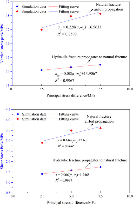
FIGURE 11. The distribution of fluid pressure, vertical stress, and shearing stress during hydraulic fractures propagation under different cohesive of natural fracture. (A) First failure of natural fractures; (B) airfoil propagation of natural fractures.
When the cohesion of the natural fracture is 1.5 MPa, the shear failure of natural fracture occurs at t = 0.667 s. When the natural fracture occurs for the first time, the hydraulic fracture has not yet propagated to the natural fracture. At this time, the peak water pressure in the fracture is 8.5 MPa. The propagation length of hydraulic fracture is 18.72 m, and the distance between the tip of hydraulic fracture and the natural fracture is 3.83 m. The maximum vertical stress on the natural fracture surface is 14.54 MPa, and the maximum shear stress is 1.59 MPa, both of which are located at the shear fracturing (Figure 11A). As the cohesion of natural fractures increases, the ability of natural fractures resisting shear failure increases accordingly. After the hydraulic fracture is connected with the natural fracture, with the increase of the water pressure in the fracture, there will be both shear failure and tension failure in the natural fracture, and shear fracture dominates. After that, the hydraulic fractures first pass through the natural fractures and continue to propagate, and then airfoil failure occurs at natural fracture. When the airfoil propagation of the natural fracture occurs, the peak water pressure in the fracture is 8.5 MPa. The maximum vertical stress on the natural fracture surface is 18.48 MPa, and the maximum shear stress is 3.60 MPa (Figure 11B).
When the cohesion of natural fractures is 2.0 MPa, the shear failure of natural fracture occurs at 0.925 s. When the natural fracture occurs for the first time, the hydraulic fracture has not yet propagated to the natural fracture. At this time, the peak water pressure in the fracture is 6.5 MPa, the maximum vertical stress on the natural fracture surface is 14.48 MPa, and the maximum shear stress is 1.28 MPa (Figure 11A). With the increase of water pressure in natural fractures, the hydraulic fracture propagates through the natural fractures, and then the natural fractures develop airfoil propagation. When airfoil propagation of natural fractures occurs, the peak water pressure in the fracture is 8.4 MPa. The maximum vertical stress on the natural fracture surface is 18.38 MPa, and the maximum shear stress is 3.60 MPa (Figure 11B).
As the cohesion of natural fractures increases, the ability of natural fractures to resist shear failure increases. In the process of hydraulic fractures approaching natural fractures, the less likely it is for disturbing stress to induce shear failure of natural fractures. With the increase of cohesion of natural fractures, when the disturbing stress of hydraulic fracturing induces the initial shear failure of natural fractures, the distance between the hydraulic fracture tip and the natural fracture is smaller (Figure 12). When the hydraulic fracture is connected with the natural fracture, the water pressure enters the natural fracture. Tension failure occurs at the same time as shear failure of natural fractures occurs. Besides, the area of natural fractures where shear failure occurs gradually decreases.
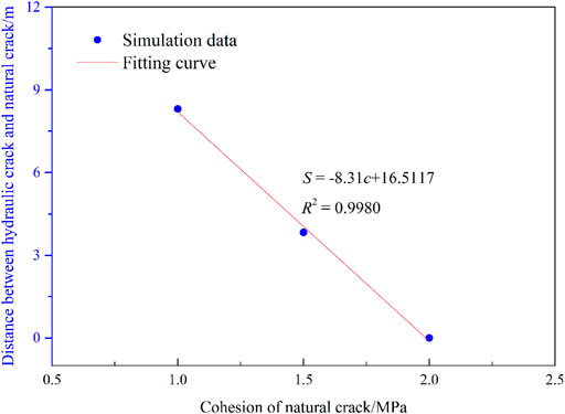
FIGURE 12. The relationship between the distance from the HF tip to NF and the cohesive of NF during the NF initiation.
In addition, the pumping rate, the shear angle of the natural fracture, the approach angle of the hydraulic fracture, and the natural fracture will also affect the process of natural fracture failure induced by the disturbing stress of hydraulic fracturing. Therefore, when hydraulic fracturing is performed in the reservoir with natural fractures developed, whether the natural fractures in front of hydraulic fractures occurs shear failure under the action of the disturbing stress of hydraulic fracturing is mainly determined by the disturbing stress field of the hydraulic fracturing and the shear strength parameters of the natural fracture.
Disturbing Stress on Both Sides of Hydraulic Fracture Induces Shear Failure of Natural Fracture
The failure process of natural fractures on both sides of hydraulic fracture and the distribution of fluid pressure, vertical stress, and shear stress are shown in Figure 13. At the pumping injection time of 0.645 s, the peak water pressure in the fracture is 7.0 MPa, and a compressive stress concentration occurs at the tip of the natural fracture. The peak horizontal stress in the tip area of the natural fracture on the left side of the hydraulic fracture is 8.77 MPa, the peak vertical stress is 25.73 MPa, and the peak shear stress is 5.75 MPa. The peak horizontal stress at the tip of the natural fracture on the right side of the hydraulic fracture is 8.80 MPa, the peak vertical stress is 26.85 MPa, and the peak shear stress is 6.28 MPa. The natural fracture surface is the compressive stress reduction zone (Figure 13A).
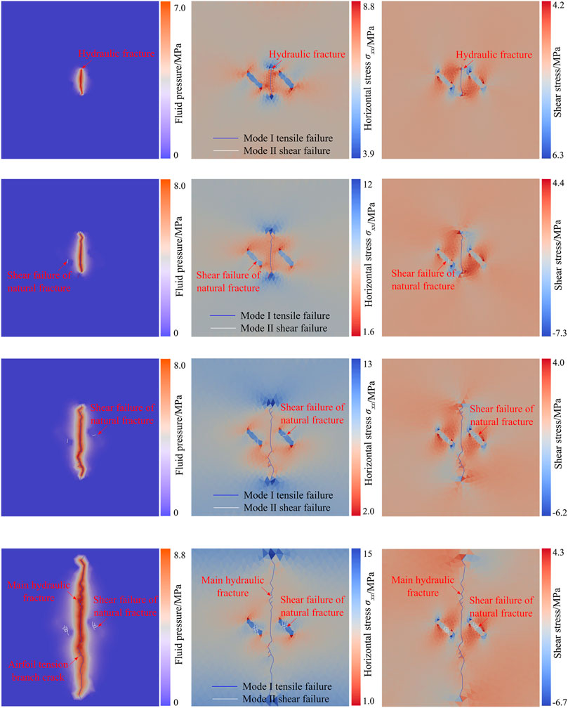
FIGURE 13. The fracturing process of natural fracture and distribution of fluid pressure, horizontal stress, and shearing stress during hydraulic fractures propagation. (A) t = 0.645 s; (B) t = 1.075 s; (C) t = 1.892 s; (D) t = 3.591 s.
With the propagation of hydraulic fractures, the shear stress on the natural fracture surface gradually increases. At the pumping injection time of 1.075 s, shear failure occurs at the natural fracture on the left side of the hydraulic fracture. At this time, the peak water pressure in the fracture is 8.3 MPa, the peak horizontal stress at the tip of the natural fracture on the left side of the hydraulic fracture is 11.94 MPa, the peak vertical stress is 26.70 MPa, and the peak shear stress is 7.26 MPa. The peak horizontal stress at the tip of the natural fracture on the right side of the hydraulic fracture is 12.47 MPa, the peak vertical stress is 27.63 MPa, and the peak shear stress is 6.06 MPa. The shear stress at the shear failure area of the natural fracture on the left is 2.49 MPa (Figure 13B).
With the further propagation of hydraulic fractures, shear failure occurs at the natural fractures on the right side of the hydraulic fractures at the pumping injection time of 1.892 s. At this time, the peak water pressure in the fracture is 8.0 MPa, the peak horizontal stress at the tip of the natural fracture on the left side of the hydraulic fracture is 12.15 MPa, the peak vertical stress is 27.71 MPa, and the peak shear stress is 5.98 MPa. The peak horizontal stress at the tip of the natural fracture on the right side of the hydraulic fracture is 13.34 MPa, the peak vertical stress is 28.64 MPa, and the peak shear stress is 6.22 MPa. The shear stress at the shear failure area of the natural fracture on the right is 2.58 MPa (Figure 13C). After shear failure occurs at the natural fractures on both sides of the hydraulic fracture, as the hydraulic fractures propagate, the shear failure area of the natural fractures on both sides will further expand (Figure 13D).
During the shear failure of natural fractures, the seepage area on both sides of hydraulic fractures did not propagate to the natural fractures. It indicates that the shear failure of natural fractures is induced by the disturbing stress of hydraulic fracturing. During the propagation of hydraulic fractures, there will be compressive stress concentration areas on both sides of the hydraulic fractures, that is, disturbing stress area. When natural fractures exist on both sides of hydraulic fractures, the disturbing stress generated by hydraulic fracturing will increase the shear stress of the natural fracture surface. When the shear stress reaches the shear strength of the natural fracture, the disturbing stress of hydraulic fracturing induces shear failure of the natural fracture.
Conclusion
(1) When natural fractures and other weak structures exist on the front or both sides of hydraulic fracture, the shear stress acting on the surface of natural fracture will increase until the natural fracture failure, which is caused by the disturbing stress of hydraulic fracturing.
(2) The seepage area on the front and both sides of hydraulic fracture did not extend to the natural fracture while the natural fracture failure occurred. It indicates that the shear failure of natural fractures is induced by the disturbing stress of hydraulic fracturing.
(3) When the hydraulic fracture propagates to the natural fracture, the hydraulic tension fracture and disturbed shear fractures are connected and penetrated. As the fluid pressure within the natural fracture surface increases, the hydraulic fracture will continue to propagate through the natural fracture. Meanwhile, due to the action of fluid pressure, a tensile stress concentration will occur at the tip of the natural fracture, which will induce the airfoil tension failure of the natural fracture.
(4) With the increase of the principal stress difference, the range of the disturbing stress area and the peak value of the disturbing stress at the front of the hydraulic fracture tip increase, as well as the shear stress acting on the natural fracture surface. During the process of hydraulic fracture approaching natural fracture, the disturbing stress is easier to induce shear failure of natural fracture.
(5) With the increase of the cohesive force of natural fracture, the ability of natural fractures to resist shear failure increases. As the hydraulic fracture approaches natural fractures, the disturbing stress is more difficult to induce shear failure of natural fracture.
Data Availability Statement
The original contributions presented in the study are included in the article/Supplementary Material; further inquiries can be directed to the corresponding author.
Author Contributions
XZ and BH conceived the research. XZ wrote the manuscript and prepared the figures. BH reviewed and supervised the manuscript. GG involved in the modeling. All authors finally approved the manuscript and thus agreed to be accountable for this work.
Funding
This work was supported by the National Natural Science Foundation of China (No. 52004269) and the Fundamental Research Funds for the Central Universities (No. 2020QN39).
Conflict of Interest
The authors declare that the research was conducted in the absence of any commercial or financial relationships that could be construed as a potential conflict of interest.
Publisher’s Note
All claims expressed in this article are solely those of the authors and do not necessarily represent those of their affiliated organizations, or those of the publisher, the editors, and the reviewers. Any product that may be evaluated in this article, or claim that may be made by its manufacturer, is not guaranteed or endorsed by the publisher.
Acknowledgments
The authors would like to thank the Geomechanics Group at the University of Toronto for their assistance in numerical simulation.
References
Burrows, L. C., Haeri, F., Cvetic, P., Sanguinito, S., Shi, F., Tapriyal, D., et al. (2020). A Literature Review of CO2, Natural Gas, and Water-Based Fluids for Enhanced Oil Recovery in Unconventional Reservoirs. Energy Fuels 34, 5331–5380. doi:10.1021/acs.energyfuels.9b03658
Chen, M., Zhou, J., Jin, Y., and Zhang, G. Q. (2008). Experimental Study on Fracturing Features in Naturally Fractured Reservoir. Acta Petrol. Sin. 29, 431–434. doi:10.7623/syxb200803023
Chen, T., Wang, Z. M., and Yang, G. (2013). Experiments of Fracturing and Pressure Curve Analysis of T-Shape Fractures of Coal Bed. Spec. Oil Gas Reservoirs 20, 123–126. doi:10.3969/j.issn.1006-6535.2013.03.030
Cheng, Y. (2007). “Boundary Element Analysis of the Stress Distribution Around Multiple Fractures: Implications for the Spacing of Perforation Clusters of Hydraulically Fractured Horizontal Wells,” in SPE125769, Charleston, WV, September 2009.
Hu, L., and Ghassemi, A. (2021). Laboratory-Scale Investigation of the Slippage of a Natural Fracture Resulting from an Approaching Hydraulic Fracture. Rock. Mech. Rock. Eng. 54, 2547–2558. doi:10.1007/S00603-021-02398-Y
Huang, B., Wang, Y., and Cao, S. (2015). Cavability Control by Hydraulic Fracturing for Top Coal Caving in Hard Thick Coal Seams. Int. J. Rock Mech. Mining Sci. 74, 45–57. doi:10.1016/j.ijrmms.2014.10.011
Huang, B. X., Chen, S. L., and Cheng, Q. Y. (2016). Basic Problems of Hydraulic Fracturing for Mining and Control Zone Gas in Coal Seams. J. China Coal Soc. 41, 128–137. doi:10.13225/j.cnki.jccs.2015.9024
Huang, B. X., Zhao, X. L., Chen, S. L., and Liu, J. W. (2017). Theory and Technology of Controlling Hard Roof with Hydraulic Fracturing in Underground Mining. Chin. J. Rock Mech. Eng. 36, 1–17. doi:10.13722/j.cnki.jrme.2017.0078
Labuz, J. F., Shah, S. P., and Dowding, C. H. (1985). Experimental Analysis of Crack Propagation in Granite. Int. J. Rock Mech. Mining Sci. Geomech. Abstr. 22, 85–98. doi:10.1016/0148-9062(85)92330-7
Lisjak, A., and Grasselli, G. (2014). A Review of Discrete Modeling Techniques for Fracturing Processes in Discontinuous Rock Masses. J. Rock Mech. Geotechn. Eng. 6, 301–314. doi:10.1016/j.jrmge.2013.12.007
Lisjak, A., Kaifosh, P., He, L., Tatone, B. S. A., Mahabadi, O. K., and Grasselli, G. (2017). A 2D, Fully-Coupled, Hydro-Mechanical, FDEM Formulation for Modelling Fracturing Processes in Discontinuous, Porous Rock Masses. Comput. Geotech. 81, 1–18. doi:10.1016/j.compgeo.2016.07.009
Liu, Q., Sun, L., Liu, P., Chen, L., and Wu, W. (2018). Modeling Simultaneous Multiple Fracturing Using the Combined Finite-Discrete Element Method. Geofluids 2018, 1–20. doi:10.1155/2018/4252904
Liu, Z., Tang, X., Tao, S., Zhang, G., and Chen, M. (2020). Mechanism of Connecting Natural Caves and wells through Hydraulic Fracturing in Fracture-Cavity Reservoirs. Rock. Mech. Rock. Eng. 53, 5511–5530. doi:10.1007/s00603-020-02225-w
Munjiza, A., and Andrews, K. R. F. (1998). NBS Contact Detection Algorithm for Bodies of Similar Size. Int. J. Numer. Meth. Eng. 43, 131–149. doi:10.1002/(SICI)1097-0207(19980915)43:1<131::AID-NME447>3.0.CO;2-S
Munjiza, A., and Andrews, K. R. F. (2000). Penalty Function Method for Combined Finite-Discrete Element Systems Comprising Large Number of Separate Bodies. Int. J. Numer. Meth. Engng. 49, 1377–1396. doi:10.1002/1097-0207(20001220)49:11<1377::AID-NME6>3.0.CO;2-B
Munjiza, A., Andrews, K. R. F., and White, J. K. (1999). Combined Single and Smeared Crack Model in Combined Finite-Discrete Element Analysis. Int. J. Numer. Meth. Engng. 44, 41–57. doi:10.1002/(SICI)1097-0207(19990110)44:1<41::AID-NME487>3.0.CO;2-A
Munjiza, A., and John, N. W. M. (2002). Mesh Size Sensitivity of the Combined FEM/DEM Fracture and Fragmentation Algorithms. Eng. Fracture Mech. 69, 281–295. doi:10.1016/S0013-7944(01)00090-X
Munjiza, A., Owen, D. R. J., and Bicanic, N. (1995). A Combined Finite‐discrete Element Method in Transient Dynamics of Fracturing Solids. Eng. Comput. 12, 145–174. doi:10.1108/02644409510799532
Munjiza, A. (2004). The Combined Finite-Discrete Element Method. Chichester, UK: John Wiley & Sons. doi:10.1002/0470020180
Roegiers, J. C., and Bennaceur, K. (1990). “Stress Relief by Hydraulic Fracturing - Dream or Reality?,” in Proc ISRM International Symposium on Static and Dynamic Considerations in Rock Engineering, Mbabane, Swaziland, September 1990 (Publ Rotterdam: A A Balkema), 257–263.
Yang, J. S., Wang, Y. B., Li, A. Q., Chen, Z. H., Chen, Y. P., and Zou, Y. S. (2012). Experimental Study on Propagation Mechanism of Complex Hydraulic Fracture in Coal-Bed. J. China Coal Soc. 37, 73–77. doi:10.3844/ajassp.2012.1055.1062
Zhang, R., Hou, B., Tan, P., Muhadasi, Y., Fu, W., Dong, X., et al. (2020). Hydraulic Fracture Propagation Behavior and Diversion Characteristic in Shale Formation by Temporary Plugging Fracturing. J. Pet. Sci. Eng. 190, 107063. doi:10.1016/j.petrol.2020.107063
Keywords: hydraulic fracturing, stress disturbance, disturbing stress, natural fracture, tension fracturing, shear fracturing
Citation: Zhao X, Huang B and Grasselli G (2021) Numerical Investigation of the Fracturing Effect Induced by Disturbing Stress of Hydrofracturing. Front. Earth Sci. 9:751626. doi: 10.3389/feart.2021.751626
Received: 01 August 2021; Accepted: 01 September 2021;
Published: 22 September 2021.
Edited by:
Yu Pang, University of Calgary, CanadaCopyright © 2021 Zhao, Huang and Grasselli. This is an open-access article distributed under the terms of the Creative Commons Attribution License (CC BY). The use, distribution or reproduction in other forums is permitted, provided the original author(s) and the copyright owner(s) are credited and that the original publication in this journal is cited, in accordance with accepted academic practice. No use, distribution or reproduction is permitted which does not comply with these terms.
*Correspondence: Bingxiang Huang, aHVhbmdiaW5neGlhbmdAY3VtdC5lZHUuY24=