 Yongshui Kang
 Zhi Geng1,2
 Xuewei Liu
 Xing Huang
- 1State Key Laboratory of Geomechanics and Geotechnical Engineering, Institute of Rock and Soil Mechanics, Chinese Academy of Sciences, Wuhan, China
- 2School of Engineering Sciences, University of Chinese Academy of Sciences, Beijing, China
- 3Jinan Rail Transit Group Co., Ltd., Jinan, China
- 4COMSOL Co., Ltd., Shanghai, China
There is high risk of water inrush and ground collapse accidents when tunnelling in karst areas. Based on the case study of an urban metro tunnel, this paper focuses on karst cave treatment and waterproofing strategies for earth pressure balancing (EPB) shield tunnelling in karst areas containing large amounts of karst caves and fissures. When the shield machine enters the karst area, water gush easily occurs, posing serious threats to tunnelling safety. The distribution characteristic of limestone fractures, karst caves, and fissures in the karst area were analyzed according to the geological survey results. Further, water inrush risk and engineering difficulties were analyzed. Subsequently, a compound karst cave treatment and waterproofing strategy for EPB shield tunnelling was proposed and implemented. Water inflow is successfully reduced and ground collapse accident is avoided using the compound karst cave treatment and waterproofing strategy.
Introduction
Karst is formed through complex chemical and mechanical interactions between groundwater and soluble rock formations such as limestone, dolomite, gypsum, and halite, which can develop into karst caves, karst conduits, and corrosion fissures with a variety of sizes and shapes. Karst aquifers can exhibit an extreme heterogeneity of hydraulic conductivities (Romanova et al., 2003; Li et al., 2016; Liang et al., 2016). Geological disasters such as water inrush and ground collapse occur frequently when tunnelling in karst areas, which pose serious threats to the safety of the tunnel (Wu et al., 2019). Water inrush in karst tunnels usually induces casualties, equipment damage, project delays, and other serious consequences (Yilmaz, 2007; Yang et al., 2016; Li et al., 2019). Moreover, using a shield machine during the tunnelling process, karst caves might cause many geological or engineering hazards such as sink holes, water or stone ingress, damage to segments and the shield machinery, and long-term instability (Cui et al., 2015; Yang et al., 2018; Li et al., 2020). The caves can also cause many difficulties due to pushing side of the “head” of the shield machine, or because of unwanted sinking of it into the hollow (Garašić and Garašić, 2015; Yang et al., 2019; Kovács et al., 2020).
Therefore, special karst cave treatment and waterproofing strategies should be adopted to avoid water inrush and ground collapse accidents when tunneling in karst areas (Li et al., 2013). Advancing geophysical or drilling prospecting is often required to detect the scale, distribution, and water supply of karst caves and fissures before tunnelling. Present geophysical methods mainly include Tunnel Seismic Prediction (TSP) and Ground Penetrating Radar (GPR).
Many researchers have focused on the issues of karst cave treatments during tunnelling processes in recent years. Song et al. (2012) proposed a karst terrain-safe tunnel risk reduction system to cope with the problem of Korean karst in karst areas of the longest railway tunnel in Korea. Alija et al. (2013) studied the excavation and support methods for Gavarres tunnel in Spain’s karst area and investigated measures to efficiently avoid large-scale karst disasters. Cui et al. (2015) discussed potential geohazards during tunnelling in karst caves and verified the effect of the treatment process through a case study. Fan et al. (2018) studied and systematically analyzed the karst characteristics, unfavorable geological disasters, and treatment methods for Yichang-Wanzhou railway tunnel. Wu et al. (2019) studied the required rock thickness to resist water and mud inrush from karst caves under earthquake action and built theoretical solutions for the minimum rock thickness between the tunnel face and the karst cave. Yang et al. (2020) presented a systematic grouting method for a shield tunnel passing through underwater karst regions in water conservation districts. Xu et al. (2021) proposes a typical form of water inrush disaster caused by a combination of steep karst fissures and concealed karst caves and studied its mechanism from aspects of geology and coupled hydro-mechanical interaction.
This research provided valuable information for tunnelling in karst areas. However, geological conditions of karst areas vary in cave characteristic features and hydrogeological conditions; hence, the karst caves treatment and waterproofing measures should be proposed according to the particular geological conditions and safety controlling requirements. Single treatment measures can hardly get satisfactory result when the geological condition is extremely complicated. For instance, common grouting slurry is not applicable for karst fissures with fast-flow water because cement slurry would be washed away by fissure water (Liu et al., 2021). This work focuses on a compound cave treatment and waterproofing strategy for EPB shield tunnelling in karst areas based on an urban metro tunnel in Jinan City of China. A more effective detecting and grouting method would be investigated, and more effective water-proofing measures would be studied according to the geological condition of the karst area.
Jinan is well-known as the City of Springs, and is located in eastern China. The stratum of this city contains numerous karst caves, and the karst water supply is abundant. The karst caves and fissures provide favorable storage conditions and flowing channels for groundwater. The pressure of the confined karst water is high, increasing the risk of water inrush accidents when tunnelling in the karst region. In addition, karst caves might cause serious damage or large displacement to shield machines. Moreover, tunnelling can also cause karst caves to collapse due to excavation disturbance. In order to ensure the safety of tunnel construction, karst caves and fissures should be treated appropriately when tunnelling.
This paper focuses on karst cave treatment and waterproof measures for shield tunnelling in limestone formations based on the case study of R3 Metro Line in Jinan. The engineering geological conditon as well as the characteristic features of karst caves of the limestone formation is analyzed. Subsequently, a compound karst cave treatment and waerproofing measures for shield tunnelling in limestone formation is proposed and implemented in the limestone section.
Engingeering Background
The total length of the first-phase project of Jinan R3 Metro Line is about 21.59 km (as shown in Figure 1). The length of the section between LongAo Station and Olympic Center Station is about 970 m. The buried depth of the tunnel in this section is 13.47–19.66 m, and the maximum slope is 28‰. The inner diameter of the tunnels is 5.8 m, and the thickness of the lining segment is 0.3 m. The tunnel is excavated by earth pressure balancing (EPB) shield machine. The stratum of the section from LongAo station to Olympic Center station is constituted by moderately weathered limestone (Lower Paleozoic Ordovician Majiagou Formation O1m). There are many karst caves and fissures in this section and karst water supply of the section is abundant (as shown in Figure 2 and Figure 3). When the shield machine enters the limestone formation, severe water gushing occurs on the tunnelling surface (Figure 4), which consumes a lot of extra time for drainage and slag cleaning. There is high risk of geological disasters, such as cave roof collapse or water and mud outburst, if no appropriate measures are adopted to treat the karst caves and fissures.
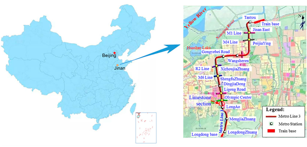
FIGURE 1. Location map of Jinan R3 metro line.
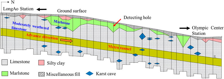
FIGURE 2. Geological profile of detected Karst formation along R3 Line.
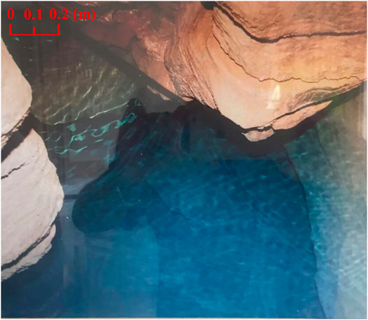
FIGURE 3. A real image of detected karst cave in limestone formation near the tunnel.
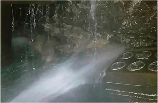
FIGURE 4. Water gushes from the tunnelling face.
Engineering Geological Condition
The limestone of this section is generally moderately weathered. The uniaxial saturated compressive strength of moderately weathered limestone varies from 30 to 80 MPa. The integrity index of the drilling cores is roughly 5–20 (%), and the integrity of the rock mass is classified as an extremely fractured degree. Supplementary geological surveys were carried out in this section before tunnelling. Drilling holes along the tunnel line have detected a large number of karst caves in the moderately weathered limestone. There are approximately 20 karst caves were detected in the section between the LongAo Station and Olympic Center Station. Some of the caves are filled by limestone debris or clays. A diagram of height and counts of detected karst caves are shown in Figure 5. The karst fissures of this section are extremely developed. Typical inner photographs of karst fissures of limestone section using borehole peep method are shown in Figure 6 (Wang et al., 2014).
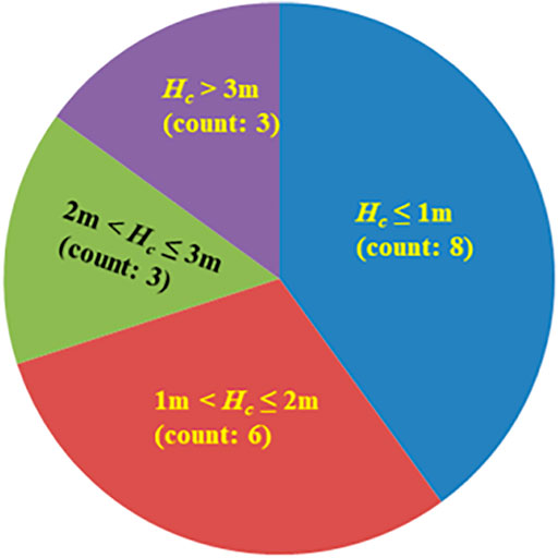
FIGURE 5. Diagram of size and counts of detected karst caves.
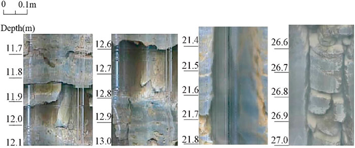
FIGURE 6. Typical inner photograph of karst fissures obtained via the borehole peep method.
This section is in a water-rich region. This aquifer is confined with high pressure. The exposed groundwater in the limestone is mainly fissure karst water with water levels of 11.5–14.7 m. The water supply source is mainly atmospheric precipitation infiltration and replenishment by the river. This aquifer mainly distributes in limestone karst fissures. The fractured fissures and karst caves in the limestone provide water storage conditions and a flowing channel for groundwater.
Engineering Difficulties
The immediate dewatering method is very difficult to conduct due to the abundant fissure water supply. Besides, the stability of adjacent buildings might be threatened by the drawdown of ground water level. Therefore, to ensure safety of the tunnel and adjacent buildings, the water sealing method is more feasible for this section. A compound karst cave treatment and waterproofing strategy should be proposed according to the engineering geological condition. The karst caves near the tunnel should be filled or grouted to avoid collapse accidents. Meanwhile, the seepage channels should be blocked to cut off water inflow at the tunnelling face. The grouting method is commonly used for waterproofing. However, cement slurry can be easily washed away by the fast-flow water in this case. Therefore, special fast-setting slurry should be applied in this section. Moreover, the structure of segments should be improved to adapt to the fractured rock mass and adverse geological condition.
Compound Karst Cave Treatment and Waterproofing Measures
According to the above analysis of geological features and engineering difficulties of the limestone section, a compound karst cave treatment and waterproofing strategy is proposed. The major objective of this compound karst harzards treatment strategy is to improve the geological condition and reduce the water infow during the tunnelling process. The flow chart of karst cave and fissures treatment strategy is shown in Figure 7. Detailed information of the measures is illustrated as follows.
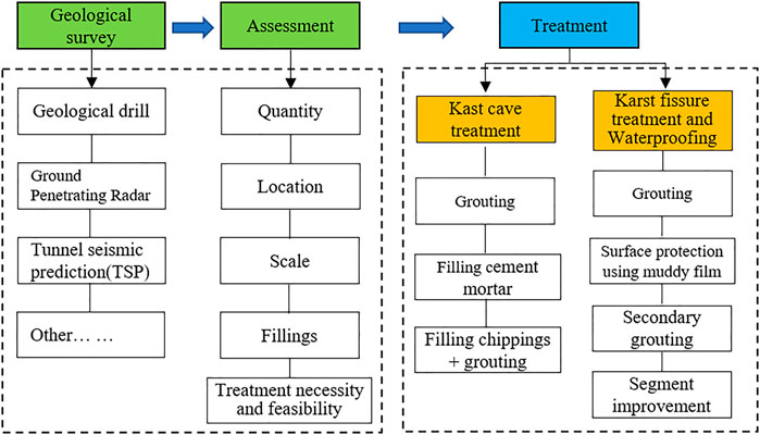
FIGURE 7. Flow chart of karst cave and fissures treatment for karst region along R3 line.
Karst Cave Treatment
As mentioned above, fissures are dense and karst water is abundant in soluble limestone formations. Karst caves of different scales, shapes, and depths are formed by the dissolution and erosion effect of groundwater. It might cause the shield machine to displace, jam, or even cause ground collapse during the tunnelling process. Therefore, to prevent such geo-disasters, all of the caves right above the tunnel and within 5 m from the tunnel contour line should be treated, as shown in Figure 8. Nevertheless, the caves filled with hard plastic clay do not need to be treated.
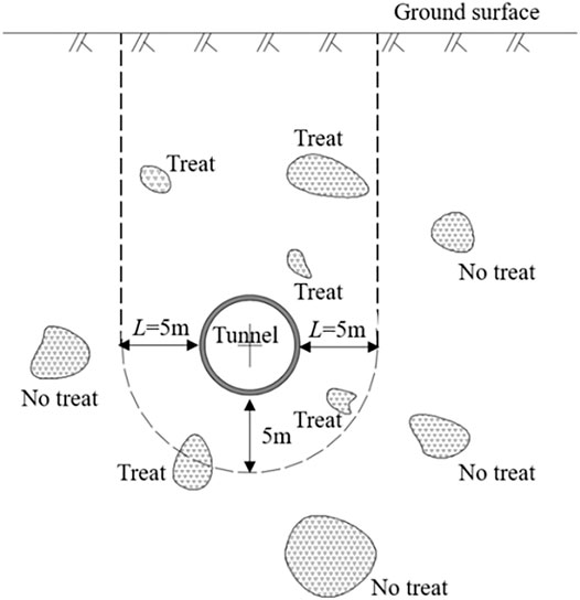
FIGURE 8. The treatment criteria for karst caves around R3 metro Tunnel.
To make clear the specific location, size, and fillings of the karst caves, more supplementary detecting holes would be drilled near karst caves once found. The interval space of the additional holes is set to 2.5 × 2.5 m. The detecting holes can also be used as a grouting hole during the treatment process.
For fully filled caves, concrete cement slurry is used for grouting filling. For unfilled caves and partially -filled caves with heights lower than 1 m, cement slurry (water-cement ratio = 1:1) is used for pressure grouting (0.4–0.8 MPa). For unfilled caves and partially filled caves with heights lower than 2 m, cement mortar is used to fill first and then grouting is used subsequently. For unfilled caves and partially filled caves with heights that exceed 2 m, blowing sand is used first, followed by grouting reinforcement. For super large unfilled caves with heights that exceed 4 m, fill chippings are used first, and then grout (as shown in Table 1). Arrangement of drilling holes and sketch of karst treatment measures are shown in Figure 9.
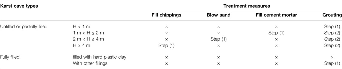
TABLE 1. Treatment measures for different karst cave types.
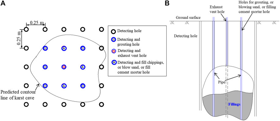
FIGURE 9. (A) Arrangement of drilling holes; (B) profile map.
Grouting holes for karst treatment are reserved on the segments for newly discovered karst caves during the tunnelling process. It can also be used when excessive or abnormal settlement occurs. The water-cement ratio of grouting slurry is set to 1:1, and the grouting pressure is 0.4–0.8 MPa. Sleeve valve pipe and grouting core pipe should be extended to the bottom of the cave. Grouting can be terminated when the suction volume reaches roughly 1–2 L/min and is stabilized for 10 min.
Karst Fissure Treatment and Waterproofing Measures
There are dense karst fissures and caves in the limestone formation. They intersect and connect to each other, forming a huge intricate network for water seepage. When excavating in the moderately weathered limestone, water gushes severely from the tunnelling face due to the confined pressure of karst fissure water. The maximum water inflow exceeds 4.5 m3/h. Meanwhile, the shield tail leaks water. The water flow washes away synchronous grouting slurry. The quality of segment assembly would be affected if the shield tail is not cleaned up, and consequently, the safety and quality of the construction stage would be influenced.
When severe water gushing occurs during the shield tunnelling process, it is necessary to find out the supply source and block the water flowing channel before subsequent tunnelling. Drilling detecting holes is a feasible way to find out the water flowing channel. Based on a comparison of various technical methods, a compound detection and treatment strategy is proposed. Firstly, advancing vertical detecting holes should be drilled on the ground surface to find out the water flowing channel. Secondly, the detecting holes on the water flowing channel should be filled with grout to block the water flow. Consequently, muddy film wall protection technique is applied to seal karst fissures on the tunnel surface. Finally, secondary grouting should be carried out at the shield tail to block water seepage from the shield tail.
As shown in Figure 10, a series of detecting holes, with interval distances of 4 m, are drilled around the tunnelling face. The length of the holes is roughly 23–25 m (5 m beneath the tunnel floor). The drilling sequence is 1→2→3→…→9→10→11 (as shown in Figure 10). Once a water channel is found, concrete slurry is injected into the hole. If the slurry flows out from the tunnelling face, then it can be recognized as the flowing channel of water supply, and the hole should be grouted or poured with mortar. More additional holes can be drilled around this detecting hole and grout through the holes.
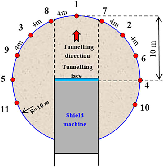
FIGURE 10. Arrangement of detecting drilling holes for the limestone section of R3 Metro Line.
Binary slurry (mixed sodium silicate (Na2OnSiO2) and calcium chloride (CaCl2)) grouting method is adopted to treat water gush problems. The volume ratio of cement paste to sodium silicate is set to C:S = 1: (0.5–1). The concentration of sodium silicate is 35 Baume with the modulus m = 2.4–2.8. The slurry should be replaced with mortar if the binary slurry cannot obtain a satisfactory effect.
Binary slurry injection is conducted by sleeve valve pipes. Slurry can be easily washed away by the fast-flow water and special fast-setting grouting slurry should be applied. Therefore, the initial setting time of slurry is vital for the water sealing effect. It is correlated with the proportion of sodium silicate and calcium chloride. Preparing tests to determine the initial setting time under different proportion condition is necessary. Five initial setting time proportions were allocated for trial, namely 120, 90, 60, 30, and 15s. Each of the slurries with different initial setting times were continuously injected into the hole for 1 h. If the slurry continued to flow out after 1 h, the ratio was replaced with a shorter time until water inflow terminated. A record of the ratio and final pressure value should be made for the follow-up experience data. The slurry should be changed to mortar if the binary slurry cannot seal the water even if the initial setting time has been adjusted to 15s.
Secondary grouting at the shield tail is also implemented. The fissure water might gush from the shield tail when the shield machine moves forward. Therefore, it is necessary to carry out secondary grouting at the shield tail. The secondary grouting slurry is composed of sand (content: 58%), flyash (20%), cement (4%), and water (18%). Grouting pressure should be 2–3 bars higher than the ground water pressure.
Tunnel Surface Protection Technique Using Muddy Film
Balancing shield mud (HDN) is a new kind of auxiliary construction material developed by the Institute of Guangzhou Metro Shield Technology (Zhong et al., 2016). It has excellent workability and adhesion, and it is not easily diluted or washed away by water flow (as shown in Figure 11). An application diagram of balancing shield mud is shown in Figure 12. It has the advantages of stable film formation and good adhesion. Moreover, it is a kind of environmentally friendly protection material.
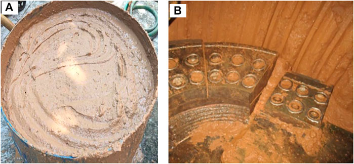
FIGURE 11. (A) Picture of balancing shield mud (HDN); (B) Application effect.
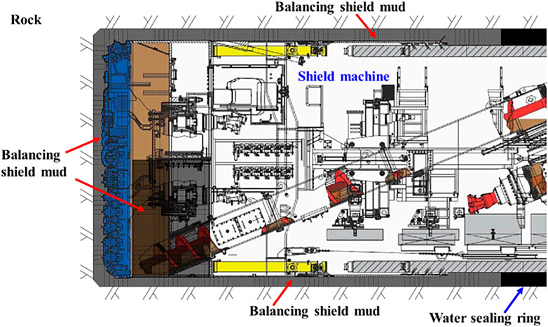
FIGURE 12. Application diagram of balancing shield mud.
Segment Waterproofing
The width of segments used in R3 Line is 1.2 m, and each ring of the segment in the tunnel contains six segments. A set of holes are reserved in segments for subsequent grouting. The maximum water head of the tunnel during the entire operation period is approximately 20.5 m. According to the designing requirements in the waterproof diagram of the segment structure, the elastic gasket can still resist the water pressure of 0.8 MPa when the permissible opening of the segment joint is 6 mm.
However, the shield posture is difficult to control during the tunnelling process due to the influence of karst caves, fissures, and karst water. So, it is difficult to keep the segments connected perfectly. Therefore, flexible caulking is adopted to improve the waterproof ability of the segment. The caulking is sealed by flexible polyurethane sealant (as shown in Figure 13).
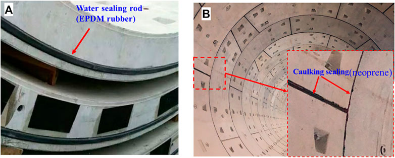
FIGURE 13. (A) Common water sealing rod on the segment; (B) Caulking sealing by flexible polyurethane sealant.
Application Effects
Engineering practice proves that the water gushing on the tunnelling face of R3 line is significantly improved using the compound waterproof and ground reinforcement strategy. The water inflow of the tunnel face is about 4.5 m3/h before treatment, and this value is reduced to 0.3 m3/h after using the treatment measures, and the water inflow on the segments has been sealed completely. Moreover, ground collapse accidents have been succesfuly avoided. The compound treatment measures have effectively reduced the risk of geohazards and provided an reliable environment for the subsequent shield tunnelling.
Conclusion
To avoid water inrush and ground collapse accidents, special cave treatment and waterproofing strategy should be adopted when tunnelling in karst formations. This paper focuses on karst cave treatment and waterproof measures for shield tunnelling in limestone formations based on the case study of R3 metro line in Jinan City.
1) The geological survry result shows that there are plenty of karst caves and fissures in this section and karst water supply of the section is extremely abundant, which can cause great difficulties for the shield tunnelling process and endanger engineering safety.
2) Special karst cave treatment and waterproof measures were proposed including decting holes, filling, and grouting. All of the caves right above the tunnel that within 5 m from the tunnel contour line were treated.
3) The compound karst cave treatment and waterproofing strategy was implemented in R3 line. The water inflow of the tunnel is significantly reduced from 4.5 to 0.25 m3/h after using the compound karst cave treatment measures. Karst water inrush and ground collaspe accidents are sucessfully avoided.
Data Availability Statement
The original contributions presented in the study are included in the article/supplementary material, further inquiries can be directed to the corresponding authors.
Author Contributions
All authors listed have made a substantial, direct, and intellectual contribution to the work, and approved it for publication.
Funding
This research was financially supported by the Natural Science Foundation of China (No. 51774267, 41941018), and the Youth Innovation Promotion Association CAS (No. 2017377), which are highly acknowledged.
Conflict of Interest
Authors LL was employed by Jinan Rail Transit Group Co., Ltd, and LC was employed by COMSOL Co., Ltd.
The remaining authors declare that the research was conducted in the absence of any commercial or financial relationships that could be construed as a potential conflict of interest.
Publisher’s Note
All claims expressed in this article are solely those of the authors and do not necessarily represent those of their affiliated organizations, or those of the publisher, the editors and the reviewers. Any product that may be evaluated in this article, or claim that may be made by its manufacturer, is not guaranteed or endorsed by the publisher.
References
Alija, S., Torrijo, F. J., and Quinta-Ferreira, M. (2013). Geological Engineering Problems Associated with Tunnel Construction in Karst Rock Masses: The Case of Gavarres Tunnel (Spain). Eng. Geology. 157, 103–111. doi:10.1016/j.enggeo.2013.02.010
Cui, Q.-L., Wu, H.-N., Shen, S.-L., Xu, Y.-S., and Ye, G.-L. (2015). Chinese Karst Geology and Measures to Prevent Geohazards during Shield Tunnelling in Karst Region with Caves. Nat. Hazards 77, 129–152. doi:10.1007/s11069-014-1585-6
Garašić, M., and Garašić, D. (2015). Problems with Caves during Tunneling in Dinaric Karst (Croatia). Eng. Geol. Soci. Terri. 5, 497–502. doi:10.1007/978-3-319-09048-1_96
Kovács, J., Újvári, G., Varga, G., Seelos, K., Szabó, P., Dezső, J., et al. (2020). Plio-Pleistocene Dust Traps on Paleokarst Surfaces: A Case Study from the Carpathian Basin. Front. Earth Sci. 8, 189. doi:10.3389/feart.2020.00189
Li, L. P., Tu, W. F., Shi, S. S., Chen, X. G., and Zhang, Y. H. (2016). Mechanism of Water Inrush in Tunnel Construction in Karst Area. Geomat Nat. Hazards Risk 7 (S1), 35–46. doi:10.1080/19475705.2016.1181342
Li, S.-C., Zhou, Z.-Q., Li, L.-P., Xu, Z.-H., Zhang, Q.-Q., and Shi, S.-S. (2013). Risk Assessment of Water Inrush in Karst Tunnels Based on Attribute Synthetic Evaluation System. Tunnelling Underground Space Technol. 38, 50–58. doi:10.1016/j.tust.2013.05.001
Li, S., Gao, C., Zhou, Z., Li, L., Wang, M., Yuan, Y., et al. (2019). Analysis on the Precursor Information of Water Inrush in Karst Tunnels: A True Triaxial Model Test Study. Rock Mech. Rock Eng. 52, 373–384. doi:10.1007/s00603-018-1582-2
Li, X., Ke, T., Wang, Y., Zhou, T., Li, D., Tong, F., et al. (2020). Hydraulic Conductivity Behaviors of Karst Aquifer with Conduit-Fissure Geomaterials. Front. Earth Sci. 8, 30. doi:10.3389/feart.2020.00030
Liang, D.-X., Jiang, Z.-Q., Zhu, S.-Y., Sun, Q., and Qian, Z.-W. (2016). Experimental Research on Water Inrush in Tunnel Construction. Nat. Hazards 81, 467–480. doi:10.1007/s11069-015-2090-2
Liu, X., Hu, C., Liu, Q., and He, J. (2021). Grout Penetration Process Simulation and Grouting Parameters Analysis in Fractured Rock Mass Using Numerical Manifold Method. Eng. Anal. Boundary Elem. 123, 93–106. doi:10.1016/j.enganabound.2020.11.008
Romanov, D., Gabrovšek, F., and Dreybrodt, W. (2003). Dam Sites in Soluble Rocks: a Model of Increasing Leakage by Dissolutional Widening of Fractures beneath a Dam. Eng. Geology. 70, 17–35. doi:10.1016/s0013-7952(03)00073-5
Wang, G., Lu, L., and Zhu, L. (2014). Key and Difficult Points in Geotechnical Engineering Prospecting of Jinan Rail Transit Line R1 Project and the Countermeasures. Urban Rapid Rail Transit. 27 (6), 91–96. doi:10.3969/j.issn.1672-6073.2014.06.022 (in Chinese).
Wu, J., Li, S.-C., Xu, Z.-H., and Zhao, J. (2019). Determination of Required Rock Thickness to Resist Water and Mud Inrush from Karst Caves under Earthquake Action. Tunnelling Underground Space Technol. 85, 43–55. doi:10.1016/j.tust.2018.11.048
Xu, Z., Lin, P., Xing, H., Pan, D., and Huang, X. (2021). Hydro-mechanical Coupling Response Behaviors in Tunnel Subjected to a Water-Filled Karst Cave. Rock Mech. Rock Eng. 54, 3737–3756. doi:10.1007/s00603-021-02423-0
Yang, J., Zhang, C., Fu, J., Wang, S., Ou, X., and Xie, Y. (2020). Pre-Grouting Reinforcement of Underwater Karst Area for Shield Tunneling Passing through Xiangjiang River in Changsha, China. Tunnelling Underground Space Technol. 100, 103380. doi:10.1016/j.tust.2020.103380
Yang, Y., Sun, G., Zheng, H., and Qi, Y. (2019). Investigation of the Sequential Excavation of a Soil-Rock-Mixture Slope Using the Numerical Manifold Method. Eng. Geology. 256, 93–109. doi:10.1016/j.enggeo.2019.05.005
Yang, Y., Tang, X., Zheng, H., Liu, Q., and He, L. (2016). Three-dimensional Fracture Propagation with Numerical Manifold Method. Eng. Anal. Boundary Elem. 72, 65–77. doi:10.1016/j.enganabound.2016.08.008
Yang, Y., Tang, X., Zheng, H., Liu, Q., and Liu, Z. (2018). Hydraulic Fracturing Modeling Using the Enriched Numerical Manifold Method. Appl. Math. Model. 53, 462–486. doi:10.1016/j.apm.2017.09.024
Yilmaz, I. (2007). GIS Based Susceptibility Mapping of Karst Depression in gypsum: a Case Study from Sivas basin (Turkey). Eng. Geol. 90 (1–2), 89–103. doi:10.1016/j.enggeo.2006.12.004
Keywords: karst area, limestone formation, shield tunnelling, karst cave treatment, waterproofing
Citation: Kang Y, Geng Z, Lu L, Chen L, Liu X, Liu B and Huang X (2021) Compound Karst Cave Treatment and Waterproofing Strategy for EPB Shield Tunnelling in Karst Areas: A Case Study. Front. Earth Sci. 9:761573. doi: 10.3389/feart.2021.761573
Received: 20 August 2021; Accepted: 02 September 2021;
Published: 17 September 2021.
Edited by:
Yongtao Yang, Institute of Rock and Soil Mechanics (CAS), ChinaCopyright © 2021 Kang, Geng, Lu, Chen, Liu, Liu and Huang. This is an open-access article distributed under the terms of the Creative Commons Attribution License (CC BY). The use, distribution or reproduction in other forums is permitted, provided the original author(s) and the copyright owner(s) are credited and that the original publication in this journal is cited, in accordance with accepted academic practice. No use, distribution or reproduction is permitted which does not comply with these terms.
*Correspondence: Bin Liu, bGl1YmluQHdocnNtLmFjLmNu; Xing Huang, eGh1YW5nQHdocnNtLmFjLmNu