 Menglai Wang1
 Xiaoshaung Li
 Qihang Li
 Qiusong Chen
- 1Yunnan Phosphate Group Co. Ltd., Kunming, China
- 2School of Civil Engineering, Shaoxing University, Shaoxing, China
- 3Key Laboratory of Rock Mechanics and Geohazards of Zhejiang Province, Shaoxing University, Shaoxing, China
- 4College of Civil Engineering, Qilu Institute of Technology, Jinan, China
- 5School of Resources and Environmental Engineering, Jiangxi University of Science and Technology, Ganzhou, China
- 6School of Resources and Safety Engineering, Central South University, Changsha, China
- 7School of Resources Engineering, Xi’an University of Architecture and Technology, Xi’an, China
In China, mining blasting vibration has seriously threatened the safety and stability of high and steep rock slopes. In this paper, taking the east mining area of Jianshan Phosphorus Mine as the research background, combined with field survey, field blasting test, numerical simulation and theoretical analysis, we systematically studied the adjacent high-steep rock slope and the layered blasting technology of complex ore. Based on wide hole spacing blasting numerical simulation and field tests, the use of 8 × 4 m hole network parameters, oblique line hole-by-hole initiation method, detonator delay using 35 ms between holes, 65 ms between rows and 500 ms within the holes, the rock mass rate was reduced and the drilling workload was decreased. In addition, regression analysis was carried out on a large amount of vibration test data, and the attenuation law and propagation law of blasting vibration of adjacent high and steep slopes were predicted, which provided a reference for mine production blasting. By establishing a mathematical model of cumulative damage of rock mass blasting, it shows that the depth of impact of mining blasting on the slope of Jianshan open-pit was 0–3.6m, but the blasting did not cause overall damage to the adjacent high and steep slopes. In the future, this model can be used to predict rock damage caused by subsequent blasting.
Introduction
In recent years, with the mining of China’s mineral resources, the mineral economy has promoted the rapid development of the social economy. On the contrary, it has caused pollution and damage to the surrounding environment of the mines (Liu et al., 2021). In detail, most of the forms of mining are blasting. Due to the violent vibration caused by explosives during blasting, it will have a serious impact on the surrounding buildings and the lives of residents near the open-pit mine, especially the stability of the high and steep slope near the mine edge, causing the loosening and disintegration of the slope structure of the mine (Sazid. 2017; Umrao et al., 2017). In addition, because of the complexity, instantaneity, uncertainty and differences of blasting media and blasting conditions, the prediction of blasting vibration velocity has always been a major technical problem to be solved urgently (Wang et al., 2019). There are two main reasons for the instability of the high and steep slope of the mine. One is determined by the characteristics of the geological structure of the mine’s high and steep slopes, mainly induced by local hydrogeological conditions. The other is due to changes in the topography of the surrounding high and steep slopes after the mine goes out, such as the instability of the slope caused by the vibration of the impact of blasting. Regardless of the factor, changes in geological structure will cause serious landslides, mudslides under the conditions of blasting vibration and heavy rain, causing immeasurable losses to society (Ramin et al., 2020). Therefore, it is necessary to develop blasting technology and blasting vibration for the open-pit of Jianshan Phosphorus Mine, which can ensure the safety of rock slopes and provide guidance for subsequent mining and blasting.
With the increase in demand for rock mining by blasting in mines, many scholars have carried out in-depth research in theoretical analysis, field tests and numerical simulations (Aldas and Ecevitoglu. 2008; Ren et al., 2014; Wang et al., 2021). Guo et al. analyzed the response of different types of slopes to blasting vibration (Guo et al., 2001). Zhang et al. used the field test method of blasting vibration to carry out an experimental study on the propagation law of blasting vibration under the influence of elevation factors (Zhang et al., 2017). Wang et al. proposed a calculation formula for dynamic time history stability coefficient of bedding high-steep rock slopes driven by underground blasting for the common high-steep bedding rock slopes in engineering (Wang. 2018). Narayan et al. proposed a novel directional controlled blasting technology for unstable highway slopes, which effectively improved the stability of the slope after blasting (Narayan et al., 2020). Wu et al. evaluated the stability of high and steep slopes driven by repeated blasting of the fault zone by combining shaking table tests, limit equilibrium theory, and least squares method (Wu et al., 2020). On the basis of previous research results, Deng and Chen comprehensively discussed the blasting excavation and stability control technology of ultra-high and steep rock slopes in China’s hydropower projects, and discussed its research progress and limitations (Deng and Chen. 2021). On the other hand, Ma et al. studied the weakening of slope stability under the dual effects of rainfall infiltration and blasting vibration (Ma et al., 2021). However, these methods only conduct experiments and theoretical analysis on the stability of the slope after blasting, and have no effective verification and are limited.
In the past 20 years, computer technology has developed rapidly, and numerical simulation has become an important research method (Li et al., 2021; Li et al., 2021). Among them, a series of numerical simulation verification studies have been carried out in the mine blasting process. Xie et al. used SLIDE software to simulate the actual slope model of the open-pit mine, and proposed a slope stability criterion based on the safety factor (Xie et al., 2015). Gui et al. established a numerical simulation considering the geological characteristics of the site by means of the finite difference method, and concluded that the propagation of the explosion wave in the free field is significantly controlled by the geological conditions of the site (Gui et al., 2017). Jiang et al. used the dynamic finite element method to analyze the characteristics of the explosive load, and produced three-dimensional numerical models of open-pit mines and underground mines (Jiang et al., 2018). Chen et al. used the tensile and compression damage model to simulate the entire process of blasting and excavation of a typical bedrock slope, and through parameter analysis, the stability of the slope under the blasting load was ensured (Chen et al., 2019). Li et al. used a comprehensive study method combining theoretical analysis, field testing, and numerical simulation to develop a collaborative blasting technology for high and steep slopes and underground tunnels (Li et al., 2019).
In short, the above methods did not consider the influence of blasting vibration on the stability of adjacent high-steep slopes during the blasting process of open-pit minesand there is no systematic discussion on the mechanical stability and cumulative damage of rock slopes. In the numerical simulation part, most methods use a single finite difference method to simulate and verify the mine blasting process, which has certain limitations. In addition, the propagation and superposition process of the explosion equivalent stress is a major difficulty in studying the mechanical stability of adjacent high-steep slopes under blasting vibration.
Against these challenges, the east mining area of Jianshan Phosphate Mine in Yunnan Province is taken as the research object. Combined with on-site investigation, on-site blasting tests, numerical simulation and theoretical analysis, the open-pit layered blasting technology of complex ore near high and steep slopes was systematically studied. Based on the numerical simulation of wide hole spacing blasting, the method of using 8 × 4 hole network parameters and oblique line hole-by-hole initiation was proposed, which greatly reduced the lump rate of the rock mass and improved the stability of the slope. On the other hand, a detailed analysis of the equivalent stress propagation and equivalent superposition process of blasting vibration was carried out. In addition, the attenuation law and propagation law of blasting vibration on high and steep slopes were predicted, and the cumulative damage model of slope rock mass blasting was established to ensure the safety of adjacent high and steep slopes, thereby promoting the progress of scientific research on blasting in mines.
Engineering Background
Geological Profile
As shown in Figure 1, the Jianshan Phosphate Mine is located near Haikou Town, Xishan District, Kunming City, Yunnan Province, China, with well-developed land and water transportation. The longitude of the study area is 102°06′09″-102°49′56″ and the latitude is 24°08′24″-24°17′35''. In addition, Haikou Town is a heavy industrial zone in Kunming City, with abundant natural resources, convenient transportation and well industrial foundation. The Jianshan Phosphate Mine is located in the middle of the Jianshan mining area.and the northern slope of Jianshan is the exposed part of the bottom rock of the stope. The topography is characterized by alpine topography, with the characteristics of gentle south and steep north. The topography of the foothills is roughly the same as the tilt direction of the rock formations. The peak elevation of the highest peak in the mining area is 2,205.75 m, and the slope has north-south rain fissures and gully cuts, and the lowest erosion base elevation is 1,883.15 m. Over 20 perennial rivers in the surface water system converge into Dianchi Lake, the river at the exit of Dianchi Lake is Haikou River. It flows from east to west through the northern edge of the mining area, the highest water level is 1,886.86 m, and the lowest water level is 1,883.15 m. The annual average rainfall is 886.99 mm and the evaporation is 1,903.8 mm. In addition, there will be frost from December to February, with an average annual frost period of 64–75 days.
FIGURE 1. Location map of Jianshan Phosphate Mine.
Mining Area Structure
The mining area is located in the eastern section of the north wing of the Xiangtiao Village anticline, and the stratum is inclined to the north, in a monoclinic form, with a relatively simple structure and no faults with a drop of more than 30 m. The eastern strata strikes nearly east-west, with steep dips to upright. There are two reverse faults parallel to the axis of the Xiangtiao Village anticline in the southern part of the middle section of the mining area. It pushes the deep strata upwards and makes the ore strata overlap, and the force to the west is weaker than the east. Correspondingly, there are some small axially along strike and inclined wide and gentle fold groups, and vertical fractures with tensile characteristics and small normal faults.
Common folds in the mining area are generally of two types: one is the wide and gentle folds along the inclined direction and strike in the west of the mining area; the other is the traction folds produced by the strong compression in the east of the mining area. The fault structure in the area is not well developed, with only one strike reverse fault group (F1) and one strike normal fault group (F2), which are mainly manifested as duplication or lack of ore layers. In addition, the reverse fault group (F1-1, F1-2) has a certain influence on the northern ore body in the east mining area of Jianshan Phosphorus Mine.
1) F1-1 reverse fault: The F1-1 reverse fault is the main fault in the mining area. The overall strike is close to east-west, with an inclination of 330°–20°, a length of 1,420 m, and the dip angle of the fault plane is steep from the east to the west. The north plate rises, pushing the deep ore layer to the shallower, causing the ore layer to be repeated, and the repeated fault distance is less than 17 m.
2) F1-2 reverse fault: The F1-2 reverse fault is a reverse fault roughly parallel to F1-1. It strikes east-west, with a dip of 340°–360°, a dip angle of 49–60°, and a length of 1,020 m. The north plate rises, the ore layers are repeated, and the vertical fault distance is nearly 30 m.
Blasting Test in Jianshan Stope
Blasting Status and Blasting Plan
Currently, with the continuous decrease of mining depth, the east mining area of Jianshan Phosphorus Mine has formed a high-steep slope with a step height of 30 m, a slope surface of 42–51°, and a slope height of more than 200 m. Since the Jianshan stope is close to the high and steep slopes of Jianshan, and the production operations are more frequent, it is particularly important to avoid the high and steep slopes from being affected by blasting vibration. The production of Jianshan Phosphate Mine adopts the deep-hole step blasting method, and the designed step height is 10 m. The drilling equipment is the Atlas φ152 drilling rig of Jianshan Phosphate Mine and the Atlas φ145 (φ130, φ120, φ115, φ90) drilling rig of the engineering company. Blasting mainly uses 1# rock emulsion explosive and rock expanded ammonium nitrate explosive (the diameter of the roll is 70 mm, 1.5 kg/cylinder).
In this study, the hole mesh parameters used by the mine (5.5 m × 5 m for φ152 drilling rigs, 5 m × 4.5 m for φ145 drilling rigs) are generally acceptable from the field test results. However, when the isosceles triangle is used to arrange the holes and the blast hole density coefficient m = 1.155, the resistance lines of the blast holes in different directions are the most uniform, which is the most effective for increasing the blasting volume of the blast hole and improving the blasting crushing quality (Li et al., 2021; Li et al., 2021). The blasting parameters are designed as follows:
1) Chassis Resistance Line (The horizontal distance from the center of the bottom of the blast hole to the foot of the step):
In the formula: D-Drilling diameter (0.145 m).
2) Super deep:
3) Drilling length:
4) Hole distance:
In the formula: m-Blast hole density factor (1.155).
5) Row spacing:
6) Explosive unit consumption:
7) Explosive charge:
8) Length of explosive charge:
In the formula:
9) Length of blockage:
Based on the empirical formula L2 ≥ (0.7–0.8) Wd ≥ 3.15–3.6m, the designed packing length of 3.6 m is feasible.
As shown in Figure 2, a diagonal hole-by-hole detonation network was used in the field test. Among them, the blasting direction of the blast hole is toward the side of the steps and the steep slope, and the line of the deep holes that are detonated at the same time obliquely intersects the eyebrow line of the steps at an angle (generally 45°) (Geng et al., 2021; Li et al., 2021). The advantage is that the actual distance between the blast holes increases, and the blast hole density coefficient increases, which is beneficial to improve the fragmentation of blasting and reduce the vibration at high and steep slopes. In addition, appropriately increasing the delay interval between holes can increase the frequency of blasting vibration, thereby reducing the impact on adjacent slopes.
FIGURE 2. Slash hole-by-hole detonation network diagram.
Optimization of Blasting Parameters and Field Test
To further improve the blasting effect and increase mine production efficiency we optimized the plan, considering the implementation of a wide hole spacing and small resistance line blasting plan. In order to reduce the on-site test workload, a numerical simulation model was established to provide technical guidance for the optimization plan (Li et al., 2021).
The 1# rock emulsion explosive is used for medium-wave mining and blasting of dolomite and sandy dolomite in Jianshan Phosphate Mine. After investigation, it is found that the reasonable delay time between holes in Jianshan Phosphate Mine is 15–50 ms, and the delay time between rows is 40–80 ms. In addition, combined with the surface delay of the existing plastic detonator network detonator series, it is preliminarily determined that the delay time between the holes is 17 ms/42 ms, 35 ms/65 ms, 25 ms/42 ms, 42 ms/65 ms. In order to better complete geometric solid modeling and dynamic response analysis, ANSYS/LS-DYNA software is used to numerically calculate 16 combinations of wide hole spacing and small resistance line blasting schemes (4 kinds of hole mesh parameters and the delay time between four groups of holes and rows) (Peng. 2005).
Establishment of 3D Numerical Model
The assumptions before the numerical simulation using ANSYS/LS-DYNA are: 1) The rock material is considered an ideal elastoplastic body, and the initial damage such as joints and fissures inside the rock is not considered. 2) The expansion of the detonation product is an adiabatic process, and the seepage effect of the detonation gas is not considered. 3) The shape of the explosive is uniformly distributed in a cylinder, that is, the explosive stress acting on the wall of the blast hole is evenly distributed. 4) The effect of gravity is very small compared to the explosion stress, and the influence of gravity on the charge is not considered.
In the numerical simulation, the 3D solid164 element type is used, and the overall model is established with three times the hole spacing and row spacing (3a × 3b) of the blast hole. There are three blast holes in the model, the blast holes are arranged in a triangle, and the height of the model is 12 m. The free surface from the top to the bottom of the blast hole are respectively: packing material (3.5 m), grain height (7.5 m) and reserved rock bottom (1 m). In addition, the detonation point is set at +2 m, and the model size and blast hole layout are as shown in Figure 3.
FIGURE 3. Model size and blasthole layout drawing.
Numerical Simulation Process
As shown in Figure 4A, the numerical model adopts a meshing method that combines mapping and sweeping to reduce calculation time while ensuring calculation accuracy. In addition, the mesh size near the blasthole is smaller, and the mesh size far away from the blasthole is larger. After the mesh is divided, the number of units in each group of models is between 180 and 220,000. A partial enlarged view of the blasthole grid is shown in Figure 4B. When initiating hole by hole, the front and above the explosion zone are free surfaces. In this order value simulation, the top and front of the model are defined as free surfaces, and the remaining surfaces of the model are set as non-reflective boundary conditions to avoid stress wave reflection at the boundary (Figure 3). Choosing the ALE (Arbitrary Lagrangian Eulerian) algorithm will realize the fluid-solid coupling dynamic analysis to overcome the numerical calculation difficulties caused by the element distortion (Kenamond et al., 2021). In this number value simulation, the total initiation time of each group of calculation models is less than 120 ms. In order to be able to collect the complete element equivalent stress value, the solution time of this simulation is 200 ms, and the calculation step is 1 ms.
FIGURE 4. Blasting model meshing diagram. (A) Wide hole spacing model meshing diagram; (B) Partial enlarged view of blasthole grid.
Numerical Simulation Results
Through the numerical calculation of 16 groups of blasting plans, the propagation process of the equivalent stress between the holes and the superposition of the equivalent stress of each group of plans are analyzed to determine the optimal blasting plan. The model scheme is as shown in Table 1.
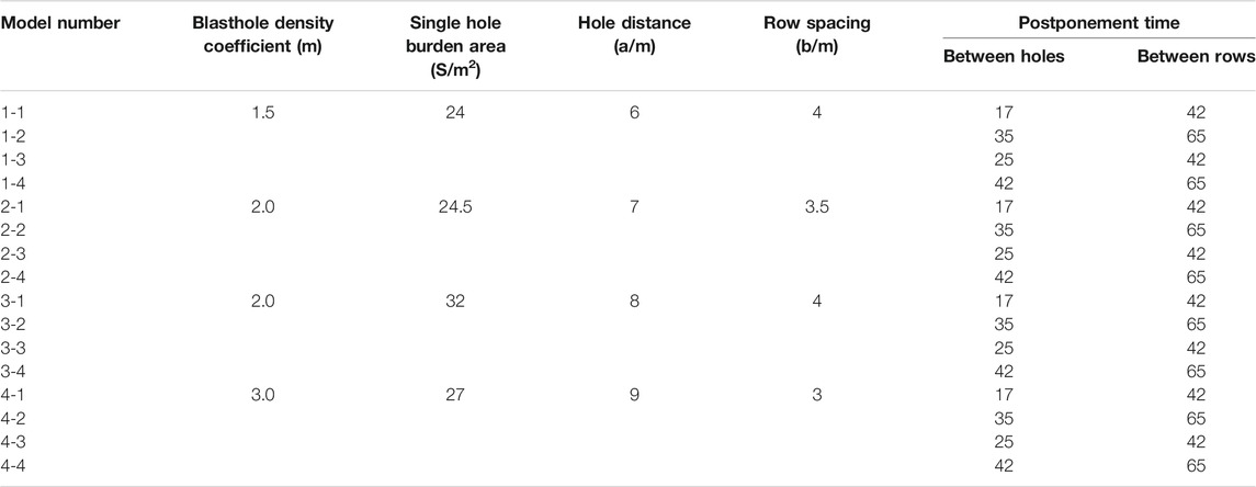
TABLE 1. Numerical simulation scheme.
Analysis of Equivalent Stress Propagation Process
To analyze the rock fragmentation after blasting, here, we take the 1-1 model as the analysis object to illustrate the stress wave propagation process of this group of models at different times.
As shown in Figure 5, the first blasthole detonated at 5 ms and +2 m, and the stress wave propagated outward in a circular shape (Figures 5A,B). The second blasthole detonated at 28 ms, and the equivalent stress of the first and second blastholes was superimposed at the line connecting the center of the blasthole at 28 ms (Figure 5C). At 42 ms, the equivalent stress is reflected from the free surface, forming a reflected tensile wave to break the rock (Figure 5D). The second row of blastholes detonated at 69 ms, and the equivalent stress began to be superimposed between the rows at 69 ms (Figure 5E). At 73 ms, the equivalent stress starts to be superimposed between the holes and between the rows (Figure 5F). At 89–91 ms, the equivalent stress superimposed between holes and rows is obvious. There are stress weakening areas between the center line of the first row of blastholes and the second row of blastholes and between the first row of blastholes and the free surface (Emad et al., 2018; Gao et al., 2021). There is a strong stress concentration phenomenon at the center of the hole (Figures 5G,H). In addition, the stress superposition between rows is more obvious at 150 ms, but the equivalent stress peak value is gradually decreasing (Figure 5I). At 200 ms, the superposition process of equivalent stress between holes and rows gradually stabilizes (Figure 5J).
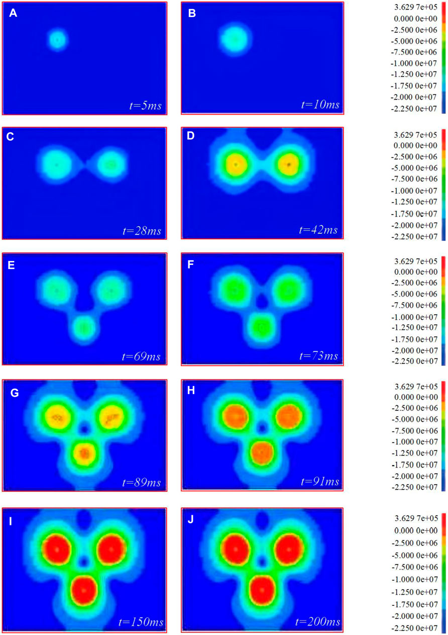
FIGURE 5. The propagation process of stress wave in wide hole spacing blasting. (A–J) are stresses wave propagation effect of t = 5 ms, t = 10 ms, t = 28 ms, t = 42 ms, t = 69 ms, t = 73 ms, t = 89 ms, t = 91 ms, t = 150 ms and t = 200 ms, respectively.
Analysis of Equivalent Stress Superposition
It can be seen from Figures 6–9 that when the hole spacing and row spacing are the same, although the delayed initiation time of each blast hole is different, the superposition of equivalent stress between holes and rows is basically the same. With the increase of hole density coefficient, the superposition of equivalent stress between holes and rows changes greatly. Among them, the stacking between holes is weakened and the stacking between rows is enhanced. In detail, when m = 1.5, the superposition of equivalent stress at the midpoint of blast hole connection is obvious. The equivalent stress first reaches the dynamic tensile strength of rock and causes it to be damaged, and even prone to over broken rock. In addition, the fissures between holes generate a stress wave that diffuses around, resulting in the reduction of the equivalent stress value of the surrounding rocks. A certain range of stress weakening zone is formed between the two rows of blastholes, which inhibits the development of fractures in other directions (Averbeck and Kerscher, 2017). When m = 2, the superposition of equivalent stress between holes and rows is weak. During blasting, it is similar to forming two independent blasting funnels, and it is easy to form large or triangular spine shaped rock ridges between holes. When m = 2.7–3, the superposition of equivalent stress between rows increases. The stress weakening zone moves towards the free surface from the center line of the first row of blastholes to the second row of blastholes, far away from the blasting action range. On the other hand, the fracture angle generated by the small resistance line increases, resulting in the increase of the corresponding free surface and the reflected tensile wave, which is conducive to the fracture of rocks between holes and rows. In summary, during the blasting of dolomite and sandy dolomite in Jianshan phosphate mine, scheme 8 × 4 should be selected to achieve the dynamic tensile strength of rock, ensure rock fragmentation and avoid serious blasting harmful effects.
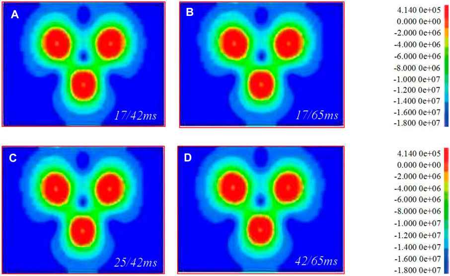
FIGURE 6. 6 × 4 model 200 ms equivalent stress superposition. (A–D) are the superposition of equivalent stresses of 17/42 ms, 17/65 ms, 25/42 ms and 42/65 ms, respectively.
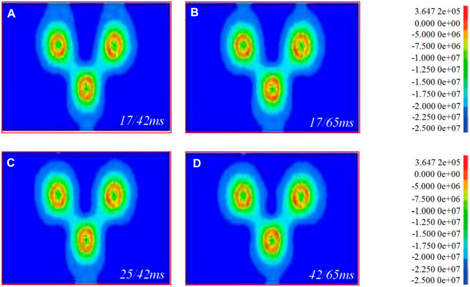
FIGURE 7. 7 × 3.5 model 200 ms equivalent stress superposition. (A–D) are the superposition of equivalent stresses of 17/42 ms, 17/65 ms, 25/42 ms and 42/65 ms, respectively.
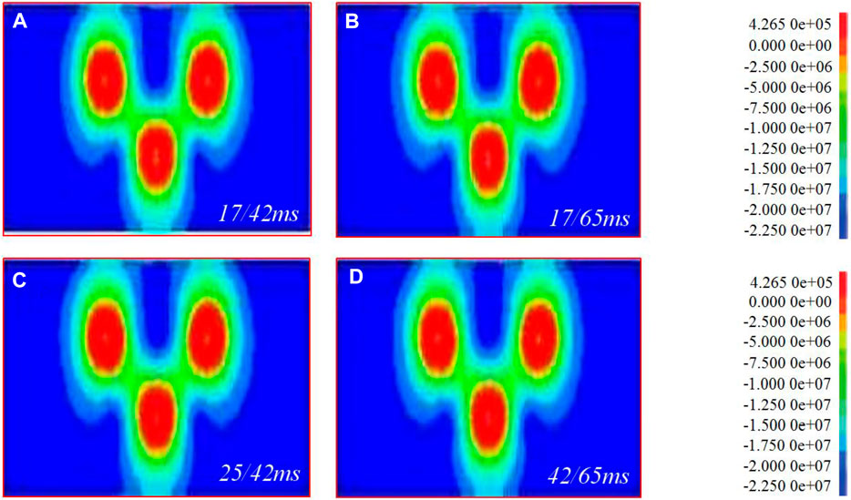
FIGURE 8. 8 × 4 model 200 ms equivalent stress superposition. (A–D) are the superposition of equivalent stresses of 17/42 ms, 17/65 ms, 25/42 ms and 42/65 ms, respectively.
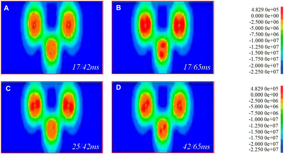
FIGURE 9. 9 × 3 model 200 ms equivalent stress superposition. (A–D) are the superposition of equivalent stresses of 17/42 ms, 17/65 ms, 25/42 ms and 42/65 ms, respectively.
Field Test Results
Based on the optimized combination of blasting parameters, blast hole network parameters, and delay interval, an 8 × 4 scheme is selected for field testand the mine’s existing detonator with a combination of 35 and 65 ms delay interval is used. A diagonal hole-by-hole detonation network is adopted. The blastholes in the same row are connected with the same delay between the holes. When the rows are connected, the second blasthole in the first row is connected to the second row with an interrow delay detonator. A blast hole is connected in the same way for each row in the back row.
Compared with the large block rate of the mine before the test, the large block rate of the three tests using the 8 × 4 scheme has been reduced by 10.4, 16.7, and 15.6% respectively, and the maximum size of the block has been reduced. It shows that with the increase of the blast hole density coefficient, the distance between the rows decreases and the stress superposition between the rows increases, which makes the rock fragmentation more uniform (Miao et al., 2021). In the process of blasting, the influence of flying rocks on the surroundings can be better controlled (Li et al., 2021). After the resumption of mining in the east mining area of Jianshan Phosphorus Mine, by accelerating the slope unloading speed, the slope change rate was effectively slowed down, which provided a guarantee for the continuous mining work below (Li et al., 2021). At the same time, the technology effectively protects the slope surface, makes the entire slope surface smooth and flat, improves production efficiency, and speeds up the slope cutting progress.
Blasting Vibration Monitoring
Blasting Vibration Monitoring of High Slope
As shown in Figure 10A, in order to study the seismic effect of blasting vibration on high slopes and to determine whether the high slopes are within the safe allowable range, we have arranged denser measuring points in areas where the slopes are severely deformed. According to the actual situation of blasting in Jianshan Phosphorus Mine, monitoring points were arranged on the high slope of Jianshan stope (Chen et al., 2020). Figure 10B which shows the time history curve of the vibration velocity of the measuring point at the 2,070 m platform on the east side of the Jianshan slope. During the mining blasting process, more than 20 vibration monitoring tasks were carried out. Among them, several groups of data measured on high slopes are selected for comparison and analysis (Table 2). The comparison results show that: 1) According to the safety allowable vibration speed standard for permanent rock high slopes, the on-site slope vibration speed standard control is determined to be 5 cm/s. However, the peak vibration velocity of the measuring point on the high slope of Jianshan mountain is less than this standard. 2) As shown in Table 2, when the maximum single shot charge is the same, the blasting vibration speed basically decreases with the increase of the blasting center distance. Among them, the elevation amplification effect appeared in 7–12 blasts. This is because the nature of the rock mass, the integrity of the rock mass, the slope and the thickness of the slope and the mountain mass affect the elevation effect. In addition, the slope will affect the intensity and frequency of the blasting vibration wave. Therefore, the degree of elevation magnification effect is different (Chen et al., 2020).
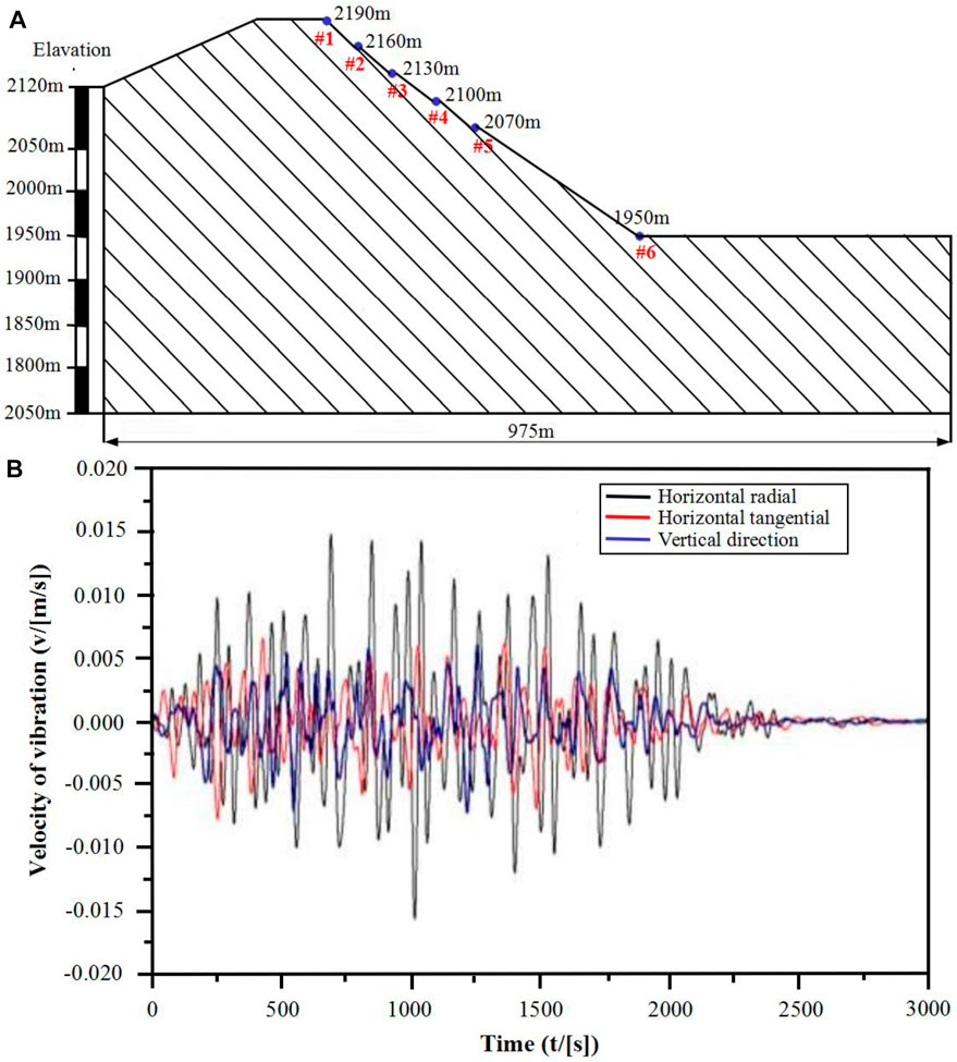
FIGURE 10. Blasting monitoring of high and steep slopes. (A) Layout of high slope monitoring points; (B) Time-history curve of the vibration velocity of the measuring point at the 2070 platform on the east side of the Jianshan slope.
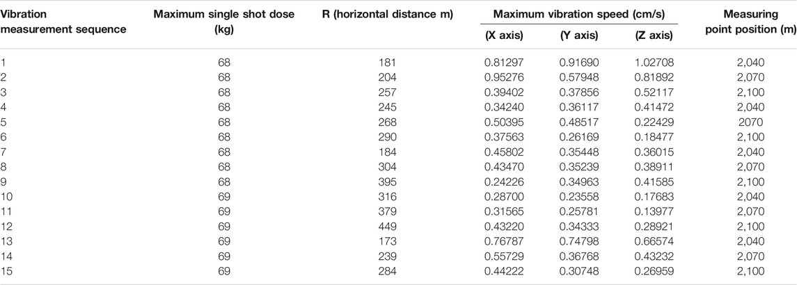
TABLE 2. Typical vibration data statistics table.
Propagation Law of Blasting Vibration on High Slope
Considering the elevation effect of blasting vibration wave propagation, regression analysis is carried out on the measured data in Table 2. The following formula is used to predict the attenuation law and propagation law of blasting vibration on high slopes (Shi et al., 2015):
In the formula: D-Explosion center distance (Horizontal distance, m); Q-Explosive charge; H-Design step height.
The logarithms on both sides of Formula 10 are:
In Formula 11, let
Since Formula 11 can be transformed into a binary linear relationship, use the binary linear regression Matlab program to find the values of k, α, ß.
1) Regression analysis of X-axis vibration data
According to Formula 12, using MATLAB software regression analysis, the result is shown in Figure 11A, the calculation can be: k = 29.7235, a = 1.5243, ß = -0.5152.
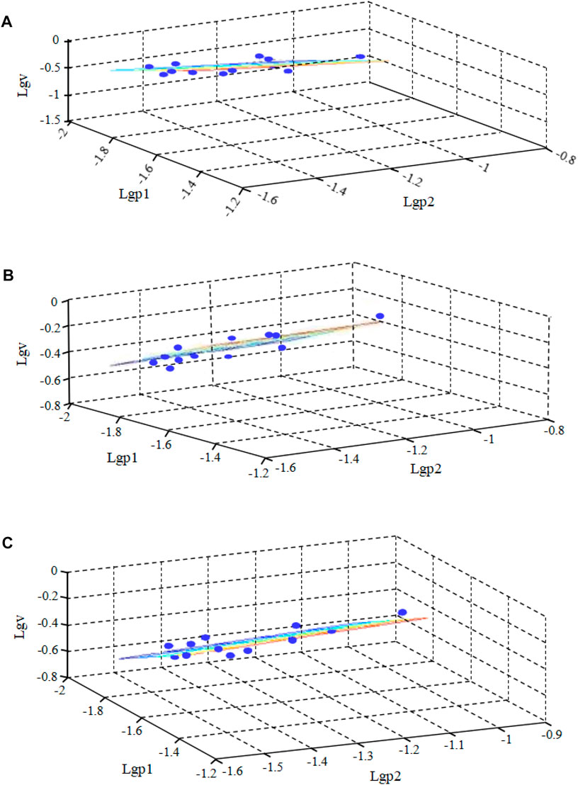
FIGURE 11. Regression analysis results of vibration data of different coordinate axes. (A) X-axis vibration data regression analysis results; (B) Y-axis vibration data regression analysis results; (C) Z-axis vibration data regression analysis results.
Thus, the X-axis propagation law of blasting vibration on the high slope of Jianshan Phosphorus Mine:
Meanwhile, the maximum amount of medicine Qmax for slope safety can be deduced as follows:
2) Regression analysis of Y-axis vibration data
According to Formula 12, the result is shown in Figure 11B, the calculation can be: k = 19.3108, a = 0.8960, ß = 0.0350.
Thus, the Y-axis propagation law of blasting vibration on the high slope of Jianshan Phosphorus Mine:
Meanwhile, the maximum amount of medicine Qmax for slope safety can be deduced as follows:
3) Regression analysis of Z-axis vibration data
According to Formula 12, the result is shown in Figure 11C, the calculation can be: k = 1430.54, a = 1.9255, ß = 0.0701.
Therefore, the Z-axis propagation law of blasting vibration on the high slope of Jianshan Phosphorus Mine:
At the same time, the maximum amount of medicine Qmax for slope safety can be deduced as follows:
Discussions
In order to study the damage of the rock in the slope under the action of blasting vibration, based on the acoustic test of the slope rock mass before and after blasting, the study on the cumulative damage of the slope rock mass under the action of blasting vibration was carried out, and the expansion model of the cumulative damage effect of rock mass blasting was established (Yan. 2007).
Sonic Test and Result Analysis
The sound wave test method before and after blasting is used to judge the quality damage of the slope of Jianshan open-pit mine caused by blasting. Specifically, by testing the post-blast wave velocity Cp2 and the pre-blast wave velocity Cp1 of the rock mass at the same part of the slope of the Jianshan open-pit stope, and calculating the sound wave change rate ΔCp=(1-Cp2/Cp1) of the rock mass at the same part before and after the explosion. If ΔCp is greater than 10%, it is judged that the blasting has destroyed the rock mass. If ΔCp is less than or equal to 10%, it is judged that the blasting is safe and the rock mass is not damaged. In our study, blasting tests were carried out on holes 1#, 2# and 3# respectively, and the wave velocity Cp1 before blasting and the wave velocity Cp2 after blasting of holes 1#-3# were calculated and analyzed. Figures 12A–C are the comparison diagrams of the pre-blast wave velocity Cp1 and post-blast wave velocity Cp2 of the tested holes #1, #2 and #3, respectively.
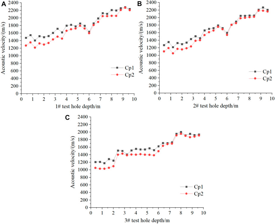
FIGURE 12. Comparison of sonic (longitudinal wave) wave speeds before and after the explosion of different test holes. (A) Comparison of the sonic wave velocity before and after the explosion of the 1# test hole; (B) Comparison of the sonic wave velocity before and after the explosion of the 2# test hole; (C) Comparison of the sonic wave velocity before and after the explosion of the 3# test hole.
As shown in Figure 12, the depth of the impact of blasting on the slope of the Jianshan open-pit is in the range of 0–3.6 m. And according to the sonic test results before and after blasting, the blasting has almost no damage to the deeper rock mass (Xu et al., 2012; Zhang et al., 2020). Thus, the blasting will not cause damage to the adjacent high and steep slopes as a whole.
Establishment of a Cumulative Damage Model for Slope Rock Mass Blasting
The fatigue damage of a material refers to the ratio of the number of active load cycles that the current material can withstand to the number of active load cycles that the material can withstand when it is destroyed (Xu et al., 2021). Generally speaking, the damage to the rock mass caused by blasting excavation will cause the original joint fissures of the rock mass to open, expand, or generate new fissures, resulting in the decrease of the mechanical parameters of the rock mass. The damage degree of rock mass can be expressed as:
In Formula 19, D-damage degree of rock mass; E-the elastic modulus of the rock mass before blasting; E0-the equivalent elastic modulus of the rock mass after blasting; v-sonic wave velocity before rock blasting; v0-sonic wave velocity after rock blasting; K-rock mass integrity factor; η-sonic wave velocity reduction rate.
Rock damage should include two parts: one part is the initial damage D0 caused by geological defects such as natural joints, fissures, and micro-cavities in the rock; the other part is the blasting damage ΔD caused by crack propagation caused by blasting stress waves. Therefore, the rock mass damage D after blasting can be expressed as follows:
Simultaneous Formulas 19, 20 can be obtained:
In Formula 21, vm-sonic velocity of the rock mass; v0-sonic velocity of the rock mass; Δv0-the difference between the sound velocity of the rock mass and the sound velocity of the rock mass; η0-the initial sound velocity reduction rate of the rock mass before blasting.
After the blasting stress wave acts, the rock mass blasting damage appears, and the total damage increases. Based on the change of sound velocity, the damage ΔD of rock mass blasting can be defined as:
In Formula 22, v-sonic wave velocity of rock mass after blasting; Δv-sonic wave velocity of rock mass before and after blasting.
Under the influence of blasting for a long period of time, rock mass blasting damage continues to accumulate. Each blasting damage can be expressed by the sonic velocity reduction rate ΔD, therefore:
The formula for cumulative damage of rock mass under blasting action is:
In Formula 25, D-damage degree of rock mass; n-the number of blasting; A1, A2, A3 and A4-the undetermined constants of the regression curve, respectively.
The cumulative damage expansion model of rock mass blasting characterized by the reference quantity of rock mass sound velocity reduction rate is shown in Formula 24. Under the action of multiple blasting, the damage of the rock mass continues to accumulate. When the accumulation of damage reaches a certain level, it will cause the rock mass instability and destruction. In Figure 13, with the hole depth 2.4 and 4.0 m as the research object of cumulative damage of blasting, a third degree polynomial is used to fit the degree of cumulative damage of rock mass, and the mathematical model of non-linear cumulative damage of rock mass under the action of six blasting is analyzed.
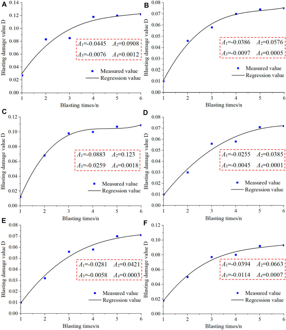
FIGURE 13. Cumulative damage evolution curve. (A) 1# Non-linear cumulative damage evolution curve at 2.4 m of borehole; (B) 1# Non-linear cumulative damage evolution curve at 4.0 m of borehole; (C) 2# Non-linear cumulative damage evolution curve at 2.4 m of borehole; (D) 2# Non-linear cumulative damage evolution curve at 4.0 m of borehole; (E) 3# Non-linear cumulative damage evolution curve at 2.4 m of borehole; (F) 3# Non-linear cumulative damage evolution curve at 4.0 m of borehole.
New Prospects of Research on Mine Blasting Technology
Currently, our method adopts the 8 × 4 m hole network parameters and the slash hole-by-hole initiation method, and the detonator delay time adopts 35 ms between holes, 65 ms between rows, and 500 ms within holes to achieve a better blasting effect. In detail, the blasting fragmentation is relatively uniform, the block rate is reduced, and it will not affect the adjacent high and steep rock slopes. In addition, by establishing a mathematical model of cumulative damage of rock mass blasting, it shows that blasting vibration will not cause damage to the slope as a whole. In the future, we will widely apply this technology in the field of mine blasting. And try to test the blasting methods of 17/42, 25/42, 25/65, 42/65 and other forms of detonators outside the hole with extended time to find a best blasting plan. In addition, since the initial joints and fissures in the rock are not considered in the numerical simulation of blasting in our study, we will consider these factors in the selection of the best blasting plan in future studies. On the other hand, the mathematical model of cumulative damage of rock mass blasting can be used to predict the rock mass damage caused by subsequent blasting, which provides a reference for mine production blasting.
Conclusion
Combined with field survey, field blasting test, numerical simulation and theoretical analysis, this paper systematically studies the open-pit layered blasting technology of a complex mine adjacent to high and steep slope. By monitoring the blasting vibration of high and steep slopes, the attenuation law and propagation law of blasting vibration are predicted. The following conclusions were drawn.
1) Based on the numerical simulation of wide hole spacing blasting and field tests, a scheme using 8 × 4 m hole network parameters, diagonal line-by-hole initiation method, and detonator delay time of 35 ms between holes, 65 ms between rows, and 500 ms within holes is proposed. It reduces the workload of drilling, decreases the cost of drilling, and does not affect the adjacent high and steep slopes.
2) Regression analysis of a large number of blasting vibration test data, obtained the blasting vibration propagation law in the Jianshan stope, and predicted the attenuation law and propagation law of blasting vibration on high and steep slopes, which provided a reference for mine production blasting.
3) A mathematical model for cumulative damage of rock mass blasting is established. The research results show that the impact depth of mining blasting in the Jianshan open-pit on the adjacent high and steep slope is 0–3.6 m, but the blasting has almost no damage to the deeper rock mass, thus, the blasting will not cause damage to the slope as a whole. In the future, this model can be used to predict rock damage caused by subsequent blasting.
Data Availability Statement
The raw data supporting the conclusion of this article will be made available by the authors, without undue reservation.
Author Contributions
MW and QL wrote the original draft and performed the calculation and analysis. XL contributed to the conceptualization, supervision, methodology, and funding acquisition. YH was responsible for the writing of the original draft and funding acquisition. QC and SJ contributed to the conceptualization and obtaining the resources and reviewed and edited the manuscript.
Funding
This work was supported by National Natural Science Foundation of China (No.41867033) and Postdoctoral Science Foundation of China (No. 2019M650144) and State Key Laboratory of Safety and Health for Metal Mines (zdsys 2019-005). The authors wish to acknowledge these supports.
Conflict of Interest
Author MW was employed by the company Yunnan Phosphate Group Co., Ltd.
The remaining authors declare that the research was conducted in the absence of any commercial or financial relationships that could be construed as a potential conflict of interest.
Publisher’s Note
All claims expressed in this article are solely those of the authors and do not necessarily represent those of their affiliated organizations, or those of the publisher, the editors and the reviewers. Any product that may be evaluated in this article, or claim that may be made by its manufacturer, is not guaranteed or endorsed by the publisher.
References
Aldas, G. G. U., and Ecevitoglu, B. (2008). Waveform Analysis in Mitigation of Blast-Induced Vibrations. J. Appl. Geophys. 66 (1), 25–30. doi:10.1016/j.jappgeo.2008.08.004
Averbeck, S., and Kerscher, E. (2017). Critical Plane Analysis of Multiaxial Fatigue Experiments Leading to White Etching Crack Formation. J. Phys. Conf. Ser. 843 (1), 012028–012370. doi:10.1088/1742-6596/843/1/012028
Chen, L., Zhang, W., Gao, X., Wang, L., Li, Z., Böhlke, T., et al. (2020a). Design Charts for Reliability Assessment of Rock Bedding Slopes Stability against Bi-planar Sliding: SRLEM and BPNN Approaches. Georisk: Assess. Manage. Risk Engineered Syst. Geohazards 2020, 1–16. doi:10.1080/17499518.2020.1815215
Chen, L., Zhang, W., Zheng, Y., Gu, D., and Wang, L. (2020b). Stability Analysis and Design Charts for Over-dip Rock Slope against Bi-planar Sliding. Eng. Geology. 275, 105732. doi:10.1016/j.enggeo.2020.105732
Chen, Y., Xu, J., Huo, X., Wang, J., and Younesian, D. (2019). Numerical Simulation of Dynamic Damage and Stability of a Bedding Rock Slope under Blasting Load. Shock and Vibration 2019, 1–13. doi:10.1155/2019/9616859
Deng, K., and Chen, M. (2021). Blasting Excavation and Stability Control Technology for Ultra-high Steep Rock Slope of Hydropower Engineering in China: a Review. Eur. J. Remote Sensing 54 (2), 92–106. doi:10.1080/22797254.2020.1752811
Dokht, R. M. H., Smith, B., Kao, H., Visser, R., and Hutchinson, J. (2020). Reactivation of an Intraplate Fault by Mine‐Blasting Events: Implications to Regional Seismic Hazard in Western Canada. J. Geophys. Res. Solid Earth 125 (6), 1–15. doi:10.1029/2020JB019933
Emad, M. Z., Mitri, H., and Kelly, C. (2018). Dynamic Model Validation Using Blast Vibration Monitoring in Mine Backfill. Int. J. Rock Mech. Mining Sci. 107, 48–54. doi:10.1016/j.ijrmms.2018.04.047
Gao, H., Gao, Y., Wang, J., Fu, Q., Qiao, B., Wei, X., et al. (2021). Study on Bidirectional Blasting Technology for Composite Sandstone Roof in Gob-Side Entry-Retaining Mining Method. Appl. Sci. 11 (7524), 7524. doi:10.3390/app11167524
Geng, J., Li, Q., Li, X., Zhou, T., Liu, Z., and Xie, Y. (2021). Research on the Evolution Characteristics of Rock Mass Response from Open-Pit to Underground Mining. Adv. Mater. Sci. Eng. 2021, 1–15. doi:10.1155/2021/3200906
Gui, Y. L., Zhao, Z. Y., Zhou, H. Y., Goh, A. T. C., and Jayasinghe, L. B. (2017). Numerical Simulation of Rock Blasting Induced Free Field Vibration. Proced. Eng. 191, 451–457. doi:10.1016/j.proeng.2017.05.203
Guo, X. B., Xiao, Z. X., and Zhang, Z. C. (2001). Slope Effect of Blasting Vibration. Chin. J. Rock Mech. Eng. 20 (1), 83–87. doi:10.3321/j.issn:1000-6915.2001.01.019
Jiang, N., Zhou, C., Lu, S., and Zhang, Z. (2018). Effect of Underground Mine Blast Vibrations on Overlaying Open Pit Slopes: A Case Study for Daye Iron Mine in China. Geotech Geol. Eng. 36 (3), 1475–1489. doi:10.1007/s10706-017-0402-x
Kenamond, M., Kuzmin, D., and Shashkov, M. (2021). A Positivity-Preserving and Conservative Intersection-Distribution-Based Remapping Algorithm for Staggered ALE Hydrodynamics on Arbitrary Meshes. J. Comput. Phys. 435, 110254. doi:10.1016/J.JCP.2021.110254
Li, B., Wang, E., Li, Z., Niu, Y., Li, N., and Li, X. (2021a). Discrimination of Different Blasting and Mine Microseismic Waveforms Using FFT, SPWVD and Multifractal Method. Environ. Earth Sci. 80 (1), 1–16. doi:10.1007/S12665-020-09330-7
Li, L., Zhang, J., and Wu, L. (2019). Construction Technology of Cooperative Blasting in High-Steep Slope and Underground Tunnel in Offshore Oil Depot. J. Coastal Res. 98 (sp1), 1–5. doi:10.2112/SI98-001.1
Li, X., Geng, J., Li, Q., Tian, W., and Zhou, T. (2021b). Behaviors and Overlying Strata Failure Law for Underground Filling of a Gently Inclined Medium-Thick Phosphate Deposit. Adv. Civil Eng. 2021, 1–17. doi:10.1155/2021/3275525
Li, X., Liu, Z., and Yang, S. (2021c). Similar Physical Modeling of Roof Stress and Subsidence in Room and Pillar Mining of a Gently Inclined Medium-Thick Phosphate Rock. Adv. Civil Eng. 2021, 1–17. doi:10.1155/2021/6686981
Li, X., Peng, K., Peng, J., and Hou, D. (2021e). Experimental Investigation of Cyclic Wetting-Drying Effect on Mechanical Behavior of a Medium-Grained sandstone. Eng. Geology. 293, 106335. doi:10.1016/j.enggeo.2021.106335
Li, X., Peng, K., Peng, J., and Xu, H. (2021f). Effect of Cyclic Wetting-Drying Treatment on Strength and Failure Behavior of Two Quartz-Rich Sandstones under Direct Shear. Rock Mech. Rock Eng. 54 (7), 1–16. doi:10.1007/s00603-021-02583-z
Li, X. S., Peng, K., Peng, J., and Hou, D. (2021d). Effect of thermal Damage on Mechanical Behavior of a fine-grained sandstone. Arabian J. Geosciences 14 (13), 1–16. doi:10.1007/s12517-021-07607-0
Li, X., Wang, Y., Yang, S., Xiong, J., and Zhao, K. (2021g). Research Progress in the Mining Technology of the Slowly Inclined, Thin to Medium Thick Phosphate Rock Transition from Open-Pit to Underground Mine. Appl. Maths. Nonlinear Sci. 6 (1), 319–334. doi:10.2478/AMNS.2021.2.00017
Li, X., Yang, S., Wang, Y., Nie, W., and Liu, Z. (2021h). Macro-micro Response Characteristics of Surrounding Rock and Overlying Strata towards the Transition from Open-Pit to Underground Mining. Geofluids 2021, 1–18. doi:10.1155/2021/5582218
Liu, B., Tian, K., Huang, B., Zhang, X., Bian, Z., Mao, Z., et al. (2021). Pollution Characteristics and Risk Assessment of Potential Toxic Elements in a Tin-Polymetallic Mine Area Southwest China: Environmental Implications by Multi-Medium Analysis. Bull. Environ. Contam. Toxicol. 2021, 1–11. doi:10.1007/S00128-021-03314-4
Ma, C., Wu, L., Sun, M., and Lei, D. (2021). Failure Mechanism and Stability Analysis of Bank Slope Deformation under the Synergistic Effect of Heavy Rainfall and Blasting Vibration. Geotech Geol. Eng. 2021, 1–14. doi:10.1007/S10706-021-01868-Y
Miao, Y., Zhang, Y., Wu, D., Li, K., Yan, X., and Lin, J. (2021). Rock Fragmentation Size Distribution Prediction and Blasting Parameter Optimization Based on the Muck-Pile Model. Mining, Metall. Exploration 38, 1071–1080. doi:10.1007/S42461-021-00384-0
Narayan, K. B., Arvind, K. M., Singh, M. M., Aditya, R., and Singh, P. K. (2020). Directional Controlled Blasting Technique for Excavation of Unstable Slopes along the Konkan Railway Route. Mining Eng. 72 (7), 106–107.
Peng, D. H. (2005). Analysis of Dynamic Response on Blasting Vibration about Excavated Slope in a Surface Mine. J. China Coal Soc. 30 (6), 705–709. doi:10.3321/j.issn:0253-9993.2005.06.006
Sazid, M. (2017). Effect of Underground Blasting on Surface Slope Stability: A Numerical Approach. Am. J. Mining Metall. 4 (1), 32–36. doi:10.12691/ajmm-4-1-2
Shi, J. J., Xue, L., Zhang, Q., and Meng, H. L. (2015). Vibration Propagation Law in Different Areas of Tunnel Face Caused by Blasting. Amm 744-746, 1005–1009. doi:10.4028/www.scientific.net/AMM.744-746.1005
Umrao, R. K., Singh, R., Sharma, L. K., and Singh, T. N. (2017). Soil Slope Instability along a Strategic Road Corridor in Meghalaya, north-eastern India. Arab J. Geosci. 10 (12), 1–10. doi:10.1007/s12517-017-3043-8
Wang, G. (2018). Stability Analysis of Steep and High Bedding Rock Slopes under the Action of Underground Blasting Vibration. J. China Foreign Highw. 2018 (3), 24–28. doi:10.14048/j.issn.1671-2579.2018.03.006
Wang, J. M., Chen, Z. H., Zhou, Z. H., Zhang, L. F., and Zhang, X. D. (2019). Study on Instability Mechanism of Rock Slope with Trailing Edge Cracks Induced by Blasting and Rainfall. J. Saf. Sci. Technol. 15 (1), 62–68. doi:10.11731/j.issn.1673-193x.2019.01.010
Wang, W., Wei, Y., Guo, M., Li, Y., and Wang, G. D. (2021). Coupling Technology of Deep-Hole Presplitting Blasting and Hydraulic Fracturing Enhance Permeability Technology in Low-Permeability and Gas Outburst Coal Seam: A Case Study in the No. 8 mine of Pingdingshan, China. Adv. Civil Eng. 2021, 1–12. doi:10.1155/2021/5569678
Wu, T., Zhou, C., Jiang, N., Xia, Y., and Zhang, Y. (2020). Stability Analysis for High-Steep Slope Subjected to Repeated Blasting Vibration. Arab J. Geosci. 13 (17), 7207–7227. doi:10.1007/s12517-020-05857-y
Xiang, R., Rong, Z., Qiujing, L., and Xingming, C. (2014). Study on Blasting Safety Technology Applied in Karst Limestone Mine. Proced. Eng. 84, 873–878. doi:10.1016/j.proeng.2014.10.509
Xie, Z. H., Xie, R. Y., and Lu, X. Y. (2015). Stability Analysis on High and Steep Slope of Open-Pit Based on Limit Equilibrium Method. Amm 777, 106–111. doi:10.4028/www.scientific.net/AMM.777.106
Xu, S., Li, Y. H., An, L., and Yang, Y. J. (2012). Study on High and Steep Slope Stability in Condition of Underground Mining Disturbance. J. Mining Saf. Eng. 29 (6), 888–893.
Xu, T., Fu, M., Yang, S.-q., Heap, M. J., and Zhou, G.-l. (2021). A Numerical Meso-Scale Elasto-Plastic Damage Model for Modeling the Deformation and Fracturing of Sandstone under Cyclic Loading. Rock Mech. Rock Eng. 54, 4569–4591. doi:10.1007/S00603-021-02556-2
Yan, C.-b. (2007). Blasting Cumulative Damage Effects of Underground Engineering Rock Mass Based on Sonic Wave Measurement. J. Cent. South. Univ. Technol. 14 (2), 230–235. doi:10.1007/s11771-007-0046-8
Zhang, S., Gao, W., Yan, L., Liu, J., and Liu, L. (2020). The Characteristics of Blasting Vibration Frequency Bands in Jointed Rock Mass Slope. Environ. Earth Sci. 79 (23), 1–16. doi:10.1007/s12665-020-09267-x
Keywords: open-pit mine, high and steep slope, blasting technology, blasting vibration, numerical simulation
Citation: Wang M, Li X, Li Q, Hu Y, Chen Q and Jiang S (2021) Study on Blasting Technology for Open-Pit Layering of Complex Mine Adjacent to High and Steep Slope. Front. Earth Sci. 9:773872. doi: 10.3389/feart.2021.773872
Received: 10 September 2021; Accepted: 04 October 2021;
Published: 16 November 2021.
Edited by:
Yun Zheng, Institute of Rock and Soil Mechanics (CAS), ChinaReviewed by:
Longlong Chen, Politecnico di Milano, ItalyChunyang Zhang, Wuhan University of Technology, China
Copyright © 2021 Wang, Li, Li, Hu, Chen and Jiang. This is an open-access article distributed under the terms of the Creative Commons Attribution License (CC BY). The use, distribution or reproduction in other forums is permitted, provided the original author(s) and the copyright owner(s) are credited and that the original publication in this journal is cited, in accordance with accepted academic practice. No use, distribution or reproduction is permitted which does not comply with these terms.
*Correspondence: Qihang Li, cWloYW5nbGkwMzI1QDEyNi5jb20=; Yunjin Hu, aHV5dW5qaW5AdHNpbmdodWEub3JnLmNu