 Nie Qingke
 Sun Guang1
- 1Hebei Research Institute of Construction and Geotechnical Investigation Co. Ltd., Shijiazhuang, China
- 2School of Materials and Chemistry, University of Shanghai for Science and Technology, Shanghai, China
- 3School of Civil Engineering, Beijing Jiaotong University, Beijing, China
This paper analyzed the earth pressure, pore pressure, and surface settlement of the Luoyang urban rail transit tunnel in a sandy gravel stratum (Henan Province, China) under different burial depths by using field measurement methods. The results showed that the earth pressure as well as pore pressure of the soil layer above the working surface increased sharply and reached their maximum values when the cutter head of the shield gradually crossed the working surface. During the completion of synchronous grouting, the earth pressure and pore pressure increased slightly; when shield tunneling passed through the working surface, the earth pressure is smaller than the original earth pressure due to the unloading effect. The surface settlement curve above the tunnel took on a “V” shape after the completion of the left-side tunnel excavation, conforming to the normal distribution pattern. The surface settlement curve above the two tunnels took on a “W” shape after the completion of the right-side tunnel excavation, which is in good agreement with the proposed theoretical calculations. The findings of this study can help for better understanding the control of safety risk during shield construction.
1 Introduction
To improve increasingly congested road traffic, many cities in China have begun to build subways. In a subway tunnel crossing project, reducing the disturbance to the ground during the construction process is the key to ensuring the safety of the project. The shield construction method is typically used to construct subway tunnels, but the impact of tunnel construction on the surface and underground pipelines and other facilities is still inevitable. The self-stability of sandy gravel strata is poor, so accidents easily occur as shield tunneling is excavated. The important impact of shield tunnel construction on soil disturbance is the settlement caused by front excavation and the filling of shield gaps. At the same time, the stability analysis of the excavation surface and the impact of the shield tail grouting process are also very important. However, there are many difficulties in constructing shield tunnels in sandy gravel strata. It is very important for the safety of surrounding buildings and various facilities to grasp the law of the influence of the entire construction process on soil disturbance (Bai and Li, 2013; Hamrouni et al., 2019; Bai et al., 2021a).
Many scholars have discussed the ground deformation and stability caused by shield tunnel excavation. Peck (1969) assumed that when a tunnel is excavated under undrained conditions, it is possible to use the volume of the tunnel settlement tank to quantify the amount of ground loss, and the surface settlement curve was obtained which presents a normal distribution law. Shahin et al. (2011) accomplished a test study on the surface settlement and earth pressure through a self-developed test device and clarified the impact of the volume loss on the earth pressure by analyzing the test results. Shi et al. (1933) proposed a theory based on the classical Mindlin elastic theory and simulated the ground settlement during a shield tunnel construction process. Attewell and Farmer (1974) thought that the surface settlement of the tunnel center can be approximated as a parabolic function and obtained a formula for calculating the surface settlement. Meguid et al. (2008) summarized the physical models used in soft soil tunnel engineering research and analyzed the advantages of each method. Mair et al. (1985) studied the measured results obtained by tunnel shield excavation and used a centrifugal model to describe the tunnel shield excavation process. Finno and Clough (1985) used the plane strain method to describe tunnel shield excavation, discussed the changes in the ground stress and strain induced by tunnel shield excavation, and discussed the shield machine cutter head. Zhou and Pu (2002) established the interrelation between the support stress and ground settlement and the shape of the ground settlement by centrifugal model tests, which showed that the ground settlement shape conformed to a normal distribution.
Mi and Xiang (2020) suggested a model of tunnel stratum failure considering seepage and compared the experimental results. The calculation results showed that the pore pressure distribution above the working surface was basically symmetrical. Khalid et al. (2020) suggested a mathematical model for predicting the balance performance of earth pressure and verified the rationality of the theoretical model. Tsuno et al. (2020) discussed the mechanical properties of a shield tunnel segment lining through model tests, showing that the axial force of the anchor decreased with an increase in the compression failure. Compared with the cast-in-place reinforced concrete lining, its deformation capacity is larger. The abovementioned studies are all based on clay, silty clay, and sandy clay formations. However, the high content of sandy gravel, large particle size, large friction between particles, small plastic flow, and poor mechanical properties of the gravel stratum seriously affect the construction of shield tunnels. Previous studies on shield tunnel construction in sandy gravel strata have mainly focused on cutter head wear and TBM selection (Bai and Su, 2012; Thewes and Hollmann, 2016; Zumsteg et al., 2016; Bai and Shi, 2017; Bai et al., 2020). The deformation of sandy gravel stratum induced by shield tunnel construction and the stability are less studied (Bai et al., 2014; Khabbazi et al., 2019; Yang and Bai, 2019). In addition, many discussions in recent years have indicated that the temperatures of shield cutter heads are generally 40–50°C under normal working conditions. However, as the mud cake on a shield cutter head increases, the tunneling speed gradually slows down, the torque of the shield cutter head increases significantly, and the cutter head temperature can reach 400–500°C (Bai, 2006; Vinai et al., 2008; Bai et al., 2017; Bai et al., 2019a; Tian et al., 2019). Moreover, the high temperature application of the shield cutter head will increase the temperature increment of the soil layer in contact with the excavation surface (Ren et al., 2001; Bai and Li, 2009; Bai et al., 2016; Chen et al., 2020). Thus, the moisture inside it will migrate under the action of the temperature gradient, forming a water-heat coupling phenomenon in a local area near the excavation surface (Gong et al., 2019; Hu et al., 2020; Qing et al., 2020; Sohaei et al., 2020; Xu et al., 2020; Xue et al., 2020). Many studies have shown that changes in soil temperature and water flow greatly influence the deformation characteristics (Bai et al., 2019b; Yan et al., 2020; Bai et al., 2021b). At present, there is little research on the response of shield tunneling in the transient process. Therefore, it is necessary to discuss the earth pressure, pore pressure, and surface deformation under different burial depths in sandy gravel strata (Flessati and di Prisco, 2018; Zizka et al., 2019; Huang et al., 2020).
Based on the first phase project of Luoyang Urban Rail Transit Line 2 (Henan Province, China), this paper analyzed the measuring results of the earth pressure, pore pressure, and surface settlement at different buried depths in the sandy gravel stratum during the tunnel shielding process. The disturbance effect of shield tunneling on gravel layer includes the factors such as stratum deformation, pore pressure change, stress state characteristics, and the effect of synchronous grouting. A theoretical model is proposed to simulate the ground surface settlement above double-track tunnel. This research can provide a scientific basis for determining the safety of risk control within the scope of shield construction.
2 Measuring Scheme and Results
Three typical sandy gravel stratum sections are selected as the research objects in front of shield tunnel. Earth pressure/pore pressure gauges (precision 0.1 kPa; Figures 1A,B) were used to measure the changes in soil stress and pore pressure (Zhang et al., 2016) at different measuring locations near the tunnel during the tunneling process. A high-precision displacement gauge (precision 0.1 mm; Figure 1C) was used to measure the ground surface settlement during the tunneling process.
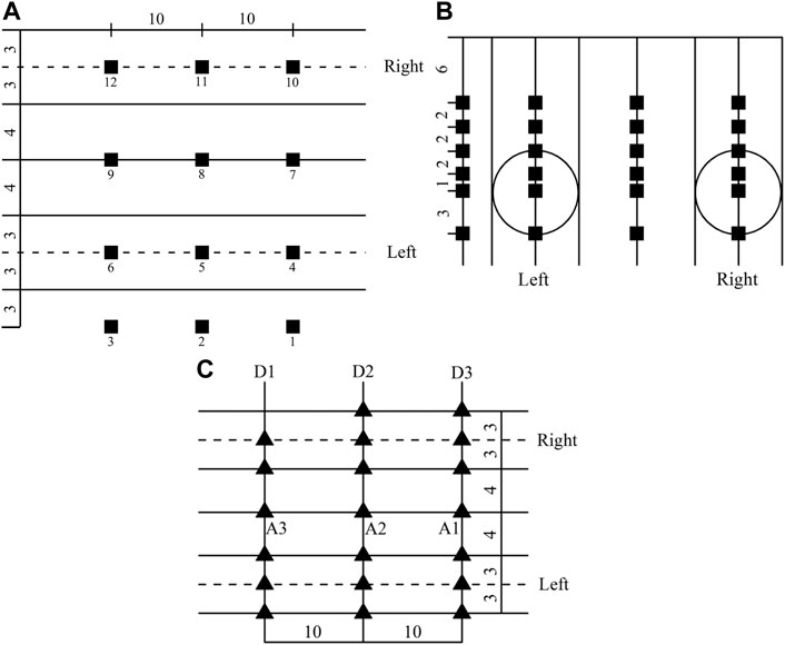
FIGURE 1. Layout of measuring points (unit: m): (A) pore pressure and earth pressure in plane, (B) pore pressure and earth pressure in depth, and (C) soil layer settlement.
2.1 Pore Pressure
Figure 2 indicates the changes in pore pressure at different positions along the tunnel construction direction with the construction time. From the perspective of the construction direction, for the measurement points located on both sides of the tunnel, the shield tunnel is disturbed by the shield construction, resulting in pore pressure (i.e., excess pore water pressure). Figure 2 states clearly that the pore pressures at most of the measurement points do not exceed 2.5 kPa; when the shield construction stops, the pore pressure gradually dissipates over time. In addition, the pore pressure at most measuring points returns to the initial value. The above process is reflected in the measurement points at different depths in the left and right tunneling processes. The pore pressure located at the top of the tunnel changes with the construction time in the same way as the monitoring points at both ends of the tunnel. After being disturbed by shield construction, pore pressure will be formed. At the location of the measuring point, the pore pressure reaches its peak value. For example, the pore pressure of No. 5 was 28 kPa at the burial depth of 16 m (Figure 2C), and the pore pressure of No. 5 was 10.3 kPa at the burial depth of 13 m (Figure 2B).
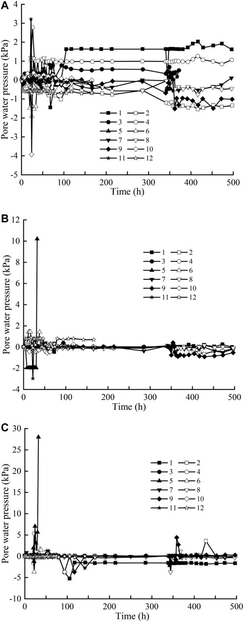
FIGURE 2. Pore pressure with construction time along the direction of tunnel at different burial depths: (A) 10 m, (B) 13 m, and (C) 16 m.
Figure 3 shows the variation in pore pressure along the cross-sectional direction with construction time, which reflects that the pore pressure at the near shield at the same cross-sectional position is significantly greater than that at the far shield, and its influence decreases as the position of the shield machine increases. This is due to the forward thrust squeeze and lateral thrust pressurization when the shield machine is working. For example, as the shield machine gradually enters the monitoring point, the pore pressure of the monitoring point (e.g., near the shield, No. 5) located at a depth of 16 m from the surface at the same section changes significantly, reaching a peak value of 28.0 kPa at 32 h (Figure 3C), while the pore pressure of monitoring point No. 11 at the same depth of 16 m on the surface does not change much (Figure 3C). When the shield machine continues to advance, the pore pressure at each monitoring position will not completely dissipate. This is caused by the existence of grouting pressure. The slurry gradually disappears after reaching a certain strength and finally stabilizes.
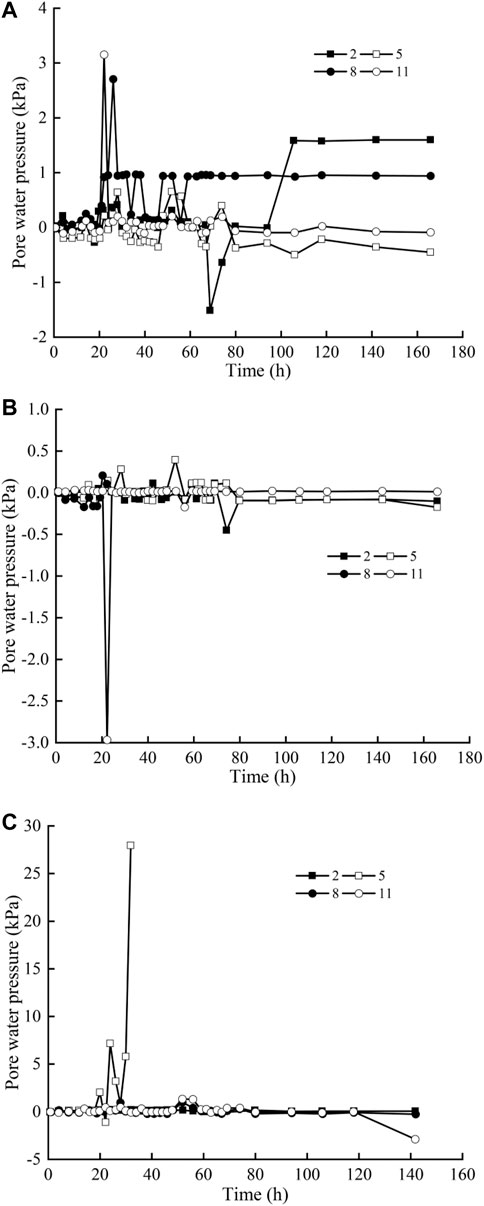
FIGURE 3. Pore pressure with construction time perpendicular to tunnel direction at different burial depths: (A) 10 m, (B) 13 m, and (C) 16 m.
With the decrease in the distance from the shield machine, the pore pressure increases, and the pore pressure monitoring curve appears as a double hump due to the influence of simultaneous grouting and secondary grouting (Zumsteg et al., 2016). When the shield machine pushes past the measuring point, the pore pressure cannot completely dissipate due to the grouting pressure. Then, the pore pressure disappears after the grouting body reaches a certain strength.
2.2 Earth Pressure
Figures 4, 5 show the distribution characteristics of the earth pressure induced by the advancement of the shield at different positions. From the perspective of the construction direction, the earth pressure in front of the tunnel increases due to the shield machine driving forward, and the effect of synchronous grouting construction after the shield machine passes on the earth pressure around the tunnel is also obvious. As a result, the earth pressure above the tunnel significantly increases, and as the shield machine is unloaded by force, the earth pressure decreases significantly and finally stabilizes as the grouting body solidifies. Observing the change in the earth pressure with the construction time, it can be found that the soil layer in front of the tunnel increases due to the compression of the soil during the advancing process of the tunnel. The scope of influence is approximately 6 m in front of the shield machine according to the maximum value obtained from the measurement results.
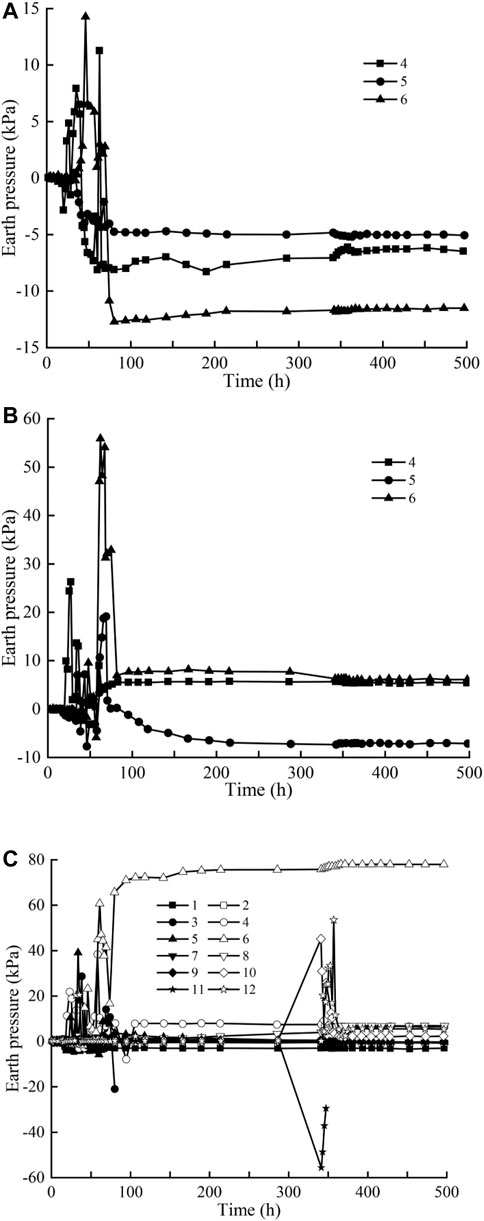
FIGURE 4. Earth pressure with construction time along the direction of tunnel at different burial depths: (A) 6 m, (B) 8 m, and (C) 10 m.
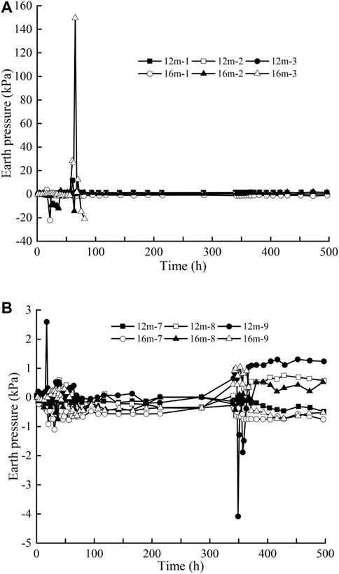
FIGURE 5. Earth pressure on both sides of the tunnel with construction time: (A) left side and (B) right side.
As the shield machine is constructed in the left-side tunnel, its impact on the earth pressure imposed on the left-side tunnel is more obvious. However, when the shield machine is constructed in the right-side tunnel, its impact on the earth pressure is small. The influence of machine advancement on the earth pressure near the shield is significantly greater than that at the far shield, and the influence on pore pressure is similar. For the soil between the two tunnels, due to the impact of shield construction, the earth pressure within 14 m from the ground surface has a different increase in earth pressure. The increase rate increases with the increase of distance from the ground depth. For the soil layer below 14 m away from the ground surface, the stress redistributes due to the soil disturbance of the tunnel shield excavation. Therefore, the earth pressure of the soil below 14 m from the ground surface decreases.
During synchronous grouting, the earth pressures reached their maximum. When synchronous grouting was completed, the earth pressure dropped to a minimum; during the assembly process of the next segment, the earth pressures repeated the abovementioned process of sharp “shoot up-fall back,” but the earth pressure was slightly lesser than the previous process. The earth pressure tends to be stable until the shield machine is far away from the monitoring position (Bai et al., 2020).
2.3 Ground Settlement
Figure 6 displays the settlement during the tunneling of the shield tunnel. In Figure 6, the negative value indicates settlement and the positive value represents uplift. Figure 6 indicates that the excavation of the shield machine not only leads to ground settlement directly above the tunnel but also leads to the settlement of the soil within a certain range on both sides of the tunnel axis. Figure 6A also indicates that the settlement curves at different positions of the shield cutter head distance are roughly similar, and the maximum settlement deformation occurs at the location of the tunnel central axis. When the shield cutter head is 40 m away from the section, the settlement deformation at the central axis of the tunnel reaches a maximum value of 14.5 mm (Figure 6A). The soil within 10 m on each side of the tunnel axis also experienced obvious settlement, and at first, its settlement increased with the distance of the shield machine cutter head away from the set monitoring section and then gradually stabilized.
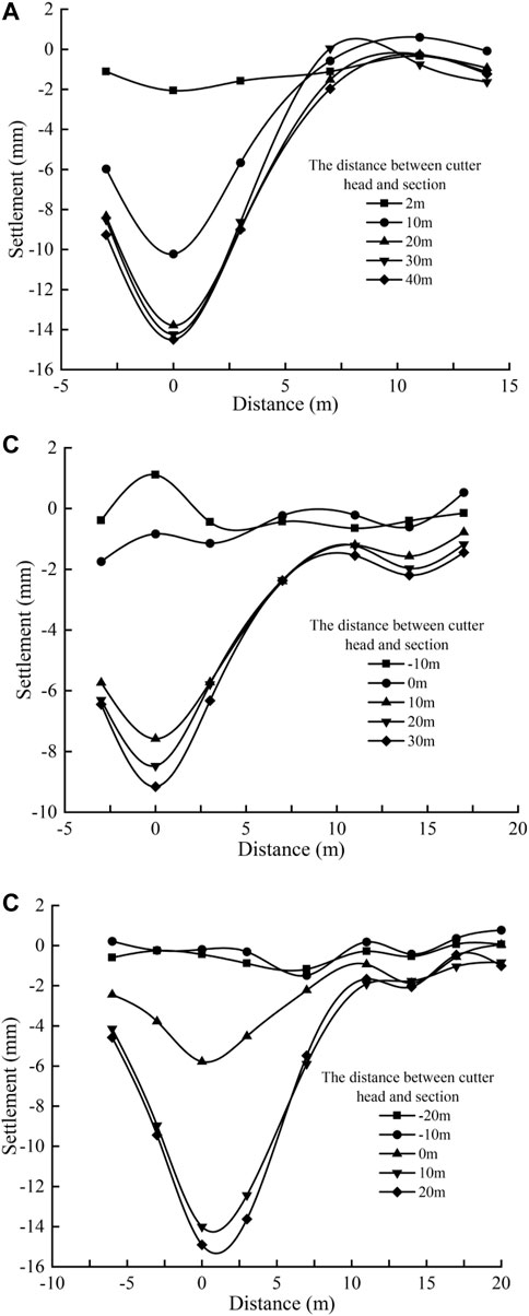
FIGURE 6. Surface settlement curves of the three sections: (A) D1, (B) D2, and (C) D3.
When the shield machine gradually passes through and leaves monitoring section D2, the settlement at the tunnel center is still the most obvious (Figure 6B). As the shield machine gradually approaches the monitoring section, the soil in front of the shield is squeezed and deformed due to the excavation pressure, causing a slight uplift of the surface. When the shield machine traverses the monitoring section, the settlement deformation of the ground surface is small. This is because the soil above the tunnel moves downwards and backwards due to the insufficient support provided by the tunnel excavation, resulting in the previous uplift, and gradually descends and returns to the ground surface with a slight settlement. As the shield machine gradually moved from the measuring section, the soil at the center axis of the tunnel gradually increased due to the settlement that occurred after the shield body broke out, rebounded due to the grouting behind the wall and finally stabilized. Similarly, the soil within 10 m on each side of the tunnel axis also undergoes obvious settlement, and its settlement deformation first increases with the distance of the shield machine cutter head away from the set monitoring section and then gradually stabilizes. Comparing Figure 6B with Figure 6C, it can be found that when the shield machine gradually passes through and drives away from the monitoring section, the soil settles within a certain scope between the tunnel center and the two sides of the tunnel axis. The deformation law is similar to that of the D2 monitoring section. When the shield cutter head distance is −20 m from the monitoring section, the ground surface has a small settlement, and the maximum settlement at the central axis is 0.46 mm; when the shield cutter head distance is −10 m, the soil in front of the shield is subject to excavation. The pressure is squeezed and deformed to the surroundings, causing a slight uplift of the ground surface, which reduces the settlement at the central axis position to 0.2 mm. When the shield cutter head crosses and moves away from the monitoring section, the ground surface above the monitoring section undergoes significant subsidence. When the distance between the disc and the measuring section is 30 m, the surface settlement has stabilized, and the maximum surface settlement at the center of the tunnel is 14.8 mm.
3 Discussion
3.1 Settlement Shape
The characteristics of the D2 and D3 cross-section settlement tanks are analyzed below. The ground surface settlement of the double-side tunnel is presented in Figure 7 after the completion of excavation construction of the right-side tunnel. Figure 7 shows that when the left-side tunnel is excavated, the settlement curve of the ground above the left-side tunnel has a “V” shape. For sections D2 and D3 (the left-side tunnel), the soil surface above the centerline has the largest settlement, at 9.17 and 14.84 mm, respectively. After the completion of the right-side tunnel excavation, the ground settlement curve of the surface above the two-side tunnel is W-shaped. After the excavation of the right tunnel is completed, the maximum ground settlement of the soil surface above the centerline of the left tunnel increases from 9.2 to 9.6 mm. On the other hand, the maximum ground settlement above the centerline of the right tunnel is 12.8 mm. For section D3, the maximum ground settlement above the centerline of the left tunnel increases from 14.8 to 16.7 mm, and the maximum ground settlement above the centerline is 14.0 mm. Figure 7 also shows that the soil on the right side of the left-side tunnel is greatly influenced by the left-side tunnel construction, and different amplitudes of subsidence occur within a certain range of influence. The tunnel excavation has little impact on subsidence, indicating that the construction scope of the right-line tunnel is within the area affected by the construction of the left-side tunnel.
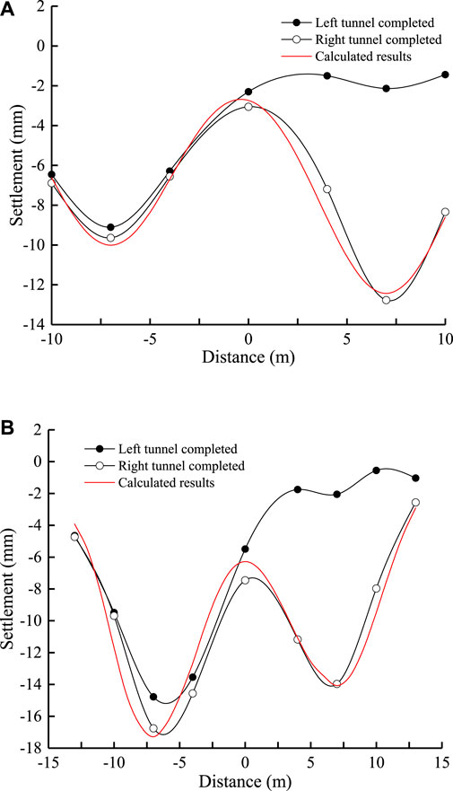
FIGURE 7. Settlement curve perpendicular to tunnel direction at different sections: (A) D2 and (B) D3
A calculation model based on the superposition principle (Suwansawat and Einstein, 2007; Zhou et al., 2021) is proposed to predict the ground settlement of the double-track tunnel, namely,
where x is the transverse horizontal distance from the center line of the double-track tunnel, S(x) is the land subsidence at position x, Smaxf and Smaxl are the maximum ground settlement of the first left-line tunnel and the second right-line tunnel, respectively, L is the distance between the axes of the double-line tunnel, if and il are the width coefficients of cross-section settlement tank for the first left-line tunnel and the second right-line tunnel, respectively, R is the excavation radius of the tunnel, ηf and ηl are the strata volume loss rate of the first left-line tunnel and the second right-line tunnel, respectively.
Figure 7 gives the comparison between the calculated results by using Eq. 1 and the measured results, and the selected calculation parameters are shown in Table 1. The comparison results show that Eq. 1 can well predict the ground surface settlement of the double-track tunnel. Due to the first tunnel construction produces strata disturbance, which affects the later tunnel, the strata volume loss rate of the two tunnels is different, namely,
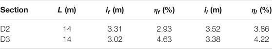
TABLE 1. The selected calculation parameters for the double-track tunnel.
When the settlement in the center of the double-track tunnel (i.e., x = 0) is greater than or equal to
3.2 Variation in Surface Settlement
Figure 8 clearly shows the variation curve of the ground surface settlement with the excavation of the tunnel. When the shield cutter head is digging to the front of the operation, a slight uplift appears on the surface of the soil, and the range of the uplift is 15 m in front of the operation. When the shield machine gradually pulls out and moves away from the working surface, the settlement of the soil above the working surface gradually increases as the distance between the shield machine and the working surface increases. When the distance reaches 20 m, the settlement of the ground surface reaches 9.2 mm, which means that the synchronous grouting effect is poor and cannot fully control the deformation of the stratum. With the effect of the slurry, the soil above the working surface rebounded to a certain extent and finally stabilized.
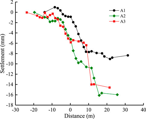
FIGURE 8. Surface settlement along the direction of tunnel at different burial depths.
When the shield cutter head was digging to the front of the operation, the ground surface above the operation surface did not bulge, but a small amount of subsidence occurred (Figure 8B). After the machine is gradually pulled out and away from the working surface, the settlement of the soil above the working surface gradually increases. When the distance between the machine and working surface reaches 15 m, the ground surface settlement reaches a maximum of 16.1 mm. This stage is consistent with the settlement on the left line. It also shows that the effect of synchronous grouting is poor and cannot fully control the deformation of the ground. At the same time, with the effect of grouting behind the wall, the settlement of the soil above the working surface rebounds and finally becomes steady.
When the shield cutter head was digging to approximately 25 m before the operation front, the soil surface above the operation surface had a slight settlement (Figure 8C). When the shield cutter head was digging to the operation front at approximately 15 m, there was slight uplift on the surface above the working surface. The uplift range is approximately 10 m in front of the excavation surface with the advance of construction. When the shield machine gradually exits the working surface, the ground surface above the working surface merges. The synchronous grouting effect is better and has the effect of controlling the deformation of the ground. When the shield machine comes out and gradually moves away from the working surface, the settlement of the surface above the working surface also gradually increases. When the shield machine exited the working surface by approximately 10 m, the ground subsided significantly to 14.0 mm and finally stabilized.
4 Conclusion
As the shield cutter head gradually approached the working surface, the earth pressure and pore pressure above the working surface increased sharply and then reached their maximum values. When the shield tunnel crossed the working surface, due to the unloading of the soil, the earth pressure is smaller than the original earth pressure, gradually.
In the soil layer on both sides of the tunnel, the earth pressure and pore pressure are obviously lower than the soil at the center. The time when the earth pressure and pore pressure reached the peak is later than the time when the shield machine passed the working surface.
With the excavation of the left-side tunnel completed, the ground surface settlement curve above the left-line tunnel took on a “V” shape, which conforms to the normal distribution pattern. As the right-line tunnel was excavated, the surface settlement curve above the two tunnels had a “W” shape, which is in good agreement with the theoretical prediction.
Data Availability Statement
The original contributions presented in the study are included in the article/Supplementary Material, further inquiries can be directed to the corresponding author.
Author Contributions
The main contribution of NQ in this paper is methodology, and the other authors (SG, GS, LH, ZL, and HJ) contributed in investigation and analysis.
Funding
This research was supported by the Hebei Province Postdoctoral Research Projects Merit-Based Funding Program (B2020005008).
Conflict of Interest
Authors NQ, SG, LH, and ZL are employed by Hebei Research Institute of Construction and Geotechnical Investigation Co. Ltd.
The remaining authors declare that the research was conducted in the absence of any commercial or financial relationships that could be construed as a potential conflict of interest.
Publisher’s Note
All claims expressed in this article are solely those of the authors and do not necessarily represent those of their affiliated organizations, or those of the publisher, the editors, and the reviewers. Any product that may be evaluated in this article, or claim that may be made by its manufacturer, is not guaranteed or endorsed by the publisher.
References
Attewell, P. B., and Farmer, I. W. (1974). Ground Deformations Resulting from Shield Tunnelling in london clay. Can. Geotech. J. 11 (3), 380–395. doi:10.1139/t74-039
Bai, B. (2006). Fluctuation Responses of Saturated Porous media Subjected to Cyclic thermal Loading. Comput. Geotechnics 33 (8), 396–403. doi:10.1016/j.compgeo.2006.08.005
Bai, B., Guo, L., and Han, S. (2014). Pore Pressure and Consolidation of Saturated Silty clay Induced by Progressively Heating/cooling. Mech. Mater. 75, 84–94. doi:10.1016/j.mechmat.2014.04.005
Bai, B., Jiang, S., Liu, L., Li, X., and Wu, H. (2021). The Transport of Silica Powders and lead Ions under Unsteady Flow and Variable Injection Concentrations. Powder Technol. 387, 22–30. doi:10.1016/j.powtec.2021.04.014
Bai, B., and Li, T. (2013). Irreversible Consolidation Problem of a Saturated Porothermoelastic Spherical Body with a Spherical Cavity. Appl. Math. Model. 37 (4), 1973–1982. doi:10.1016/j.apm.2012.05.003
Bai, B., and Li, T. (2009). Solutions for Cylindrical Cavity in Saturated Thermoporoelastic Medium. Acta Mechanica Solida Sinica 22 (1), 85–94. doi:10.1016/s0894-9166(09)60093-8
Bai, B., Rao, D., Chang, T., and Guo, Z. (2019). A Nonlinear Attachment-Detachment Model with Adsorption Hysteresis for Suspension-Colloidal Transport in Porous media. J. Hydrol. 578, 124080. doi:10.1016/j.jhydrol.2019.124080
Bai, B., and Shi, X. (2017). Experimental Study on the Consolidation of Saturated Silty clay Subjected to Cyclic thermal Loading. Geomech. Eng. 12 (4), 707–721. doi:10.12989/gae.2017.12.4.707
Bai, B., and Su, Z. (2012). Thermal Responses of Saturated Silty clay during Repeated Heating-Cooling Processes. Transp Porous Med. 93 (1), 1–11. doi:10.1007/s11242-012-9939-6
Bai, B., Wang, J., Zhai, Z., and Xu, T. (2017). The Penetration Processes of Red Mud Filtrate in a Porous Medium by Seepage. Transp Porous Med. 117 (2), 207–227. doi:10.1007/s11242-017-0829-9
Bai, B., Xu, T., and Guo, Z. (2016). An Experimental and Theoretical Study of the Seepage Migration of Suspended Particles with Different Sizes. Hydrogeol J. 24 (8), 2063–2078. doi:10.1007/s10040-016-1450-7
Bai, B., Yang, G.-c., Li, T., and Yang, G.-S. (2019). A Thermodynamic Constitutive Model with Temperature Effect Based on Particle Rearrangement for Geomaterials. Mech. Mater. 139, 103180. doi:10.1016/j.mechmat.2019.103180
Bai, B., Zhang, J., Liu, L., and Ji, Y. (2020). The Deposition Characteristics of Coupled lead Ions and Suspended Silicon Powders along the Migration Distance in Water Seepage. Transp Porous Med. 134 (3), 707–724. doi:10.1007/s11242-020-01464-3
Bai, B., Zhou, R., Cai, G., Hu, W., and Yang, G. (2021). Coupled Thermo-Hydro-Mechanical Mechanism in View of the Soil Particle Rearrangement of Granular Thermodynamics. Comput. Geotechnics 137, 104272. doi:10.1016/j.compgeo.2021.104272
Chen, H., Li, H., Wang, Y., and Cheng, B. (2020). A Comprehensive Assessment Approach for Water-Soil Environmental Risk during Railway Construction in Ecological Fragile Region Based on AHP and MEA. Sustainability 12 (19), 7910. doi:10.3390/su12197910
Finno, R. J., and Clough, G. W. (1985). Evaluation of Soil Response to EPB Shield Tunneling. J. Geotechnical Eng. 111 (2), 155–173. doi:10.1061/(asce)0733-9410(1985)111:2(155)
Flessati, L., and di Prisco, C. (2018). Deep Tunnelsurfaces in Cohesive Soils under Undrained Conditions: Application of a New Design Approach. Eur. J. Environ. Civil Eng., 1785332.
Gong, B., Jiang, Y., and Chen, L. (2019). Feasibility Investigation of the Mechanical Behavior of Methane Hydrate-Bearing Specimens Using the Multiple Failure Method. J. Nat. Gas Sci. Eng. 69, 102915. doi:10.1016/j.jngse.2019.102915
Hamrouni, A., Dias, D., and Sbartai, B. (2019). Probability Analysis of Shallow Circular Tunnels in Homogeneous Soil Using the Surface Response Methodology Optimized by a Genetic Algorithm. Tunnelling Underground Space Technol. 86, 22–33. doi:10.1016/j.tust.2019.01.008
Hu, X., He, C., Walton, G., Fang, Y., and Dai, G. (2020). Laboratory Model Test of EPB Shield Tunneling in a Cobble-Rich Soil. J. Geotech. Geoenviron. Eng. 146 (10), 04020112. doi:10.1061/(asce)gt.1943-5606.0002355
Huang, F., Cao, Z., Jiang, S.-H., Zhou, C., Huang, J., and Guo, Z. (2020). Landslide Susceptibility Prediction Based on a Semi-supervised Multiple-Layer Perceptron Model. Landslides 17, 2919–2930. doi:10.1007/s10346-020-01473-9
Khabbazi, A., Ghafoori, M., Tarigh azali, S., and Cheshomi, A. (2019). Experimental and Laboratory Assessment of Clogging Potential Based on Adhesion. Bull. Eng. Geol. Environ. 78 (1), 605–616. doi:10.1007/s10064-017-1044-1
Khalid, E., Shen, S., Sun, W., Yin, Z., and Zhou, A. (2020). Prediction Model of Shield Performance during Tunneling via Incorporating Improved Particle Swarm Optimization into ANFIS. Ieee Access 8, 39659–39671. doi:10.1109/access.2020.2974058
Mair, R. J., Phillips, R., Schofield, A. N., and Taylor, R. N., (1985). Application of Centrifuge Modelling to the Design of Tunnels and Excavations in Soft clay. Rotterdam: Publication of Balkema.
Meguid, M. A., Saada, O., Nunes, M. A., and Mattar, J. (2008). Physical Modeling of Tunnels in Soft Ground: A Review. Tunnelling Underground Space Technol. 23 (2), 185–198. doi:10.1016/j.tust.2007.02.003
Mi, B., and Xiang, Y. (2020). Analysis of the Limit Support Pressure of a Shallow Shield Tunnel in sandy Soil Considering the Influence of Seepage. Symmetry 12 (6), 1023. doi:10.3390/sym12061023
Peck, R. (1969). “Deep Excavations and Tunneling in Soft Ground,” in Proceedings of the 7th International Conference on Soil Mechanics and Foundation Engineering, Mexico City, 4, 225–290.
Qing, A., Yong, Y., Shen, S., Wang, H., and Huang, X. (2020). Investigation on Inspection Scheduling for the Maintenance of Tunnel with Different Degradation Modes. Tunnelling Underground Space Technol. 106, 103589. doi:10.1016/j.tust.2020.103589
Ren, L.-Q., Tong, J., Li, J.-Q., and Chen, B.-C. (2001). SW-soil and Water. J. Agric. Eng. Res. 79 (3), 239–263. doi:10.1006/jaer.2001.0722
Shahin, H. M., Nakai, T., Zhang, F., Kikumoto, M., and Nakahara, E. (2011). Behavior of Ground and Response of Existing Foundation Due to Tunneling. Soils and Foundations 51 (3), 395–409. doi:10.3208/sandf.51.395
Shi, C., Cao, C., and Lei, M. An Analysis of the Ground Deformation Caused by Shield Tunnel Construction Combining an Elastic Half-Space Model and Stochastic Medium Theory. Ksce J. Civil Eng. 21 (5), 1933–1944. doi:10.1007/s12205-016-0804-y
Sohaei, H., Hajihassani, M., Namazi, E., and Marto, A. (2020). Experimental Study of Surface Failure Induced by Tunnel Construction in Sand. Eng. Fail. Anal. 118, 104897. doi:10.1016/j.engfailanal.2020.104897
Suwansawat, S., and Einstein, H. H. (2007). Describing Settlement Troughs over Twin Tunnels Using a Superposition Technique. J. Geotech. Geoenviron. Eng. 133 (4), 445–468. doi:10.1061/(asce)1090-0241(2007)133:4(445)
Thewes, M., and Hollmann, F. (2016). Assessment of clay Soils and clay-rich Rock for Clogging of TBMs. Tunnelling Underground Space Technol. 57, 122–128. doi:10.1016/j.tust.2016.01.010
Tian, J., Hu, Y., Zhao, H., Hu, Y., Li, Y., Zhou, S., et al. (2019). The Indentation and Wear Performance of Hardfacing Layers on H13 Steel for Use in High Temperature Application. AIP Adv. 9 (9), 095304. doi:10.1063/1.5100013
Tsuno, K., Kinoshita, K., and Ushida, T. (2020). Investigation of Deformation of Shield Tunnel Based on Large-Scale Model Test. QR of RTRI 61 (1), 16–21. doi:10.2219/rtriqr.61.1_16
Vinai, R., Oggeri, C., and Peila, D. (2008). Soil Conditioning of Sand for EPB Applications: a Laboratory Research. Tunnelling Underground Space Technol. 23 (3), 308–317. doi:10.1016/j.tust.2007.04.010
Xu, Q., Zhang, L., Zhu, H., Gong, Z., Liu, J., and Zhu, Y. (2020). Laboratory Tests on Conditioning the sandy Cobble Soil for EPB Shield Tunnelling and its Field Application. Tunnelling Underground Space Technol. 105, 103512. doi:10.1016/j.tust.2020.103512
Xue, Y., Cai, X., Shadabfar, M., Shao, H., and Zhang, S. (2020). Deep Learning-Based Automatic Recognition of Water Leakage Area in Shield Tunnel Lining. Tunnelling Underground Space Technol. 104, 103524. doi:10.1016/j.tust.2020.103524
Yan, Z.-g., Zhang, Y., Shen, Y., Zhu, H.-h., and Lu, Y. (2020). A Multilayer Thermo-Elastic Damage Model for the Bending Deflection of the Tunnel Lining Segment Exposed to High Temperatures. Tunnelling Underground Space Technol. 95, 103142. doi:10.1016/j.tust.2019.103142
Yang, G., and Bai, B. (2019). Thermo-hydro-mechanical Model for Unsaturated clay Soils Based on Granular Solid Hydrodynamics Theory. Int. J. Geomech. 19 (10), 04019115. doi:10.1061/(asce)gm.1943-5622.0001498
Zhang, P., Bai, B., Jiang, S., Wang, P., and Li, H. (2016). Transport and Deposition of Suspended Particles in Saturated Porous media: Effect of Hydrodynamic Forces and Pore Structure. Water Sci. Technol. Water Supply 16 (4), 951–960. doi:10.2166/ws.2016.011
Zhou, X., and Pu, J. (2002). Centrifuge Model Test on Ground Settlement Induced by Tunneling in sandy Soil. Rock Soil Mech. 23 (5), 559–563. doi:10.1007/s11769-002-0073-1
Zhou, Z., Ding, H., Miao, L., and Gong, C. (2021). Predictive Model for the Surface Settlement Caused by the Excavation of Twin Tunnels. Tunnelling Underground Space Technol. 114, 104014. doi:10.1016/j.tust.2021.104014
Zizka, Z., Schoesser, B., Thewes, M., and Schanz, T. (2019). Slurry Shield Tunneling: New Methodology for Simplified Prediction of Increased Pore Pressures Resulting from Slurry Infiltration at the Tunnel Face under Cyclic Excavation Processes. Int. J. Civ Eng. 17 (1), 113–130. doi:10.1007/s40999-018-0303-2
Keywords: shield tunnel, sandy gravel, pore pressure, earth pressure, surface settlement
Citation: Qingke N, Guang S, Siyuan G, Hongtao L, Lichao Z and Jianpeng H (2021) Disturbance Process of Sandy Gravel Stratum Caused by Shield Tunneling and Ground Settlement Analysis. Front. Earth Sci. 9:782927. doi: 10.3389/feart.2021.782927
Received: 25 September 2021; Accepted: 11 October 2021;
Published: 22 November 2021.
Edited by:
Xiaodong Fu, Institute of Rock and Soil Mechanics (CAS), ChinaReviewed by:
G. Lei, Hohai University, ChinaChen Peipei, Beijing University of Civil Engineering and Architecture, China
Mengcheng Liu, Zhejiang University of Technology, China
Copyright © 2021 Qingke, Guang, Siyuan, Hongtao, Lichao and Jianpeng. This is an open-access article distributed under the terms of the Creative Commons Attribution License (CC BY). The use, distribution or reproduction in other forums is permitted, provided the original author(s) and the copyright owner(s) are credited and that the original publication in this journal is cited, in accordance with accepted academic practice. No use, distribution or reproduction is permitted which does not comply with these terms.
*Correspondence: Nie Qingke, bmllYWxleEAxMjYuY29t