 Jiaxing Zhang
 Xiangjun Pei
 Zhihao He
 Zuan Pei1
- 1State Key Laboratory of Geohazard Prevention and Geoenvironment Protection, Chengdu University of Technology, Chengdu, China
- 2School of Emergency Managment, Xihua University, Chengdu, China
- 3Changchun Institute of Technology, Changchun, China
The complex rock mass structure in fault fracture zone weakens the permeability of strata. This has led to curtain grouting being used to improve the anti-seepage properties of fault zones. This study evaluates the groutability and impermeability of a time-dependent viscosity slurry and a cement-clay slurry in a shattered fault zone. Rheology, setting time, mechanism, and permeability were tested to evaluate the groutability, and Lugeon and grouting field tests were carried out to evaluate the anti-seepage grouting characteristics of a fault zone. The results show that the time-dependent viscosity slurry had higher initial fluidity, a shorter and more controllable setting time, and higher strength than cement-clay slurry, better ensuring the slurry diffusion radius, pores filling rate, and bearing capacity and durability of the consolidated body. The permeability coefficient of the two grouts was less than 1×10⁻⁷ cm/s, and the blocking rate of heavy metal ions was more than 98%, sufficient to effectively control the leakage of sewage. The P∼Q curve of the Lugeon test showed that the original strata were of the washout type (>200 Lu), and the rock mass quality grade was the D grade (Poor). Under the same grouting depth, the amount of time-dependent viscosity slurry required was 72.6% of that of cement-clay slurry, and the permeability decreased to 10 Lu, far lower than the 50 Lu of the cement-clay slurry. The time-dependent viscosity slurry improved the quality of the rock mass from D to B-C grade, while the cement-clay slurry test area is remained C-D grade. In general, the time-dependent viscosity slurry performed better than cement-clay slurry in the water-bearing fault zone.
Introduction
Water resources are the basis of human survival and socio-economic development, but environmental pollution has become a growing threat to those resources (Zhang et al., 2021b; Yao et al., 2022). Mineral resource exploitation is a fundamental element of the Chinese economy, but generates a large number of waste tailings. Under the leaching effect of precipitation and surface water infiltration, large quantities of heavy metal ions are released from the tailings and diffuse to the environment with groundwater seepage (Adamovic et al., 2022; Esteller et al., 2015; Raghavendra and Deka, 2015; Zhang et al., 2021a; Zhang et al., 2022). Researchers have studied the dissolution laws of various metal ions and proposed pollutant migration and diffusion models (Huang et al., 2014; Hussein et al., 2021). Landfill is another source of environmental pollution caused by the leakage of leachate containing organic matter and heavy metal ions (Xaypanya et al., 2018; Westlake, 2014; Gworek et al., 2016). Such pollution is characterized by difficulty in discovery, a lag of pollution, and difficulty in remediation. Seepage prevention usually involves the construction of a vertical impermeable curtain, such as concrete or clay-cement plastic impermeable walls and geotechnical impermeable blankets. However, these methods are of limited use when the seepage occurs in cracks or dissolution channels. In this situation, curtain grouting can play a significant role.
Grouting is a method to inject the grouting materials into the joints, fractures and voids of the rock mass and soil formation, which is used to improve the ground conditions. The main function of grouting is to both improve the strength and reduce the deformation of the rock mass or formation under the structures and to reduce hydraulic conductivity. Grouting is one of the most effective geotechnical methods in hydraulic engineering, geotechnical engineering, and tunneling engineering for treating rock formations and controlling seepage (Foster et al., 2000; Azadi et al., 2017; Lee et al., 2017). Curtain grouting and consolidation grouting are both types of permeation grouting, which means that the grouting materials are designed to penetrate the cracks and thus spread into the rock mass or formation. The spreading of grout and the result of grouting depend on the properties of the grout and the rock formation (Mortazavi and Maadikhah, 2016). Relevant grout properties include penetrability and rheology, which are determined by the types of composition of the cementitious grout materials employed (Eklund and Stille, 2008; Carter et al., 2012). Relevant ground properties include aperture size and number, the roughness and irregularity of the crack surface, and the fill condition of the joints.
Due to the strong tectonic action, the fault zone has the characteristics of rock mass fragmentation, fracture development, large difference in filling rate and good permeability, which is a natural to water conduction and storage structure. At the same time, it is also the key part of all kinds of anti-seepage projects. Historically, the understanding and designing of grouting were based mainly on empirical knowledge. As a deeper understanding of the grouting and grout diffusion mechanism in rock fractures and soil formations, the grouting method and grouting materials have also been improved (Stille et al., 2012), such as “real-time grouting control method”, which is defined as governing the grouting process through calculating the grouting penetration and applying active control method (Stille et al., 2009). However, there is no targeted grouting method for anti-seepage grouting of fault zones, especially those with dynamic water. On the other hand, grouting materials have also been developed from the clay slurry, cement clay (bentonite) slurry, pure cement paste to the use of complex geological conditions of the new cement based slurry (Xu and Yang, 2006; Zhang et al., 2018; Liu and Chen, 2019; Jiang and Qiu, 2021). Researchers have observed that water can spread into the fractures under lower pressure, but a higher grouting pressure should be used for grout displacement (Ewert, 1998; Fransson, 2001). This demonstrates that the rheological properties of the fluid directly affect its diffusion characteristics under pressure. High-viscosity and low-viscosity slurry adopts to different geological conditions (Stare et al., 2013). Low-viscosity materials are suitable for smaller voids and fractures, but larger fractures and dynamic water environment require the use of high-viscosity and low-dispersion materials. Which grout is suitable for water-bearing fault zones needs further validation. Therefore, the development of efficient grouting method and high flow, low dispersion grouting material is the key technology for solving the water-bearing fault zone seepage control grouting.
In this study, the anti-seepage treatment of the fault zone of the coal chemical plant was taken as the engineering background. The influence of the grouting method and materials on the penetration of a fault were investigated. The Lugeon values and secondary permeability index (SPI) of the fault under test before and after grouting were calculated using a water pressure test, and the quality of the treatment were judged by SPI. In the field grouting test, two kinds of cementitious grout materials were used, namely, a time-dependent viscosity slurry and a cement-clay slurry. The suitability of the chosen grouting materials for use with the fault under test could also be judged from the grouting pressure and grout uptake during the injection.
Background
Project overview
The study area is a large excavation and fill area site intended for use in the future as a coal-chemical industrial district and located from 105°45′ to 105°48′E and 26°52′ to 26°55′N in Guizhou Province, China. The site is 25 km north of the village of Zhijin and 150 km northwest of Guiyang city and the total area is 415 hectares. This area has unique topographic and geomorphic conditions and complicated geology and hydrology. The total amount of excavation and fill is about 11 million m3, and the maximum excavation depth and maximum filling thickness are 98 m and 45 m, respectively. The excavation and fill process causes lots of rock falls, faults are exposed, and the penetration of formation is increased. Therefore, the use of anti-seepage grouting should be considered to reduce the risk of underground pollution. The location and topography of the study are shown in Figure 1.
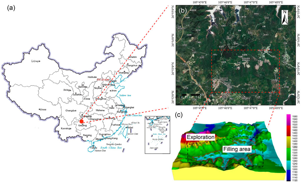
FIGURE 1. Location of the study area.
Geological overview
Lithology
The strata in the study area are mainly composed of shallow water carbonates. The sediment strata are thicker and have abundant biological fossils, such as bivalves and planktonic ammonite. The lithology can be classified as Upper Triassic Xujiahe formation (T3x), which consists of sandstone and shale, and is mainly composed of cross-bedding and oblique bedding, and Middle Triassic Falang (T2f) and Guanling (T2g) formations, which are dominantly composed of argillaceous limestone, siliceous limestone, sandy shale, and calcareous siltstone and dolomite. The geological map is shown in Figure 2.
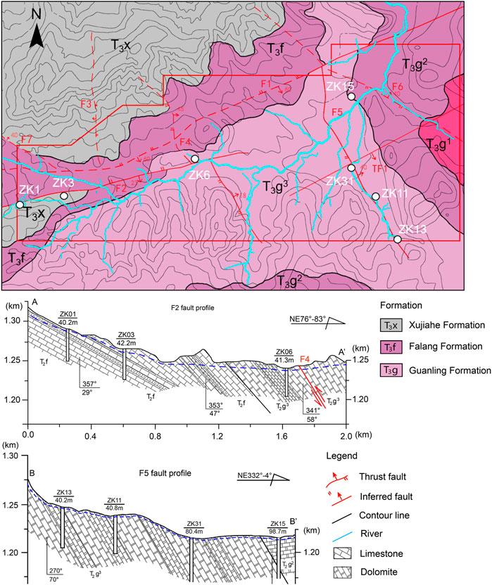
FIGURE 2. Regional lithology and geological structure of the study area.
Tectonic characteristics
The study area is in the Central Guizhou Uplift, which is an EW uplift of Ordovician and Silurian distributed in Zunyi, Guizhou province. There are seven faults in the study area (Figure 2).
Hydrological setting
Surface water
The site is a low-middle mountain erosion, denudation and dissolution landform. The Yichong river flows through the whole site and then flows into the Liugui river in the Hongjiadu Power Station reservoir. There are several mountain streams in the upper reaches of the Yichong River, and the catchment area of the whole field is about 12.5 km2. The upper reach of the Yichong River is about 2 m wide, while the widest part of the lower reaches is 8m, and the maximum cutting depth is 3 m. The riverbed elevation in the study area is 1247 m and 1207 m in the upper and lower reaches, respectively. The water level varies greatly under the influence of atmospheric rainfall, with a general range of 0–1.5 m and a maximum of 3.0 m. The annual average discharge is 0.9 m3/s, and, in general, surface water drainage conditions are good.
Groundwater
The groundwater in the area is of three types: quaternary pore water, clastic rock fissure water and carbonate karst fissure water. The quaternary pore water is mainly supplied by atmospheric precipitation, and its buried depth is controlled by the topography, with maximum and minimum buried depths of 10 m and 1m, respectively. The fracture water mainly occurs in the sandstone fissures and is mainly supplied by atmospheric precipitation and upper quaternary pore water, with a flow rate of 0.5–22 m3/d. The karst fissure water is mainly found in the limestone and dolomitic limestone areas. Especially in the middle section of T2g, grey karst crevasse is relatively developed, there are local large karst caves, and underground rivers with large water volumes have formed, such as Dalongjing river with a flow of 500–3000 m3/d. Rainfall can be up to 2×10⁴ m3/d.
The main aquifers in the site are distributed in limestone, dolomitic limestone, calcinous dolomite, and argillaceous limestone of the Middle Triassic Guanling Formation (T2g), and calcinous dolomite of the Lower Triassic Yongningzhen Formation (T1yn). The dip angle of rock strata is generally low (20°–45°), and the adjacent water-bearing rock groups form independent recharge, runoff and drainage systems, mainly in the form of karst fissure water and karst pipe water, which have poor uniformity and a degree of zonation. In the field test area, two groups of faults (NE trending F1 and NW trending F2, F1 and F4 are dislocated by F2) have developed compression-torsional dense fracture zones on both sides, creating conditions for groundwater migration in the hard rock of limestone and dolomite, so that the fault fracture zone is highly water-rich and highly permeable. In the soft rocks of marl and mudstone, the fault fracture zone is mylonized and has strong water isolation.
Materials and methods
Grouting materials
Cement and cement-based materials are commonly used in the anti-seepage grouting of dam sites and other reservoir structures. Cement pastes are suitable for many geological conditions as its rheology can be adjusted from Newtonian fluid to Bingham fluid simply by changing the water/cement (w/c) ratio. The rheology of base-cement slurry can also be transformed by using different additives, such as accelerator, fluid-loss additives, or extender. In this study, cement-clay (bentonite) slurry and time-dependent viscosity grouting material have been used for anti-seepage grouting in the test area rock mass. Using bentonite to replace cement can adjust the slurry rheology, improve stability, and reduce the permeability, which can reduce the dispersion of slurry under water and increase the filling rate of fracture (Azadi et al., 2017; Benyounes and Benmounah, 2014; Mesboua et al., 2018). On the other hand, Bentonite as a clay mineral can effectively adsorb pollution substances in sewage such as heavy metal ions and organic (Tiller et al., 1984; Khan and Khan, 1995). The addition of bentonite can effectively modify the adsorption characteristics of cement grout to pollutants and improve the durability of anti-seepage body (Calvanese et al., 2002; Cioffi et al., 2001). The time-dependent viscosity grouting material is composed of cement and a variety of admixtures, which has the characteristics of large initial fluidity, fast viscosity change and controllable setting time. The rheology, pumping time, setting time and strength can be adjusted by changing the dosage of admixtures. The slurry with high viscosity and short setting time is suitable for steep-wide cracks and dynamic water environment, and on the contrary is suitable for long and narrow fractures (Zhang et al., 2017).
Cement
The cement used in this study is P.O 42.5R Portland cement (LAFARGE GROUP). The cement was sieved through an 80 μm square-hole sieve so that large particles do not exceed 2.4%, and its properties of setting time and strength meet the standard requirements of common Portland cement (GB175–2007). The main chemical constituents of the cement are listed in Table 1.
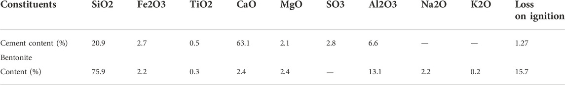
TABLE 1. The chemical constituents of the Portland cement and bentonite.
Clay
The clay used in the test was sodium bentonite mined in Weifang, Shandong province, China. The average particle size of the bentonite was 44μm, and the main chemical component was montmorillonite, as shown in Table 1.
Additives
Superplasticizer: To improve the pumpability and fluidity of the cement-clay slurry with a low w/c ratio, a polycarboxylate plasticizer (XJY-2) was used as an additive in this test.
Time-dependent viscosity grouting material: includes modified fiber (1#), calcium-silicon early strength agent (2#) and acylamide derivatives (3#). The modified fiber (1#) consists mainly of a mixture of organic fibers, while the calcium-silicon early strength agent (2#) consists mainly of inorganic salts, which can provide an alkaline environment for the cement paste and stimulate the hydration of the cement. The setting time can be adjusted by control of the acylamide derivatives (3#) content (Zhang et al., 2017). This grouting material has high initial fluidity, good groutability, and a short setting time. Its rheological and mechanical properties can be adjusted by changing the w/c ratio and the dosage of each additive.
The shattered fault zone anti-seepage grouting needs both to satisfy the requirement of filling ratio and also need to prevent the infinite diffusion of the grouting material. Therefore, the grouting material should have good flowability and suitable pumpable and setting times, and the grouting solidified body should have high strength and low permeability. Based on previous studies, the cement-clay slurry and time-dependent viscosity slurry are used as the grouting materials to compare their suitability for fault fracture zones with flowing water. The composition of grouting materials is shown in Table 2.
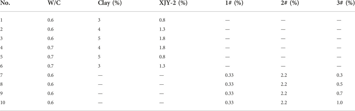
TABLE 2. Composition of the grouts.
Grouting method
Grouting hole arrangement
Two compression-torsion fault zones were selected for the grouting test (Figure 3A). Test area No.1 is located at the intersection of the F2 and F4 faults, 5 m from the Yichong River. The test area is 3.3–5.5 m of weathered limestone with a broken rock mass structure. Below 5.5 m, there is middle weathered limestone with fractures that are fragmentary to massive and filled with sand. A total of five grouting holes were arranged in a triangle with a spacing of 3 m and a row spacing of 3.4 m. The three holes in sequence one are G1, G3 and G5, and the two holes in sequence two are G2 and G4, as shown in Figure 3C. Test area No.2 is located on the upper section of the F5 fault and 50 m away from Sunjiazhai River (Figure 3B). The test area below 2.0 m is middle weathered limestone with fractures, which are fragmentary to massive and filled with sand. A total of five grouting holes were arranged in a triangle with a spacing of 2 m and a row spacing of 2.4 m, this was used for grouting with cement-clay slurry. The three holes in sequence one are G1, G3, and G5, and two holes in sequence two are G2 and G4 (Figure 3D). The I1 and I2 are the inspection holes.
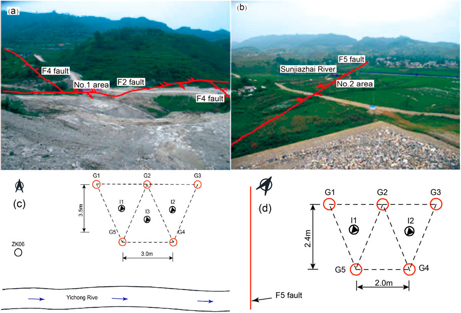
FIGURE 3. The location of the two test areas and grouting hole arrangement in (A) No. 1 test area, (B) No. 2 test area, (C) arrangement in No. 1 test area, and (D) arrangement in No. 2 test area.
Grouting process
In this paper, a new grouting technique consisting of closed local circulating grouting from top to bottom is proposed for use with formations with a loose and broken structure. A schematic diagram of the new grouting process is shown in Figure 4. A water pressure plug is used to separate the grouting section from the non-grouting section. Before grouting, the borehole should be cleaned, and the water should be pressed into borehole from the top of water pressure plug, and then returned from the return pipe. When the returned water is clear without sediment, the hole washing operation can be terminated. During grouting, the slurry is sent to the bottom of the grouting section from the injection pipe and then returned to the return pipe. Through control of the returned volume, the flow rate of grout and grouting can be controlled. Thus, local circulation grouting in the hole under different pressure can be realized. The grouting pressure of the first and second sections is 0.1–0.2 MPa and 0.4–0.8 MPa, respectively. When the grouting pressure of first and second section exceeds 0.3 MPa and 1.0 MPa or the injection rate is less than 1L/min, the grouting can be finished by continuing for a further 15–30 min. When the first grouting section is completed, the first section of the next borehole is constructed. After the first hole section is solidified for 3 days, the drilling and grouting of the next hole section are carried out.
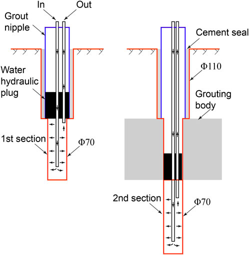
FIGURE 4. The grouting process and method.
Verification method
The water pressure test, also known as the Lugeon test, is the most common approach to detecting rock cracks and permeability in geotechnical engineering (Azimian and Ajalloeian, 2015). The permeability parameters of a curtain structure and test section are determined by this method, providing basic data for evaluating the hydraulic characteristics of a rock mass controlled by discontinuities, water absorption capacity, compactness, and effectiveness of grouting, and also explaining some geomechanical behaviors. In this study, water pressure tests were conducted before and after grouting using a five-step water pressure loading and unloading (Foyo et al., 2005; Lisa et al., 2013) process that generated five sets of water pressure (P) and water discharge (Q) values, one for each of the five steps that are presented as P–Q diagrams for each interval. The final permeability value can be determined from the maximum stress stage (Stage 3).
The calculation of the permeability of the test section from the water pressure tests is shown in Eq. 1:
where q is the permeability of the test section, Lu. Q is the water discharge values, L/min. P is the effective pressure acting on the test section, MPa. L is the length of the test section, m.
To judge the quality change of rock mass before and after grouting, the secondary permeability index (SPI) were used. The SPI is calculated as shown in Eq. 2:
where SPI is the secondary permeability index, l/s per m2 of the borehole test surface. C is a constant depending upon viscosity for an assumed temperature of rock at 10°C, 1.49×10⁻¹⁰. le is the test section length, m t is the test time, s. H is the total pressure expressed as a water column, m.
Results and discussion
Properties of the grouting materials
The rheological and setting properties of the grouts are shown in Table 3, and the apparent viscosity and fluidity are shown in Figure 5. The fluidity of the cement-clay slurry decreases slowly with time and increases with increasing w/c and decreasing clay content. Compared with the cement-clay slurry, the time-dependent viscosity slurry has high initial fluidity under the same w/c ratio, which can be maintained for some time and then rapidly decreases into pumpable time. The fluidity can be controlled by the amount of the three# admixture. As Figure 5C shows, under the condition of similar initial fluidity, the apparent viscosity of time-dependent viscosity slurry increases approximately exponentially with time, while that of the cement-clay slurry remains almost constant. The grouting diffusion radius can be affected directly by grout viscosity and pressure. High fluidity increases the grouting diffusion distance but makes it difficult to increase the grouting pressure to the design value. In addition, groundwater will cause erosion and dilution of the grout, and the lower the viscosity after perfusion, the more serious the erosion. Therefore, in the grouting of water-rich broken rock mass, the grout should ideally have high initial fluidity, a controllable pumping time and a shorter initial setting time.
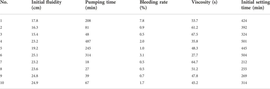
TABLE 3. The properties of grouts with different composition.
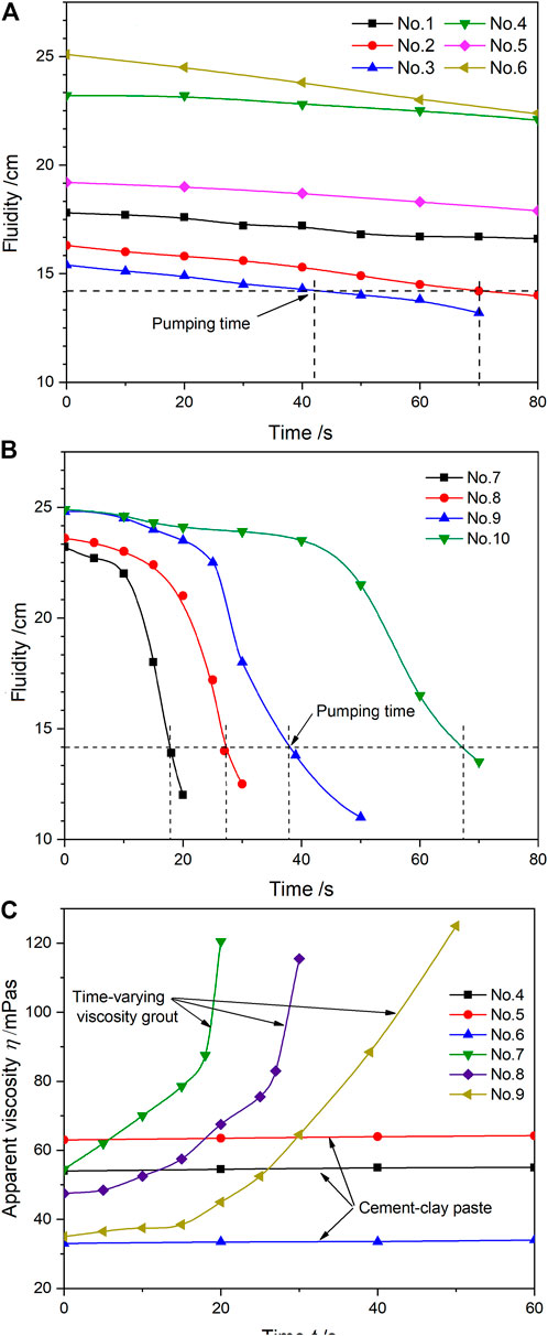
FIGURE 5. The variation of fluidity and viscosity with time for the cement-clay slurry and the time-dependent viscosity slurry.
The anti-seepage capacity is affected by the compressive strength and permeability of the stone body of grout. The unconfined compressive strength of the two grouts is shown in Table 4. The pre and post compressive strength of time-dependent viscosity slurry are both higher than those of the cement-clay slurry. The 28 days strength is greater than 20 MPa, which meets the requirements of curtain grouting. The strength of the cement-clay slurry increases with time and decreases with increasing w/c ratio and clay content. The strength of time-dependent viscosity slurry decreases with the increase of admixture.
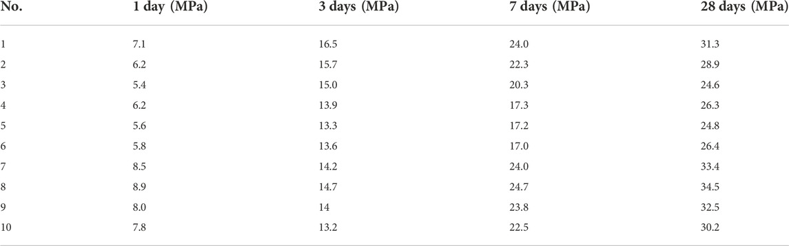
TABLE 4. The strength properties of the grout.
Figure 6 shows the evolution of permeability and contaminant retardancy with time. The permeability coefficients of the grouts increase with time and are affected by their composition. The permeability coefficient of the cement-clay slurry decreases with increasing clay content, while that of the time-dependent viscosity slurry is not affected by the amount of admixture. The arrest rates of Hg, As, Pb and Cd were more than 99%. The heavy metal arrest rate of cement clay slurry is affected by the clay content. When the clay content is 4%, the arrest rate is the highest.
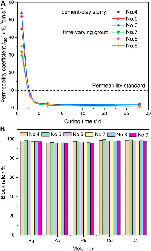
FIGURE 6. Relationship between permeability coefficient and curing time for the two slurries, and blocking rate for heavy metal ions.
The difference of rheological-hardening characteristics of the two kinds of grout is mainly caused by cement hydration. Due to the high water absorption of bentonite, the free water in the system decreases with the increase of dosage, and a large amount of free water is closed in the network space composed of cement and clay particles, which leads to the decrease of slurry fluidity, the increase of viscosity and the improvement of stability. However, the mutual adsorption of bentonite and cement reduces the hydration rate of cement. So the setting time of the slurry is extended. On the contrary, the time-depending viscosity additives increase the hydration rate and products by adjusting the early hydration of cement to change the viscosity and setting time.
Analysis of grout take
Figure 7 and Table 5 show the total and unit grout take, respectively, of formations with different degrees of weathering in the two test areas. Figure 7A shows that the grout takes of the strongly weathered limestone is between 750 and 1640 L, while that of the medium weathered formation is between 460 and 687 L. Figure 7B shows that the grouting volume of the upper middle weathered formation is between 520 L and 750 L, while that of the lower formation is between 980 L and 3150 L. The unit grout takes of strongly weathered formation with time-varying grout is the same as that of the two test areas with cement-clay grout, but it is 31% in the medium weathered formation.
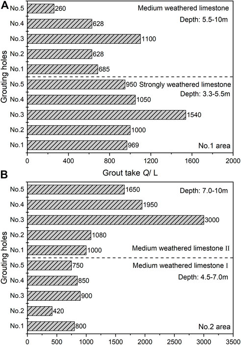
FIGURE 7. Grout take and depth relationship for the No. 1 and No. 2 test areas.
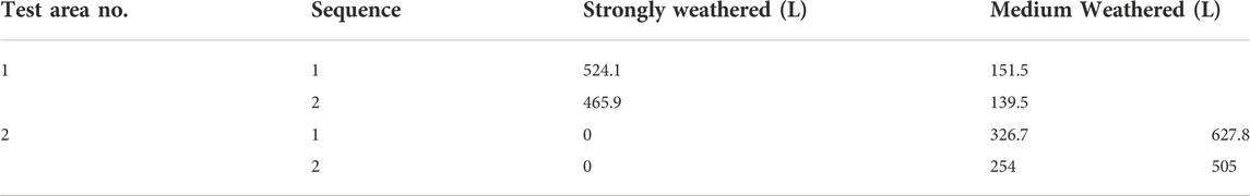
TABLE 5. The average grout take of 1-m depth in the different weathered formations.
This result indicates that the grout take is controlled both by formation conditions and grout rheology. The two kinds of grout have the same initial rheological parameters, which ensures the diffusion of grout through the formation. With the extension of grouting time, the viscosity of time-dependent slurry suddenly increases, which increases the shear stress required for its flow in the formation pores, slowing down the diffusion speed and reducing the grouting take. While the yield stress of the cement-clay slurry remains constant, a large amount of slurry is needed to achieve mechanical equilibrium in the grouting process. Hence, the grouting quantity difference under the same formation conditions.
Analysis of permeability coefficient before and after grouting
The P-Q diagram types (hydromechanical behavior) of the rock mass before and after grouting were identified using the five-stage water pressure tests (WPTs) and statistically analyzed. Typical P-Q diagrams are shown in Figure 8 and Figure 9 in the form of a straight line, which includes both the strongly and medium weathered formation before and after grouting in the two test areas. Based on the complete hydromechanical behavior model for the fault, the following points are obtained.
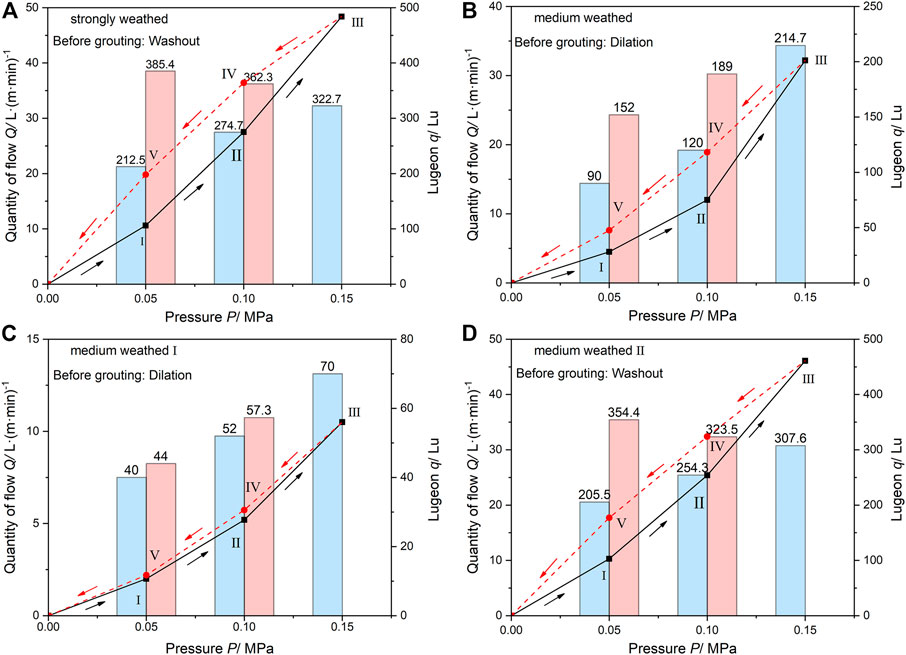
FIGURE 8. Formation permeability before grouting (A) strongly weathered formation of No. 1 test area, (B) medium weathered formation of No. 1 test area, (C,D) the upper and lower weathered formations of No. 2 test area.
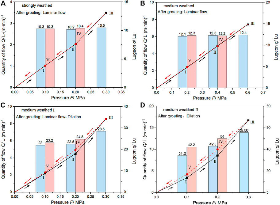
FIGURE 9. Formation permeability after grouting (A) strongly weathered formation of No. 1 test area, (B) medium weathered formation of No.1 test area, (C,D) the upper and lower weathered formation of No. 2 test area.
With respect to the behavior of the two test areas, the strongly weathered formation is washout, while the medium weathered formation can be divided into dilation and washout (Figure 8). The results of the WPTs of No.1 test area indicate washout to be the dominant behavior in depths of 3.3 m–5.5 m. The Lugeon values of the five pressure stages are 212.5 Lu, 274.7 Lu, 322.7 Lu, 362.3 Lu, and 395.4 Lu, respectively (Figure 8A). In the process of the water pressure, the water erodes and carries the filling materials between the pores and cracks of formation, and causes plastic deformation of the rock mass. Therefore, the permeability increases significantly during the low pressure stages 4 and 5. In depths of 5.5 m–10 m, the dominant behavior is dilation, the Lugeon values of stages 4 and 5 are bigger than stages 1 and 2 (Figure 8B). This result indicate that the joints experience elastic widening or slight erosion under the effect of pressure. In the No.2 test area, the hydromechanical behaviors are dilation from 4.5 m to 7 m and washout from 7 m to 10.2 m, with permeabilities of 58.1 Lu and 307.6 Lu, respectively (Figure 8C,D). The reason for this phenomenon may be that the deep rock mass is more affected by the fault structure than the shallow. The fragmentation degree of deep rock mass is greater than that of shallow rock mass, and the fissure filling material is obviously eroded by groundwater. Overall, the degree of rock fragmentation in No. One test area is greater than that in No. Two test area.
The WPTs results for the two inspection boreholes in No.1 test area indicate that the hydromechanical behavior changes from washout and dilation to laminar flow after time-dependent viscosity slurry grouting (Figure 9A,B). The path of water flow changes is consistent during the pressure rise and fall phases, which suggest that the water channel is no longer deformed under pressure. The permeability coefficient of the two grouting sections decreases by 90% and 95%, respectively, and is roughly the same (10 Lu). Therefore, it can be concluded that the quality of rock mass in time-dependent viscosity slurry grouting area tend to be consistent, and the cracks normally tend to closed and a small section are not completely filled. In No.2 test area, the hydromechanical behavior of first grouting section changes from dilation to laminar, but the pressure rise and fall curves still exist gap (Figure 9C), which indicates that the grouting consolidation body still has some deformation under the action of pressure. The second section changes from washout to dilation (Figure 9D), which shows that the joint structure is partially or mostly still open. The permeability of the two grouting sections decreases by 50.9% and 81.9%, but there is still a big difference. It indicates that the grouting quality of cement-clay slurry is quite different.
The permeability level is calculated by SPI, and this is used to classify the rock mass of the test areas. The SPI classes are given in Table 6. The SPI values for the formation before grouting show that 100% of the tested intervals fall within the D (>80 Lu, very poor), this means the formation needs to be grouted. After grouting, the SPI values of No.1 test area fall to 1.22×10⁻¹³–9.81×10⁻¹⁴, which can be classified as B-C (Good-fair to Poor). Similarly, the SPI values of the No.2 test area reduce to 2.37×10⁻¹³–9.78×10⁻¹³, which can be classified as C to D (Poor to Very Poor).
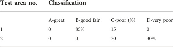
TABLE 6. Rock mass classification in the two areas after grouting.
Based on the grout take and permeability analysis, the consumption of time-dependent viscosity slurry is 27.4% less than cement-clay slurry under the same engineering and hydrogeological conditions and can significantly reduce the degree of fracture (or pore) in the fault zone, reduce the permeability, and improve the quality grade of the rock mass. The different arises due to the following factors. The good initial fluidity and low viscosity of the time-dependent viscosity slurry ensure a good diffusion distance in the formation. With the extension of grouting time, the rheology of the front grout changes abruptly from fluid to plastic paste, thus, blocking the flow of the subsequent grout, thereby increasing of grouting pressure and the filling rate and compactness of the pores by the slurry are significantly increased under the action of this additional pressure. In contrast, the fluidity of the cement-clay slurry changes slowly, resulting in its continuous diffusion to the periphery under the action of grouting pressure, making it difficult for grout to compact and fill the pores. In addition, the cement-clay slurry with high dispersion is easily eroded by groundwater, while the high viscosity and quick setting of time-dependent viscosity slurry can effectively resist the dispersion of groundwater and ensure the filling rate of pores. The cement-clay slurry has poor stability, and its water absorption rate is four times that of time-dependent slurry. During the process of setting, the volume contraction causes the filled cracks to open again, which is also a reason for the poor quality of cement-clay grouting. Therefore, it can be concluded that the rheology-setting characteristics of slurry and the grouting pressure have great influence on the seepage prevention of fault fracture zone.
Conclusion
Curtain grouting is an important element of seepage control design in landfill, chemical plant and water conservation, and hydropower projects. Based on the experimental analysis of the rheology-setting properties for a time-dependent viscosity slurry and a cement-clay slurry, this study focuses on anti-seepage treatment in a water-bearing fault fracture zone, analyzing the permeability before and after grouting by different approaches. From the results, the following conclusions can be drawn:
1) Under the condition of the same initial fluidity, the pumping time of time-dependent viscosity slurry is 3.7%–21.3% that of the cement-clay slurry and can be adjusted within 18–67 min. The water bleeding of the cement-clay slurry is 1.8–4 times that of the time-dependent viscosity slurry.
2) The mechanical properties of time-dependent slurry is great than cement-clay, and the 28 days unconfined compressive strength is 30.2–34.5 MPa and 24.6–31.3 MPa, respectively. The three# additive content of 0.5% is the optimum dosage to produce a stable grout with highest strength. A bentonite content of 3% and 0.6 w/c ratio is the optimum dosage to obtain maximum strength.
3) The permeability coefficients of the two slurry stone bodies are of the same level (<10−7 cm/s), and the blocking rates of Hg, As, Pb and Cd heavy metal ions reach more than 99%.
4) Under the same grouting depth, the consumption of cement-clay slurry (12300 L) is 1.4 times that of time-dependent viscosity slurry (8931 L), while its grouting pressure (0.3–0.4 MPa) is 50% lower.
5) The permeability coefficient of the formation with time-dependent viscosity slurry decrease from 214.7 to 322.7 Lu to 10.3–12.3 Lu, reduced by 95.2%–96.2%. The hydromechanical behavior is changed to laminar flow, and the rock mass quality is improved from grade D to grade B-C, basically realizing the sealing of fractures.
6) The permeability of the formation with cement-clay slurry decrease from 58.1 Lu and 307.6 Lu to 28.5 Lu and 55.6 Lu, only decreased by 50.9% and 81.9%, and the mass of rock mass only increased to C-D level, with most fractures in the open state with the cement-clay slurry.
Results of the grouting test indicate that it is possible to use the method of closed local circulating grouting from top to bottom to reduce the permeability of water-bearing fault zone. In terms of grouting materials, both the grout takes and grouting quality, time-dependent viscosity slurry is better than cement-clay slurry.
Data availability statement
The original contributions presented in the study are included in the article/supplementary material, further inquiries can be directed to the corresponding author.
Author contributions
All authors listed have made a substantial, direct, and intellectual contribution to the work and approved it for publication.
Funding
The authors are grateful for the financial support of the Key Research and Development Programme of Sichuan Province (2021YFQ0066); State Key Laboratory of Geohazard Prevention and Geoenvironment Protection (China) Open Fund (SKLGP 2022K021).
Conflict of interest
The authors declare that the research was conducted in the absence of any commercial or financial relationships that could be construed as a potential conflict of interest.
Publisher’s note
All claims expressed in this article are solely those of the authors and do not necessarily represent those of their affiliated organizations, or those of the publisher, the editors and the reviewers. Any product that may be evaluated in this article, or claim that may be made by its manufacturer, is not guaranteed or endorsed by the publisher.
References
Adamovic, D., Ishiyama, D., Kawaraya, H., Ogawa, Y., and Stevanovic, Z. (2022). Geochemical characteristics and estimation of groundwater pollution in catchment areas of Timok and Pek Rivers, Eastern Serbia: Determination of early-stage groundwater pollution in mining areas. Groundw. Sustain. Dev. 16, 100719. doi:10.1016/j.gsd.2021.100719
Azadi, M. R., Taghichian, A., and Taheri, A. (2017). Optimization of cement-based grouts using chemical additives. J. Rock Mech. Geotechnical Eng. 9, 623–637. doi:10.1016/j.jrmge.2016.11.013
Azimian, A., and Ajalloeian, R. (2015). Permeability and groutability appraisal of the Nargesi dam site in Iran based on the secondary permeability index, joint hydraulic aperture and Lugeon tests. Bull. Eng. Geol. Environ. 74, 845–859. doi:10.1007/s10064-014-0675-8
Benyounes, K., and Benmounah, A. (2014). Effect of bentonite on the rheological behavior of cement grout in presence of superplasticizer. Int. J. Civ. Archit. Struct. Constr. Eng. 8, 1095–1098.
Calvanese, G., Cioffi, R., and Santoro, L. (2002). Cement stabilization of tannery sludge using quaternary ammonium salt exchanged bentonite as pre-solidification adsorbent. Environ. Technol. 23, 1051–1062. doi:10.1080/09593332308618351
Carter, T. G., Dershowitz, W., Shuttle, D., and Jefferies, M. (2012). Improved methods of design for grouting fractured rock. Grouting Deep Mix. 228, 1472–1483 doi:10.1061/9780784412350.0123
Cioffi, R., Costanzo, S., Maffucci, L., and Santoro, L. (2001). Adsorption of the organic fraction of a tannery sludge by means of organophilic bentonite. Environ. Technol. 22, 83–89. doi:10.1080/09593332208618309
Eklund, D., and Stille, H. (2008). Penetrability due to filtration tendency of cement-based grouts. Tunn. Undergr. Space Technol. 23, 389–398. doi:10.1016/j.tust.2007.06.011
Esteller, M. V., Domínguez-Mariani, E., Garrido, S. E., and Avilés, M. (2015). Groundwater pollution by arsenic and other toxic elements in an abandoned silver mine, Mexico. Environ. Earth Sci. 74, 2893–2906. doi:10.1007/s12665-015-4315-9
Ewert, F.-K. (1998). Permeability, groutability and grouting of rocks related to dam sites Part 4. Dam Eng. 8, 271–326.
Foster, M., Fell, R., and Spannagle, M. (2000). The statistics of embankment dam failures and accidents. Can. Geotech. J. 37, 1000–1024. doi:10.1139/t00-030
Foyo, A., Sanchez, M. A., and Tomillo, C. (2005). A proposal for a secondary permeability index obtained from water pressure tests in dam foundations. Eng. Geol. 77, 69–82. doi:10.1016/j.enggeo.2004.08.007
Fransson, Å. (2001). Characterisation of a fractured rock mass for a grouting field test. Tunn. Undergr. Space Technol. 16, 331–339. doi:10.1016/s0886-7798(01)00060-8
Gworek, B., Dmuchowski, W., Koda, E., Marecka, M., Baczewska, A. H., Brągoszewska, P., et al. (2016). Impact of the municipal solid waste Łubna Landfill on environmental pollution by heavy metals. Water 8, 470. doi:10.3390/w8100470
Huang, Y., Tang, Y., Zhou, Z., and Yu, Z. (2014). Experimental investigation of contaminant migration in filled fracture. Environ. Earth Sci. 71, 1205–1211. doi:10.1007/s12665-013-2524-7
Hussein, M., Yoneda, K., Mohd-Zaki, Z., Amir, A., and Othman, N. (2021). Heavy metals in leachate, impacted soils and natural soils of different landfills in Malaysia: An alarming threat. Chemosphere 267, 128874. doi:10.1016/j.chemosphere.2020.128874
Jiang, H., and Qiu, X. (2021). Performance assessment of a newly developed and highly stable grouting material for a completely weathered granite dam foundation. Constr. Build. Mater. 299, 123956. doi:10.1016/j.conbuildmat.2021.123956
Khan, S. A., and Khan, M. A. (1995). Adsorption of chromium (III), chromium (VI) and silver (I) on bentonite. Waste Manag. 15, 271–282. doi:10.1016/0956-053x(95)00025-u
Lee, H. B., Oh, T.-M., Park, E.-S., Lee, J.-W., and Kim, H.-M. (2017). Factors affecting waterproof efficiency of grouting in single rock fracture. Geomech. Eng. 12, 771–783. doi:10.12989/gae.2017.12.5.771
Lisa, H., Gunnar, G., Åsa, F., and Tommy, N. (2013). A statistical grouting decision method based on water pressure tests for the tunnel construction stage–A case study. Tunn. Undergr. Space Technol. 33, 54–62. doi:10.1016/j.tust.2012.08.004
Liu, Y., and Chen, B. (2019). Research on the preparation and properties of a novel grouting material based on magnesium phosphate cement. Constr. Build. Mater. 214, 516–526. doi:10.1016/j.conbuildmat.2019.04.158
Mesboua, N., Benyounes, K., and Benmounah, A. (2018). Study of the impact of bentonite on the physico-mechanical and flow properties of cement grout. Cogent Eng. 5, 1446252. doi:10.1080/23311916.2018.1446252
Mortazavi, A., and Maadikhah, A. (2016). An investigation of the effects of important grouting and rock parameters on the grouting process. Geomechanics Geoengin. 11, 219–235. doi:10.1080/17486025.2016.1145255
Raghavendra, N. S., and Deka, P. C. (2015). Sustainable development and management of groundwater resources in mining affected areas: A review. Procedia Earth Planet. Sci. 11, 598–604. doi:10.1016/j.proeps.2015.06.061
Stare, D. P., Dreese, T. L., and Bruce, D. A. (2013). Contemporary drilling and grouting methods. Boca Raton, FL: CRC Press.
Stille, B., Stille, H., Gustafson, G., and Kobayashi, S. (2009). Experience with the real time grouting control method. Geomech. Tunnelbau 2, 447–459. doi:10.1002/geot.200900036
Stille, H., Gustafson, G., and Hassler, L. (2012). Application of new theories and technology for grouting of dams and foundations on rock. Geotech. Geol. Eng. (Dordr). 30, 603–624. doi:10.1007/s10706-012-9512-7
Tiller, K. G., Gerth, J., and Brümmer, G. (1984). The relative affinities of Cd, Ni and Zn for different soil clay fractions and goethite. Geoderma 34, 17–35. doi:10.1016/0016-7061(84)90003-x
Xaypanya, P., Takemura, J., Chiemchaisri, C., Seingheng, H., and Tanchuling, M. A. N. (2018). Characterization of landfill leachates and sediments in major cities of indochina peninsular countries—Heavy metal partitioning in municipal solid waste leachate. Environments 5, 65. doi:10.3390/environments5060065
Xu, S. F., and Yang, Y. (2006). Use of impermeable materials for refuse landfills in Japan. Environ. Eng. 24, 68–70.
Yao, R., Yan, Y., Wei, C., Luo, M., Xiao, Y., and Zhang, Y. (2022). Hydrochemical characteristics and groundwater quality assessment using an integrated approach of the pca, som, and fuzzy c-means clustering: A case study in the northern sichuan basin. Front. Environ. Sci. 648. doi:10.3389/fenvs.2022.907872
Zhang, C., Fu, J., Yang, J., Ou, X., Ye, X., and Zhang, Y. (2018). Formulation and performance of grouting materials for underwater shield tunnel construction in karst ground. Constr. Build. Mater. 187, 327–338. doi:10.1016/j.conbuildmat.2018.07.054
Zhang, J., Pei, X., Wang, W., and He, Z. (2017). Hydration process and rheological properties of cementitious grouting material. Constr. Build. Mater. 139, 221–231. doi:10.1016/j.conbuildmat.2017.01.111
Zhang, Y.-H., Yao, R.-W., Wang, Y., Duo, J., and Cao, H.-W. (2022). Zircon U–Pb and sericite Ar–Ar geochronology, geochemistry and S–Pb–Hf isotopes of the Zebuxia Pb–Zn deposit, Tibet, southwestern China. Ore Geol. Rev. 148, 104999. doi:10.1016/j.oregeorev.2022.104999
Zhang, Y., Dai, Y., Wang, Y., Huang, X., Xiao, Y., and Pei, Q. (2021a). Hydrochemistry, quality and potential health risk appraisal of nitrate enriched groundwater in the Nanchong area, southwestern China. Sci. Total Environ. 784, 147186. doi:10.1016/j.scitotenv.2021.147186
Keywords: permeation grouting, cement-clay slurry, time-dependent viscosity, water pressure, penetrability
Citation: Zhang J, Pei X, He Z, Pei Z and Zheng G (2023) Comparison of time-dependent viscosity slurry and cement-clay slurry for anti-seepage grouting on faults. Front. Earth Sci. 10:1037791. doi: 10.3389/feart.2022.1037791
Received: 06 September 2022; Accepted: 26 October 2022;
Published: 11 January 2023.
Edited by:
Chengyi Pu, Central University of Finance and Economics, ChinaReviewed by:
Eyübhan AVCI, Bursa Technical University, TurkeyYoujun Ning, Southwest Petroleum University, China
Zuochun Li, China University of Geosciences, China
Copyright © 2023 Zhang, Pei, He, Pei and Zheng. This is an open-access article distributed under the terms of the Creative Commons Attribution License (CC BY). The use, distribution or reproduction in other forums is permitted, provided the original author(s) and the copyright owner(s) are credited and that the original publication in this journal is cited, in accordance with accepted academic practice. No use, distribution or reproduction is permitted which does not comply with these terms.
*Correspondence: Xiangjun Pei, cGVpeGowMTE5QHRvbS5jb20=